The GE Multilin 845 is a widely used numerical relay designed for the protection of two-winding and three-winding power transformers. It is manufactured by GE Grid Solutions and is deployed across utility substations, industrial plants, and generation facilities around the world. The relay offers multiple protection functions under a single platform, including transformer differential protection (ANSI 87T), overcurrent protection (ANSI 50/51), restricted earth fault protection (ANSI 87N), overexcitation protection (ANSI 24), and thermal overload protection (ANSI 49). Proper settings calculation for the GE 845 relay is fundamental to achieving reliable transformer protection and avoiding nuisance tripping during external faults, inrush conditions, and overexcitation events.
In this technical guide, we will discuss everything you need to know about GE 845 transformer protection relay settings calculation, including its protection functions, ANSI codes, tap setting calculations, slope characteristic, overcurrent settings, restricted earth fault configuration, testing methods, and relevant industry standards. Practical examples are included throughout to help you apply these concepts in real-world scenarios confidently.
1. Overview of the GE Multilin 845 Relay
The GE 845 relay belongs to the GE Multilin family of digital protection relays. It is purpose-built for transformer applications and supports two-winding and three-winding transformer configurations. The relay uses a microprocessor-based platform that processes current and voltage signals in real time. It performs internal compensation for CT ratio mismatch, vector group differences, and zero-sequence current elimination. This means the relay can handle most transformer connection types without external interposing CTs.
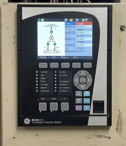
The relay communicates through standard protocols such as Modbus, DNP3, and IEC 61850. It also features built-in disturbance recording, event logging, and self-monitoring capabilities. Engineers can configure the relay using the front panel interface or the GE EnerVista software tool installed on a PC. The EnerVista software provides a user-friendly environment for entering settings, reviewing metering data, and downloading fault records.
One of the major advantages of the GE 845 is its ability to perform automatic vector group compensation and ratio correction internally. This reduces hardware complexity and minimizes wiring errors. However, the engineer must still input the correct transformer data and CT parameters so the relay can calculate these compensations accurately.
2. ANSI Protection Functions Available in the GE 845
The GE 845 relay supports a range of ANSI-standard protection functions. Each function addresses a different type of fault or abnormal operating condition. Below is a list of the most commonly used protection functions in the GE 845 relay:
ANSI 87T – Transformer Percentage Differential Protection: This is the primary protection function. It compares the current entering the transformer on the primary side with the current leaving on the secondary side. Any mismatch beyond a defined threshold indicates an internal fault.
ANSI 87N – Restricted Earth Fault Protection: This function detects ground faults within the transformer winding zone. It uses the residual current from the phase CTs and the neutral CT to identify internal earth faults with high sensitivity.
ANSI 50/51 – Phase Overcurrent Protection: This function provides backup protection against phase-to-phase and three-phase faults. The instantaneous element (50) operates without intentional time delay. The time-overcurrent element (51) operates on an inverse time characteristic.
ANSI 50N/51N – Ground Overcurrent Protection: This provides backup protection for ground faults detected on each winding of the transformer.
ANSI 24 – Overexcitation (Volts/Hz) Protection: This protects the transformer against excessive magnetic flux caused by overvoltage or underfrequency conditions. The relay calculates the V/Hz ratio and trips if it exceeds the defined limit.
ANSI 49 – Thermal Overload Protection: This function uses a thermal model to estimate the winding temperature based on measured load current. It prevents the transformer from operating beyond its thermal limits.
ANSI 46 – Negative Sequence Overcurrent: This detects unbalanced loading or open-phase conditions that can cause excessive heating in the transformer.
3. Transformer Data Required for Settings Calculation
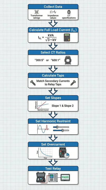
Before entering any settings into the GE 845 relay, you must collect the following data from the transformer nameplate and the system design documents:
- Transformer MVA rating (base MVA)
- Primary winding voltage (kV)
- Secondary winding voltage (kV)
- Tertiary winding voltage (if applicable)
- Vector group or winding connection (e.g., Dyn11, YNd1)
- Impedance (percent Z on transformer base)
- Tap changer range (minimum and maximum tap positions)
- CT ratios on primary side
- CT ratios on secondary side
- CT ratios on neutral (if restricted earth fault is used)
- System fault levels on each side
This information is the starting point for all relay settings calculations. Any error in these values will propagate through every calculated parameter.
4. CT Ratio Selection
Current transformer (CT) selection directly affects the accuracy of the differential protection function. The CT ratios on each side of the transformer must be chosen to match the full-load current of the corresponding winding. Ideally, the CT secondary current at full load should be close to 5A or 1A depending on the CT standard used.
For example, consider a 40 MVA, 132/33 kV transformer with a Dyn11 vector group.
Primary full-load current:
\(I_{primary} = MVA \times \dfrac{1000}{(\sqrt{3} \times kV)}\)
\(I_{primary} = 40 \times \dfrac{1000}{(\sqrt{3} \times 132)}\)
\(I_{primary} = \dfrac{40000}{228.63}\)
\(I_{primary} = 174.95 A\)
A suitable CT ratio for the primary side would be 200/5 A (ratio = 40).
Secondary full-load current:
\(I_{secondary} = 40 \times \dfrac{1000}{(\sqrt{3} \times 33)}\)
\(I_{secondary} = \dfrac{40000}{57.16}\)
\(I_{secondary} = 699.8 A\)
A suitable CT ratio for the secondary side would be 800/5 A (ratio = 160).
The GE 845 relay accepts these CT ratios as direct inputs. The relay then internally calculates the compensation needed to balance the differential currents.
5. Tap Setting Calculation for Differential Protection (ANSI 87T)
The tap setting is one of the most important parameters in transformer differential relay configuration. The tap value represents the expected CT secondary current at the relay terminals under normal full-load conditions. The GE 845 relay uses these tap values to normalize the currents from each winding before performing the differential comparison.
Tap Calculation Formula:
\(\text{Tap} = \dfrac{\text{Transformer Full-Load Current}}{\text{CT Ratio}}\)
Using the same 40 MVA, 132/33 kV example:
Primary Tap:
\(Tap_{primary} = \dfrac{I_{primary}}{CT_{ratio\,primary}}\)
\(Tap_{primary} = \dfrac{174.95}{40}\)
\(Tap_{primary} = 4.37 A\)
Secondary Tap:
\(Tap_{secondary} = \dfrac{I_{secondary}}{CT_{ratio\,secondary}}\)
\(Tap_{secondary} = \dfrac{699.8}{160}\)
\(Tap_{secondary} = 4.37 A\)
In an ideal scenario, both taps should be equal after vector group compensation. If they are not perfectly equal, the relay will still operate correctly as long as the mismatch is within the defined percentage slope setting. The GE 845 relay allows you to enter the taps directly or let the relay auto-calculate them based on the transformer MVA and CT ratios entered in the configuration settings.
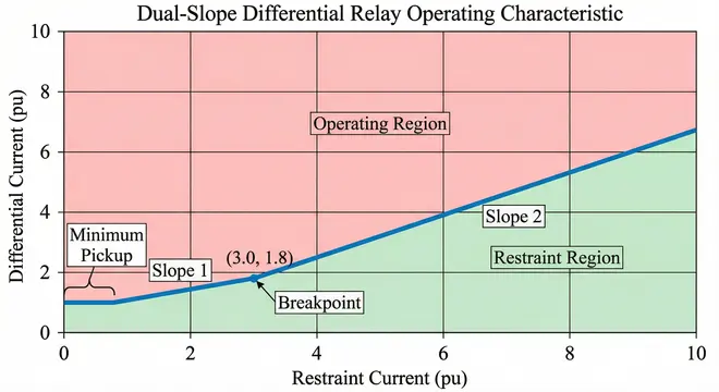
6. Percentage Differential Slope Settings
The differential slope characteristic determines how sensitive or secure the relay is against false operation during external faults and CT saturation. The GE 845 relay uses a dual-slope or multi-slope differential characteristic.
6.1 Slope 1 (Low Current Region)
This slope applies during normal load conditions and low-current through-faults. A common setting is 20% to 30%. This means the relay will tolerate up to 20-30% mismatch between the primary and secondary currents before declaring a fault.
6.2 Slope 2 (High Current Region)
This slope applies during high-current through-faults where CT saturation is more likely. A common setting is 50% to 80%. This higher slope provides greater security against CT errors at high fault currents.
6.3 Breakpoint
The breakpoint is the restraint current level at which the relay transitions from Slope 1 to Slope 2. It is often set around 1.0 to 2.0 times the tap value.
6.4 Minimum Pickup
This is the minimum differential current required to start the relay. It is often set at 0.2 to 0.3 times the tap value (i.e., 20% to 30% of rated current).
For our 40 MVA example, a reasonable starting configuration would be:
- Minimum Pickup: 0.25 pu (25% of tap)
- Slope 1: 25%
- Slope 2: 60%
- Breakpoint: 1.5 pu
These values should be adjusted based on the transformer tap changer range, CT class, and the expected maximum through-fault current.
7. On-Load Tap Changer (OLTC) Compensation
Transformers equipped with on-load tap changers introduce a variable turns ratio. This means the ratio of primary to secondary current changes as the tap position changes. The differential relay must accommodate this variation without falsely operating.
The GE 845 relay handles OLTC compensation by allowing the engineer to enter the tap changer range (e.g., ±10%). The relay then adjusts its internal calculations accordingly. However, the minimum pickup and Slope 1 must be set high enough to cover the full range of mismatch caused by tap position changes.
For a transformer with a ±10% tap range, the maximum ratio error due to tap position is approximately 10%. Therefore, setting the minimum pickup below 10% would risk false tripping at extreme tap positions. A minimum pickup of 20% to 30% provides adequate margin.
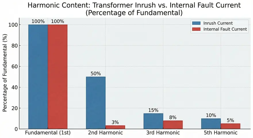
8. Harmonic Restraint and Blocking Settings
Transformer energization produces inrush current that is rich in second harmonic content. Overexcitation conditions produce current with a high third harmonic content. The GE 845 relay uses harmonic analysis to distinguish between genuine internal faults and these non-fault conditions.
8.1 Second Harmonic Restraint (Inrush Blocking)
The relay measures the ratio of second harmonic current to fundamental current in the differential signal. If this ratio exceeds the set threshold, the relay is restrained from tripping. The default setting is usually 15% to 20%. This means if the second harmonic content exceeds 15-20% of the fundamental, the relay assumes it is an inrush condition and blocks the trip.
8.2 Fifth Harmonic Restraint (Overexcitation Blocking)
The relay monitors the fifth harmonic content. If the fifth harmonic ratio exceeds the threshold (commonly set at 25% to 35%), the relay blocks the trip and attributes the differential current to overexcitation.
8.3 Cross-Blocking
The GE 845 relay supports cross-blocking logic. If one phase detects high harmonic content, the relay can block all three phases from tripping. This is helpful during sympathetic inrush conditions where one phase may not show sufficient harmonic content. Cross-blocking is generally recommended for transformer applications and should be enabled.
9. Overcurrent Protection Settings (ANSI 50/51)
The GE 845 relay includes phase and ground overcurrent elements that serve as backup protection. These elements should be coordinated with upstream and downstream protective devices.
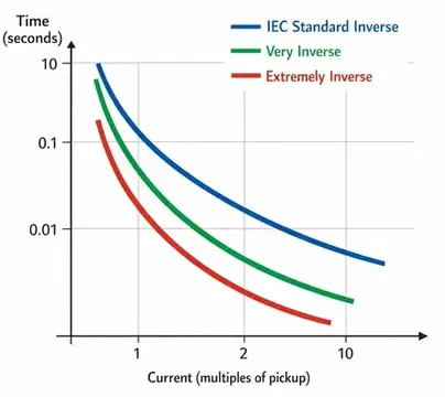
9.1 Time Overcurrent (51) Settings
The pickup value for the time-overcurrent element on the primary side should be set above the maximum expected load current, including overload allowances. A common practice is to set the pickup at 1.25 to 1.5 times the full-load current referred to the CT secondary.
Using our example:
\(\text{51 Pickup} = 1.3 \times \text{Tap}_{primary} = 1.3 \times 4.37 = 5.68 A\)
The time dial should be selected to coordinate with the downstream relay. Standard inverse, very inverse, or extremely inverse curves (per IEC 60255 or IEEE C37.112) can be selected in the relay.
9.2 Instantaneous Overcurrent (50) Settings
The instantaneous element should be set above the maximum through-fault current to avoid tripping for external faults. A setting of 1.25 times the maximum through-fault current (referred to CT secondary) is a common guideline. Alternatively, some engineers set it at 8 to 10 times the full-load current of the winding.
9.3 Ground Overcurrent (51N/50N) Settings
The ground overcurrent pickup depends on the transformer grounding method. For solidly grounded transformers, the ground pickup can be set between 0.2 to 0.5 times the full-load current. For resistance-grounded systems, the pickup should be set based on the maximum ground fault current allowed through the grounding resistor.
10. Restricted Earth Fault Protection Settings (ANSI 87N)
Restricted Earth Fault (REF) protection is applied to the star-connected winding of the transformer. It provides high sensitivity for ground faults near the neutral point of the winding, where the differential protection has reduced sensitivity.
The GE 845 relay implements REF protection using a differential principle. It compares the residual current from the three-phase CTs with the current measured by the neutral CT. If there is a mismatch, a ground fault within the protected zone is indicated.
10.1 REF Pickup Setting
The pickup is set as a percentage of the CT rated current. A common setting is 5% to 20% of the CT rating. For a 5A CT, this translates to 0.25 A to 1.0 A.
10.2 REF Slope Setting
The slope for REF is set to provide stability during external ground faults. A setting of 0% to 20% is often used for low-impedance REF schemes in numerical relays.
In many practical installations, the REF pickup is set at 10% of the CT rating. This provides good sensitivity for turn-to-ground faults near the neutral end of the winding without causing nuisance tripping due to CT errors.
11. Overexcitation Protection Settings (ANSI 24)
Overexcitation occurs when the volts-per-hertz (V/Hz) ratio applied to the transformer exceeds the design limit. This causes excessive magnetic flux in the core, leading to core saturation and overheating.
The GE 845 relay calculates the V/Hz ratio from the measured voltage and frequency inputs. The relay offers two stages of overexcitation protection:
11.1 Stage 1 (Alarm)
This stage is set to provide an early warning. A common setting is 1.05 pu (105% V/Hz) with a definite time delay of 30 to 60 seconds.
11.2 Stage 2 (Trip)
This stage is set to trip the transformer before damage occurs. A common setting is 1.10 to 1.15 pu with an inverse time characteristic or a definite time delay. The inverse time characteristic allows the relay to tolerate brief overexcitation events (such as during load rejection) and trips faster for higher V/Hz ratios.
The transformer manufacturer’s V/Hz capability curve should be used to set the overexcitation relay characteristic. The relay setting curve should always be below the transformer withstand curve to provide adequate protection margin.
12. Thermal Overload Protection Settings (ANSI 49)
The thermal overload function in the GE 845 relay uses a mathematical model to estimate the winding hot-spot temperature based on the measured load current. The model accounts for heating and cooling time constants.
12.1 Pickup Setting
The pickup is set at 1.0 pu (100% of rated current) as the base. The relay will start accumulating thermal stress whenever the current exceeds this value.
12.2 Thermal Time Constant
This parameter represents the heating time constant of the transformer winding. It is provided by the transformer manufacturer and can range from 5 minutes to several hours depending on the transformer size and cooling type (ONAN, ONAF, OFAF, etc.). A common value for medium-sized transformers is 30 to 60 minutes.
12.3 Alarm and Trip Thresholds
The relay allows setting alarm and trip thresholds as a percentage of the thermal capacity used. For example:
- Alarm at 80% thermal capacity
- Trip at 100% thermal capacity
These settings should align with the transformer’s thermal rating and the IEC 60076 or IEEE C57.91 loading guidelines.
13. Negative Sequence Overcurrent Settings (ANSI 46)
Unbalanced loads or open-phase conditions produce negative sequence current components that cause additional heating in the transformer. The GE 845 relay measures the negative sequence current and provides protection through the ANSI 46 function.
13.1 Pickup Setting
The pickup is usually set at 5% to 20% of the rated current. A common starting point is 10% of the rated current (0.1 pu).
13.2 Time Delay
A definite time delay of 5 to 10 seconds is used to ride through momentary unbalanced conditions. For sustained unbalance, the relay should trip to prevent transformer overheating.
14. Practical Example: Complete Settings Calculation
Let us walk through a complete settings calculation for a 63 MVA, 220/66 kV, YNd1 transformer.
Step 1: Calculate Full-Load Currents
\(I_{primary} = \dfrac{63000}{\sqrt{3} \times 220} = \dfrac{63000}{381.05} = 165.3 A\)
\(I_{secondary} = \dfrac{63000}{(\sqrt{3} \times 66} = \dfrac{63000}{114.32} = 551.1 A\)
Step 2: Select CT Ratios
Primary CT: 200/5 A (ratio = 40)
Secondary CT: 600/5 A (ratio = 120)
Step 3: Calculate Tap Values
\(Tap_{primary} = \dfrac{165.3}{40} = 4.13 A\)
\(Tap_{secondary} = \dfrac{551.1}{120} = 4.59 A\)
The mismatch between the taps is: \(\dfrac{4.59 − 4.13}{4.13 \times 100} = 11.1\%\)
The GE 845 relay will internally compensate for this mismatch. However, the engineer should verify that the mismatch is within the relay’s compensation range (usually up to 20-30%).
Step 4: Set Differential Protection Parameters
- Minimum Pickup: 0.30 pu
- Slope 1: 25%
- Slope 2: 60%
- Breakpoint: 2.0 pu
- Second Harmonic Restraint: 15%
- Fifth Harmonic Restraint: 30%
- Cross-Blocking: Enabled
Step 5: Set Overcurrent Protection
- 51 Pickup (Primary Side): 1.3 × 4.13 = 5.37 A
- 51 Time Dial: Coordinate with downstream relay
- 51 Curve: IEC Very Inverse
- 50 Pickup (Primary Side): 10 × 4.13 = 41.3 A (or based on through-fault calculation)
Step 6: Set REF Protection (Applied to Star Winding)
- REF Pickup: 10% of CT rating = 0.5 A
- REF Slope: 10%
Step 7: Set Overexcitation Protection
- Stage 1 (Alarm): 1.05 pu V/Hz, 60 seconds definite time
- Stage 2 (Trip): 1.10 pu V/Hz, inverse time curve
Step 8: Set Thermal Overload
- Thermal Time Constant: 45 minutes
- Alarm Threshold: 80%
- Trip Threshold: 100%
15. Common Mistakes in GE 845 Settings Calculation
Several common errors can compromise the performance of the GE 845 relay. Engineers should be aware of these pitfalls:
Incorrect CT Polarity Entry: If the CT polarity is entered incorrectly, the relay will see the load current as differential current and will trip immediately upon energization. Always verify CT polarity during commissioning tests.
Wrong Vector Group Selection: The GE 845 relay uses the vector group information to apply phase shift compensation. Entering the wrong vector group (e.g., Dyn1 instead of Dyn11) will result in incorrect current compensation and false tripping.
Ignoring Tap Changer Range: If the OLTC range is not accounted for, the relay may trip at extreme tap positions due to ratio mismatch exceeding the slope setting.
Setting the Minimum Pickup Too Low: A very low minimum pickup makes the relay sensitive but also prone to false operation due to CT errors and magnetizing current.
Not Enabling Cross-Blocking: Without cross-blocking, the relay may trip during transformer energization if one phase does not exhibit sufficient second harmonic content.
16. Testing and Commissioning the GE 845 Relay
After entering all settings, the relay must be tested before being placed in service. Testing should include the following steps:
CT Circuit Verification: Inject current through the primary and secondary CTs and verify that the relay reads the correct magnitude and phase angle. Use a six-channel relay test set for simultaneous injection.
Differential Stability Test: Simulate an external through-fault by injecting balanced currents on both sides. The relay should restrain and not trip.
Differential Operation Test: Inject current on one side only (simulating an internal fault). The relay should operate and trip.
Harmonic Restraint Test: Inject current with second harmonic content above the restraint threshold. The relay should block the trip.
Overcurrent Element Test: Verify the pickup and time delay of each overcurrent element against the calculated settings.
REF Test: Inject residual current and neutral current to verify the REF element pickup and stability.
Relay test sets from manufacturers like Omicron, Megger, Doble, and ISA are commonly used for testing the GE 845 relay. The Omicron CMC 356 is a popular choice for multi-function transformer relay testing.
17. Relevant Industry Standards
The following standards provide guidance for transformer protection relay settings and testing:
- IEEE C37.91 – Guide for Protecting Power Transformers
- IEEE C57.12 – Standard for Power Transformers
- IEEE C57.91 – Guide for Loading Mineral-Oil-Immersed Transformers
- IEC 60076 – Power Transformers
- IEC 60255 – Measuring Relays and Protection Equipment
- IEC 61850 – Communication Networks and Systems for Power Utility Automation
- ANSI/IEEE C37.2 – Standard for Electrical Power System Device Function Numbers
18. Conclusion
The GE 845 transformer protection relay is a robust and flexible platform that covers a wide range of protection functions required for power transformer applications. Proper settings calculation requires accurate transformer nameplate data, correct CT ratio selection, and careful configuration of differential slope characteristics, harmonic restraint levels, and backup overcurrent elements. Each protection function, from ANSI 87T differential to ANSI 24 overexcitation, has specific parameters that must be tailored to the transformer being protected.
Engineers should always validate their calculations through relay testing using professional test equipment before placing the relay in service. A well-configured GE 845 relay provides dependable protection for the transformer and contributes to the overall reliability and safety of the power system.
19. Frequently Asked Questions (FAQs)
The GE Multilin 845 is a numerical relay used for the protection of two-winding and three-winding power transformers. It provides differential protection, overcurrent protection, restricted earth fault protection, overexcitation protection, thermal overload protection, and negative sequence protection.
The tap setting is calculated by dividing the transformer full-load current on each winding by the corresponding CT ratio. For example, if the full-load current is 175 A and the CT ratio is 200/5, the tap value is 175/40 = 4.375 A.
The GE 845 relay supports ANSI 87T (differential), ANSI 87N (restricted earth fault), ANSI 50/51 (overcurrent), ANSI 50N/51N (ground overcurrent), ANSI 24 (overexcitation), ANSI 49 (thermal overload), and ANSI 46 (negative sequence).
The recommended second harmonic restraint setting is between 15% and 20%
The GE 845 relay performs vector group compensation internally through software. The engineer enters the transformer winding connection type (e.g., Dyn11), and the relay automatically applies the correct phase shift and zero-sequence filtering.
Yes. The GE 845 relay supports three-winding transformer protection. It accepts current inputs from all three windings and performs differential comparison considering the current contributions from each winding.
The GE EnerVista 845 software is used to configure the relay.
The slope setting determines the relay’s tolerance for current mismatch. Slope 1 is usually set at 20-30% for low-current conditions. Slope 2 is set at 50-80% for high-current conditions where CT saturation may occur.
REF protection is applied to the star-connected winding. The pickup is set at 5-20% of the CT rated current.
Relay test sets from Omicron (CMC 356, CMC 256), Megger (SMRT series), Doble (F6150), and ISA (DRTS series) are all compatible with the GE 845.