Local Breaker Back Up (LBB) protection is a critical element of power system protection schemes that ensures electrical equipment and networks remain safe and stable when primary protective devices fail to operate.
In any electrical power system, the protection philosophy relies on multiple layers of defense to rapidly isolate faults and prevent cascading failures that could lead to widespread blackouts. The Local Breaker Back Up protection mechanism represents the first line of backup defense when a circuit breaker fails to trip following a fault detection signal. It is therefore LBB is one of the most important protective strategies in modern power systems.
In this technical guide, we will discuss the Local Breaker Back Up protection in detail covering its fundamental principles, operational characteristics, Logics, LBB Protection Schemes, advantages, limitations and practical examples.
What is Power System Protection?
Power system protection is the process of detecting abnormal conditions (faults) in electrical power systems and automatically isolating the affected portion to prevent damage to equipment, minimize service interruptions, and maintain overall system stability.
A typical power system experiences various types of faults, including single-phase-to-ground faults, phase-to-phase faults, three-phase faults, and high-impedance faults. Without an effective protection system, a single fault could cascade into a catastrophic system failure affecting thousands of consumers.
The primary objectives of any power system protection scheme are:
- Speed: Detect and isolate faults as quickly as possible to minimize stress on equipment and system instability
- Selectivity: Isolate only the faulted section while maintaining power supply to healthy portions of the system
- Sensitivity: Detect all types of faults, including high-impedance faults with low current magnitudes
- Reliability: Operate dependably under all system conditions, including stressed conditions with low voltages and dynamic swings
- Simplicity: Design protection schemes that are straightforward and cost-effective to implement and maintain
The Protection Hierarchy: Primary, Backup, and Remote Protection
Modern electrical power systems employ a hierarchical protection structure with multiple layers operating at different speeds:
1. Primary Protection
This is the first and fastest level of protection, operating in 50-100 milliseconds. Primary protection devices are specifically designed to detect and isolate faults within a defined zone. For transmission lines, primary protection typically covers 80-85% of the line length. Common primary protection schemes include:
- Differential protection (fastest, covers 100% of protected zone)
- Overcurrent and Earth Fault Protection (both Instantaneous and Inverse Characteristics)
- Distance protection Zone 1 (covers ~85% of line)
- Pilot schemes (line differential, permissive overreach transfer trip)
2. Local Backup Protection (LBB)
This intermediate level operates at 500-800 milliseconds if primary protection fails. LBB protection is installed at the same location as primary protection but operates independently. It provides rapid backup action without requiring communication with remote terminals. Unlike the primary protection which tries to isolate only the faulted element, LBB protection operates by isolating the entire substation or bus by tripping all breakers connected to the bus.
3. Remote Backup Protection
This slowest level operates at 1-2 seconds and is located at adjacent substations. Remote backup provides protection for far-end faults if both primary and local backup protections fail.
The multi-layer protection strategy ensures that even if one or more protection elements fail, subsequent backup layers can still isolate the fault before catastrophic damage occurs.
Local Breaker Back Up (LBB) Protection
Local Breaker Back Up (LBB) protection is a secondary protection scheme that detects failure of a circuit breaker to operate following a fault.
When a primary protective relay detects a fault and sends a trip signal to the circuit breaker, the breaker should open the contacts within 25-75 milliseconds (depending on breaker type and design). If the circuit breaker fails to open—due to mechanical failure, faulty trip coil, or any othet malfunctions, the fault current continues to damage equipment.
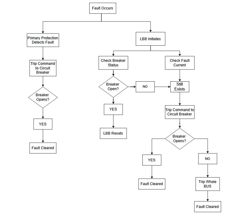
Step By Step LBB Protection Strategy
STEP 1: Fault Occurs and LBB Initiates
When a fault occurs, the fault current rises and exceeds the LBB relay pickup threshold setting. The LBB relay becomes active and starts monitoring the system. It does NOT take immediate action for 200-300 ms (as per relay settings) but simply observes whether primary protection can handle the fault.
- Fault current exceeds threshold
- LBB relay activates
- Monitoring begins
- Waits for primary protection response
STEP 2: Primary Protection
The primary protection relay detects the fault using its own logic (distance, differential, or overcurrent relay) and issues a trip command to the circuit breaker within approximately 50 milliseconds.
- Primary relay detects fault
- Issues trip command to breaker
- Breaker should respond within 25-75 ms
STEP 3: LBB Checks Two Conditions
LBB relay continuously monitors two things:
- Check 1: Breaker auxiliary contact (OPEN or CLOSED?)
- Check 2: Fault current level (GONE or STILL HIGH?)
STEP 4: If Primary Protection Works
If breaker auxiliary contact is OPEN AND fault current is GONE, primary protection has worked successfully. LBB relay resets and waits for the next fault. The entire fault is cleared in 75-100 milliseconds with only one breaker disconnected (selective protection).
STEP 5: If the Primary Protection Does Not Work or Breaker is Still Closed
If breaker auxiliary contact is CLOSED OR fault current is still HIGH after primary relay’s trip command, primary protection has failed to operate the breaker. LBB relay detects this failure and activates its backup tripping sequence.
STEP 6: Force-Trip Attempts from LBB Relay (100-200 ms Intervals)
LBB sends its own trip signals to the same breaker at 100-200 millisecond intervals.
First attempt at ~150 ms, second attempt at ~250 ms.
This re-energizes the breaker trip coil to force it open. Some temporary failures (hydraulic stiction, capacitor discharge) can be overcome by multiple tripping attempts.
STEP 7: If Tripping from LBB Works
If breaker opens during one of the force-trip attempts from LBB relay and the fault current drops to zero and is completely cleared, LBB resets.
- Breaker opens from force-trip
- Fault current drops to zero
- Fault cleared in 200-300 ms
- Only one breaker disconnected
- LBB resets
- Selective protection maintained
STEP 7: If Breaker is Still Closed (Tripping from LBB did not work)
After all force-trip attempts have been exhausted (approximately 300 milliseconds), if breaker auxiliary contact is still CLOSED and fault current is still HIGH, LBB concludes the breaker has a permanent mechanical failure. The breaker cannot respond to any electrical signal.
STEP 8: Wide-Spread Bus Isolation
LBB Relay sends trip commands to ALL breakers connected to the bus (both incoming and outgoing feeders). The entire bus becomes de-energized and isolated. Fault is completely cleared in 400-450 milliseconds (guaranteed).
Key Points:
- Trip ALL breakers on faulted bus
- Trip ALL incoming supply breakers
- Entire bus de-energized
- Complete isolation achieved
- Fault cleared in 400-450 ms
- GUARANTEED clearing
Summary: The Three Possible Outcomes
| Outcome | Tripping Time | Cause | Result |
|---|---|---|---|
| Primary Protection Works | 75-100 ms | Breaker opens normally | 1 breaker off (selective) |
| Force-Trip from LBB Works | 200-300 ms | Temporary failure overcome | 1 breaker off (selective) |
| Bus Isolation | 400-450 ms | Permanent mechanical failure | All breakers connected to the Bus is off |
LBB Relay CT Input, Binary Input and Output Circuit
Local Breaker Back Up (LBB) relay protection requires precise integration of input and output circuits to function effectively.
Below are some images showing the LBB relay CT, Binary Input & Output Circuit.
The relay receives fault current measurements from Current Transformers, monitors system status through binary inputs, and issues control signals through output contacts.
These three interconnected circuits work together to detect breaker failures and execute protective actions within milliseconds to clear faults and isolate equipment.
LBB Relay CT Input Circuit
The below images shows three Current Transformers (R, Y, B phases) measure fault currents. CT secondary outputs connect to relay input coils (IA, IB, IC). Each phase current is independently measured and monitored to detect faults and verify fault clearing. This allows the relay to determine whether fault current has dropped to normal levels after breaker operation.

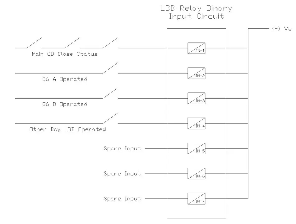
LBB Relay Binary Input Circuit
As shown below, the LBB relay receives seven binary inputs. IN-1 detects main circuit breaker close status. IN-2 shows 86A relay operation (protection function A). IN-3 indicates 86B relay operation (protection function B). IN-4 signals other bay LBB operation. IN-5, IN-6, and IN-7 are spare inputs for future expansion and additional monitoring requirements.
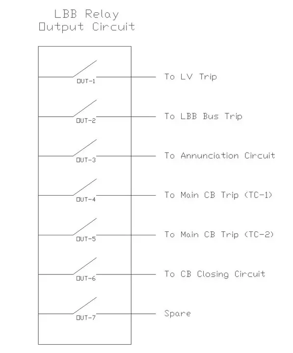
LBB Relay Binary Output Circuit
As shown in the image below, the LBB relay contains six output contacts for controlling protective actions. OUT-1 sends Low Voltage (LV) trip signals. OUT-2 triggers LBB bus isolation by tripping all connected breakers. OUT-3 activates annunciation circuits for alarm indication. OUT-4 and OUT-5 provide dual trip signals to main circuit breaker trip coils (TC-1 and TC-2). OUT-6 controls breaker closing circuits.
Why LBB Protection is Essential
To understand why LBB protection is essential, consider a 220 kV transmission line with a phase-to-ground fault occurring at the sending end. The primary protective relay (distance relay Zone 1) detects the fault within 20 milliseconds and sends a trip signal to the breaker. However, due to mechanical failure, the breaker fails to open its contacts. Without LBB protection, the fault current continues flowing through the faulted line for several seconds until remote backup protection at the other end operates—typically after 1-2 seconds.
During this extended fault duration:
- Equipment windings are severely heated causing permanent damage
- Mechanical forces in equipment increase proportionally to the square of the current
- System voltage drops significantly, affecting distant loads and causing other equipment to fail
- Thermal stress on conductors can weaken insulation
With LBB protection in place, the backup function detects the breaker failure (by observing that current continues despite trip command) and operates within 500-800 milliseconds. LBB then trips all other breakers on the bus to completely isolate the faulted line, drastically reducing fault duration and equipment damage.
Practical Design and Application of LBB Protection
1. Transmission Line Protection Example
System Details:
- Voltage Level: 220 kV
- Line Length: 150 km
- Primary Protection: Distance relay with Zone 1 covering 85% of line
- LBB Strategy: Two-stage (Stage 1: force-trip; Stage 2: bus isolation)
LBB Relay Settings:
- Current pickup: 1800 A (1.5 × primary pickup of 1200 A)
- Stage 1 time delay: 100 ms (first force-trip attempt)
- Stage 1 retry interval: ~250 ms (second trip attempt)
- Stage 2 activation time: ~300 ms (if breaker auxiliary still shows closed)
- Stage 2 action: Trip all breakers on the 220 kV bus
Operating Scenario – Breaker Mechanical Failure:
Timeline:
- t = 0 ms: 3-phase fault occurs at 40 km on the line
- t = 20 ms: Distance relay detects fault
- t = 50 ms: Primary relay issues trip command to breaker
- t = 75 ms onwards: Breaker fails to open (mechanical linkage broken)
- t = 100 ms: LBB detects sustained current + breaker auxiliary still “CLOSED”
- t = 150 ms: LBB issues 2nd trip signal (Stage 1, force-trip attempt #1)
- t = 150-200 ms: Monitor auxiliary contact—still “CLOSED”
- t = 250 ms: LBB issues 3rd trip signal (Stage 1, force-trip attempt #2)
- t = 250-300 ms: Monitor auxiliary contact—still “CLOSED”
- t = 300-350 ms: LBB determines permanent mechanical failure
- t = 350 ms: LBB switches to Stage 2 and sends trip signals to:
- All outgoing 220 kV breakers (to other lines)
- All incoming breakers (supply isolation)
- t = 400-450 ms: Multiple breakers open, 220 kV bus completely isolated
- Fault Duration: ~400-450 milliseconds
2. Power Transformer Protection Example
System Details:
- Transformer Rating: 100 MVA, 220/33 kV
- Primary Protection: Differential relay
- LBB Strategy: Two-stage force-trip with faster timing
Why Transformer LBB is Faster:
Transformers have lower thermal time constants than transmission lines. Winding insulation can degrade rapidly under fault conditions.
| Aspect | Transmission Line | Power Transformer |
|---|---|---|
| Fault Current Rise Time | Slower (line impedance) | Faster (low winding impedance) |
| Equipment Thermal Limit | Longer (robust conductors) | Shorter (insulation sensitive) |
| Stage 1 Duration | 100-300 ms | 50-150 ms (FASTER) |
| Stage 2 Activation | ~300-350 ms | ~150-200 ms (FASTER) |
LBB Settings for Transformer:
- Current pickup: 150 A (for 100 MVA, this is ~1.4 × rated primary current)
- Stage 1 force-trip attempts: ~50-100 ms between attempts
- Stage 2 activation: ~150-200 ms (if auxiliary still shows closed)
- Stage 2 action: Trip HV breaker, LV breaker, and all bus breakers on both sides
Operating Scenario – Transformer Internal Fault:
- t = 0 ms: Internal fault in transformer winding
- t = 20 ms: Differential relay detects fault
- t = 70 ms: Differential relay issues trip command
- t = 75 ms onwards: Breaker fails to open (stiction/mechanical issue)
- t = 100 ms: LBB detects failure + issues 1st force-trip (Stage 1)
- t = 100-150 ms: Monitor auxiliary—if still closed, intense heating occurs
- t = 150 ms: LBB issues 2nd force-trip attempt (if needed)
- t = 150-200 ms: Monitor auxiliary—decide if Stage 2 is needed
- If still closed at 200 ms → Switch to Stage 2
- t = 200-250 ms: LBB initiates wide-spread isolation:
- Trip HV breaker
- Trip LV breaker
- Trip all other breakers on both buses
- t = 250-300 ms: Complete isolation achieved
- Fault Duration: ~200-300 milliseconds
Testing and Commissioning of LBB Protection
Secondary Injection Tests:
- Inject steady overcurrent above LBB pickup level
- Verify time delay settings (within ±5%)
- Simulate breaker auxiliary contact in “CLOSED” position
- Verify that force-trip output activates (Stage 1)
- Simulate breaker auxiliary contact remains “CLOSED” after time delay
- Verify that wide-spread trip outputs activate (Stage 2)
- Test all stage transitions and timing
Field Testing Checklist:
- Verify breaker auxiliary contacts are properly wired to LBB relay
- Test physical continuity of all trip output circuits
- Verify that force-trip signals reach the breaker correctly
- Simulate breaker failure condition and confirm LBB response
- Test that all Stage 2 trip outputs function correctly
- Verify timing of Stage 1 and Stage 2 operations
- Document all test results
Conclusion
Local Breaker Back Up (LBB) protection stands as one of the most important and cost-effective protection schemes in electrical power systems. Despite advances in communication-based protection systems and wide-area monitoring, LBB remains indispensable due to its simplicity, reliability, and independence from communication infrastructure.