Electrical power systems require sophisticated protective mechanisms to detect and isolate faults within milliseconds to prevent cascading failures and equipment damage. The Mho characteristic is one of the most important protection schemes used in modern transmission line Distance protection systems. Mho Relays employs circular characteristics in the R-X impedance plane to distinguish between fault conditions and normal operating states.
By analyzing both magnitude and phase relationships between voltage and current, Mho relays achieve excellent discrimination between three-phase faults, phase-to-ground faults, and normal load conditions.
In this technical guide we will discuss the mathematical foundations, operational principles, and practical applications of Mho characteristics in modern power systems.
What Does Mho Mean?
“Mho” is literally “Ohm” spelled backwards. This naming convention represents the mathematical reciprocal relationship between two electrical quantities.
An Ohm (Ω) measures electrical resistance (how much the material opposes the flow of electricity). A Mho (℧), also called a Siemens (S), measures conductance (how easily electricity flows through the material).
- If a component has high resistance, it conducts electricity poorly (low conductance)
- If a component has low resistance, it conducts electricity easily (high conductance)
- Mathematically: \(\text{Conductance} = \frac{1}{\text{Resistance}}\) or \(G=\frac{1}{R}\)
Consider a water distribution network to understand this relationship intuitively. A narrow, clogged water pipe offers high resistance to water flow, while a wide, clean water pipe offers low resistance to water flow. The same principle applies to electricity flowing through conductors and components in the power system.
What is Admittance?
Admittance is the term used to define the overall ability of a component or circuit to conduct electricity. It’s a more complex measure than simple conductance because it includes both resistive and reactive effects.
Key Concepts:
- \(\text{Admittance (Y)} = \frac{1}{\text{Impedance (Z)}}\) or \(Y = \frac{1}{Z}\)
- \(\text{Impedance (Z)} = \text{Resistance (R)} + \text{Reactance (X)}\)
- Admittance is the measure used by Mho relays to make protection decisions
- Instead of thinking about what blocks electricity, Mho relays think about what allows electricity to flow
How Mho Distance Relays Operate
A Mho Distance Relay continuously monitors whether the admittance (how easily electricity is flowing) at the relay location falls within a predefined circular zone.
Fundamental Logic:
- If measured admittance falls inside the circular protection zone → Fault detected → Trip the relay
- If measured admittance falls outside the circular protection zone → Normal operation → No trip
Imagine you are the chief security officer at an important facility. You establish a circular perimeter fence around the facility that defines your area of responsibility. Your security protocol is straightforward: anyone inside the fence is an unauthorized intruder requiring immediate action, while anyone outside is not your responsibility.
Similarly, the Mho relay has a circular protection zone representing its responsibility area. Faults within this zone receive immediate attention; faults outside the zone are the responsibility of other relays.
Why Circular Characteristic?
The circular characteristic of the Mho relay emerges directly from the mathematical properties of admittance measurement.
The Mathematical Origin of Circularity:
When you set a Mho relay to maintain a constant admittance value (which means constant protection reach), the mathematical relationship between voltage and current creates a specific pattern in the R-X plane.
Step-by-Step Derivation (Simplified):
Step-1: Define Admittance:
\(Y = \frac{1}{Z} = \frac{1}{(R + jX)}\)
Step-2: Express in Terms of Magnitude:
\(|Y| = \frac{1}{|Z|} = \frac{1}{\sqrt{(R^2 + X^2)}}\)
Step-3: Set Constant Magnitude:
When |Y| = constant (which is what the relay setting specifies),
we have:
\(\frac{1}{\sqrt{(R^2 + X^2)}} = k\)
Rearranging:
\(\sqrt{(R^2 + X^2)} = \frac{1}{k} = \text{constant}\)
Step-4: Square Both Sides:
\(R^2 + X^2 = (\frac{1}{k})^2 = \text{constant}\)
Step-5: The Circle Equation:
This is the equation of a circle:
\((R – 0)^2 + (X – 0)^2 = \text{radius}^2\)
However, for the practical Mho relay protection zone, a modified form emerges that produces a circle passing through the origin:
The Practical Mho Circle Equation:
\(|Z – \frac{Z_R}{2}| = |\frac{Z_R}{2}|\)
This equation is the definition of a circle in the complex plane. All points Z that satisfy this equation are equidistant from the center point \((\frac{Z_R}{2})\), and the distance from each point to the center equals the radius \((|\frac{Z_R}{2}|)\).
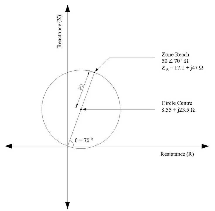
1. Circle Center Calculation
For a transmission line with reach impedance \(Z_R\), the circle center is positioned at exactly half the reach impedance:
\(\text{Center} = \frac{Z_R}{2}\)
Example Calculation:
- If reach impedance = 50∠70° Ω
- Then Z_R = 50 cos(70°) + j50 sin(70°) = 17.1 + j47 Ω
- Circle center = (17.1 + j47)/2 = 8.55 + j23.5 Ω
- In R-X coordinates: Center at (8.55, 23.5)
2. Circle Radius Calculation
The radius of the circle equals half the magnitude of the reach impedance:
\(Radius = \frac{|Z_R|}{2}\)
Example:
\(|Z_R| = 50 Ω\), so \(\text{Radius} = \frac{50}{2} = 25 Ω\)
3. Circle Always Passes Through Origin
Distance from center to origin:
\(\sqrt{((8.55 – 0)² + (23.5 – 0)²} = 25 Ω = \text{Radius}\)
This confirms the circle passes through the origin.
Properties of the Mho Circle
1. Passes Through the Origin
The circle always passes through the origin point (0, 0) on the R-X plane. This simple property has profound protective implications. The origin represents zero impedance (a fault right at the relay location). A relay that is “solid” at the origin cannot false-trip on extremely close faults.
2. Center Offset Toward Reactance
The circle center is not located at the origin but is instead offset toward positive reactance. This positioning is crucial for separating fault conditions from normal load conditions.
Transmission lines naturally have more reactance (X) than resistance (R) due to their inductance. This offset positions the circle to naturally avoid the normal load impedance locus.
Heavy loads appear at 20-40° angles, while faults appear at 70-85° angles. The offset circle naturally separates these two operating regions.
3. Directional Discrimination
The circular shape inherently provides directional capability—the relay can distinguish between faults in the forward direction and faults in the reverse direction (behind the relay).
Forward-direction faults on the protected transmission line typically fall inside the circle, while reverse-direction faults on the opposite side fall outside.
This means Mho relays don’t need separate directional units, improving protection selectivity.
Visualizing Fault Locations on the R-X Plane
Different fault locations produce different impedance values appearing as distinct points:
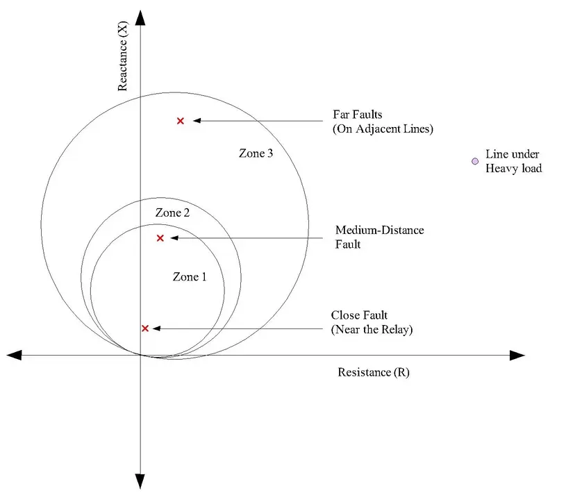
Close Faults (Near the Relay):
- Result in very low impedance values; appear near origin (0, 0)
- Example: 5 km fault might be (1.5, 8) Ohms
Medium-Distance Faults:
- Result in moderate impedance values; appear at medium distances
- Example: 100 km fault might be (6, 35) Ohms
Far Faults (On Adjacent Lines):
- Result in higher impedance values; appear at greater distances
- Example: 200 km fault might be (12, 70) Ohms
Normal Load Conditions:
- Appear in a specific region determined by load power factor
- Usually at 20-40° angle from horizontal axis
- May appear far outside all protection zones
- Example: Heavy load might be (100, 58) Ohms
How Mho Characteristics Detect Different Types of Faults
Electrical faults are classified based on which phases and grounds are involved. The detection characteristics vary depending on the fault type because each fault configuration produces a unique impedance signature in the R-X plane.
Three-Phase Balanced Faults
A three-phase fault occurs when all three phases of the transmission line come into contact with each other, or when all three phases contact ground simultaneously. This is the most severe fault condition.
Impedance Characteristics:
- Results in the lowest impedance among all fault types
- Impedance angle approximately equals the line angle (typically 70-85°)
- Appears as a point closest to the origin on the R-X plane
- Creates the highest fault current due to lowest impedance
Example:
- Line voltage: 400 kV
- Three-phase fault current: 20,000 A
- Calculated impedance: 400,000V ÷ 20,000A = 20 Ω (very low)
- Point location on R-X plane: (6.8, 18.8) – very close to origin
Mho Relay Response:
- Detected deeply inside Zone 1
- Instantaneous trip with no delay
- Fastest possible response
- Highest confidence in fault detection
Single-Phase-to-Ground Faults
A phase-to-ground fault occurs when one phase conductor comes into contact with the ground or earth. This is one of the most common fault types in power systems.
Impedance Characteristics:
- Impedance magnitude depends on ground resistance and fault location
- Typically higher impedance than three-phase faults but lower than phase-to-phase faults
- Ground resistance significantly affects the impedance magnitude
- Appears as a point at moderate distance from origin
Example:
- Single phase A to ground fault
- Fault current: 8,000 A (lower than three-phase)
- Calculated impedance: 400,000V ÷ 8,000A = 50 Ω
- Point location on R-X plane: (17.1, 47) – moderate distance
- This point is typically inside Zone 1 circle
Impact of Ground Resistance:
- Low ground resistance (1-10 Ω): Creates low-impedance fault, detected easily
- High ground resistance (50-500 Ω): Increases impedance, may approach Zone boundaries
- Very high ground resistance (1000+ Ω): May escape Zone 1, detected by Zone 2
Mho Relay Response:
- Typically detected inside Zone 1 for most conditions
- Instantaneous trip with no delay
- Good detection reliability
- May require Zone 2 backup if ground resistance is unusually high
Phase-to-Phase Faults (Without Ground Contact)
A phase-to-phase fault occurs when two phase conductors come into contact with each other without involving ground.
Impedance Characteristics:
- Impedance magnitude typically higher than single-phase-to-ground faults
- Does not involve ground resistance; impedance depends only on line parameters
- Creates intermediate fault current (lower than three-phase, higher than phase-to-phase-to-ground)
Example:
- Phase A to Phase B fault (no ground contact)
- Fault current: 12,000 A (intermediate magnitude)
- Calculated impedance: 400,000V ÷ 12,000A = 33.3 Ω
- Point location on R-X plane: (11.4, 31.2) – moderate distance
Comparison with Ground Faults:
- Phase-to-phase impedance > phase-to-ground impedance (due to absence of ground path)
- Phase-to-phase faults appear further from origin than phase-to-ground faults
- Still well inside Zone 1 for most practical applications
Mho Relay Response:
- Detected inside Zone 1
- Instantaneous trip with no delay
- Reliable detection
- Lower fault current means slightly more time for current rise but still very fast
Double-Phase-to-Ground Faults
A double-phase-to-ground fault occurs when two phases come into contact with each other AND both touch ground. This is a complex fault condition combining aspects of both phase-to-phase and phase-to-ground faults.
Impedance Characteristics:
- Impedance magnitude variable, depends on ground resistance
- Can be either lower or higher than single-phase-to-ground depending on configuration
- Impedance angle typically different from line angle due to ground involvement
- Multiple current paths create complex impedance behavior
Example:
- Phase A and Phase B both contact ground
- Fault current: 15,000 A
- Calculated impedance: 400,000V ÷ 15,000A = 26.7 Ω
- Point location: (9.1, 25.1)
Mho Relay Response:
- Detected inside Zone 1
- Instantaneous trip with no delay
- Good detection but more complex trajectory analysis needed
- May require advanced algorithms for precise characterization
Comparative Fault Analysis Table
| Fault Type | Impedance Magnitude | R-X Plane Location | Current Magnitude | Zone 1 Detection | Response |
|---|---|---|---|---|---|
| 3-Phase | Lowest (10-30 Ω) | Closest to origin | Highest (15-25 kA) | Immediate | Instantaneous Trip ⚡ |
| Phase-to-Ground | Medium (30-80 Ω) | Medium distance | Medium (8-15 kA) | Reliable | Instantaneous Trip ⚡ |
| Phase-to-Phase | Medium-High (25-60 Ω) | Medium distance | Medium-High (10-18 kA) | Reliable | Instantaneous Trip ⚡ |
| Double Phase-to-Ground | Variable (20-70 Ω) | Variable location | Medium-High (12-20 kA) | Usually | Instantaneous Trip ⚡ |
| Open Phase | Very High (open circuit) | Very far/undefined | Zero | No | No Trip |
| High Impedance Fault | Very High (100-1000+ Ω) | Far from origin | Low (1-5 kA) | May fail | Zone 2/3 Trip |
Arc Resistance and High-Impedance Faults
What is Arc Resistance?
When two electrical conductors come into contact across an air gap (rather than solid contact), an electrical arc is established. This arc creates an additional resistance in the fault circuit, known as arc resistance or arcing resistance. The arc represents a column of ionized air that conducts electricity but with significant resistance.
Characteristics of Arcing:
- Creates a glowing, high-temperature plasma channel
- Produces temperatures exceeding 5,000°C
- Adds significant resistance to the fault path
- Resistance value varies with arc length, pressure, and weather conditions
- Can range from a few Ohms to several hundred Ohms
- Increases total fault impedance, reducing fault current
High-Impedance Faults (HIF)
A high-impedance fault occurs when a conductor comes into contact with a high-resistance surface such as dry earth, wood, asphalt, or contaminated insulators. The fault current is severely limited by this high resistance.
Typical High-Impedance Fault Scenarios:
- Downed conductor on dry earth: A transmission line conductor falls to the ground in a dry area
- Contact with wood or concrete: Power line touches a dry wooden pole or concrete surface
- Contaminated insulators: Salt, dust, or pollution creates high-resistance path to ground
- Partial contact fault: Conductor touches a surface but doesn’t fully embed or make solid contact
- Arc-sustained fault: Fault is maintained by arcing rather than solid conduction
Impedance Characteristics:
- Total fault impedance: Z_fault = Z_line + Z_arc + R_ground + R_contact
- Impedance can exceed 100-1000 Ohms or more
- Fault current may be extremely low (1-5 A instead of typical thousands of Amperes)
- Impedance point appears far from origin on R-X plane
- May appear outside Zone 1 protection in standard relays
How Mho Characteristics Handle High-Impedance Faults
The Mho relay’s circular characteristic provides superior coverage for high-impedance faults compared to other relay types. The circular shape covers both resistance and reactance directions simultaneously.
The Mho circle naturally accommodates impedance variations. Even with high resistance, the fault point typically stays within the circle.
Example – Downed Conductor Fault:
- Line impedance: 50 Ω
- Arc resistance: 50 Ω
- Ground resistance: 100 Ω
- Total impedance: 200 Ω (very high)
Detailed Calculation:
- Resistive portion: Z_line_R + Z_arc_R + R_ground = 17.1 + 17 + 100 = 134.1 Ω
- Reactive portion: Z_line_X + Z_arc_X = 47 + 17 = 64 Ω
- Total impedance: √(134.1² + 64²) = 148.6 Ω
- Point on R-X plane: (134.1, 64)
Zone Assessment:
- Zone 1 circle: Center (8.55, 23.5), Radius 25 Ω
- Distance to point: √[(134.1-8.55)² + (64-23.5)²] = 132.3 Ω
- Result: Outside Zone 1, likely outside Zone 2
- May be detected by Zone 3 after 1 second delay
- Or may require dedicated high-impedance fault detection algorithms
Mho Relay Response to HIF:
- Standard Mho circles: May not detect very high-impedance faults in Zone 1
- Advanced Mho with adaptive reach: Can expand Zone 1 to detect more high-impedance faults
- Supplementary HIF detection: Modern relays include separate algorithms for high-impedance detection
- Time-based detection: Zone 2/3 may eventually detect persistent HIF
Modern Solutions for High-Impedance Fault Detection
1. Resistance Tolerance Circles:
Modern numerical Mho relays implement resistance tolerance circles (also called resistance-limited circles) that extend the protection characteristic in the horizontal (resistance) direction.
This allows detection of faults with resistance up to 25-40 Ω, creates an extended characteristic covering more of the R-X plane, balances between sensitivity and security, and prevents false trips while catching high-resistance faults.
2. Impedance Locus Analysis:
Advanced relays analyze the trajectory of the impedance point. Faults show characteristic movement patterns into the circle, load conditions show different patterns (usually stay outside), power swings show oscillating patterns (move in and out), and this allows more sophisticated discrimination algorithms.
Detection Reliability of Mho Relay by Fault Type
Three-Phase Faults:
- Detection probability: ~99.9% (Excellent)
- Reason: Very low impedance, well inside all zones
- Reliability: Highest among all fault types
Phase-to-Ground Faults:
- Detection probability: ~99% (Excellent)
- Reason: Low impedance, typically inside Zone 1
- Reliability: Excellent except for very high ground resistance
Phase-to-Phase Faults:
- Detection probability: ~98% (Excellent)
- Reason: Moderate impedance, inside Zone 1
- Reliability: Very high, no ground resistance variation
High-Impedance Faults:
- Detection probability: ~60-80% (Moderate)
- Reason: May exceed Zone 1 reach, delayed detection
- Reliability: Depends on fault type and conditions; Zone 3 provides backup
Practical Fault Detection Scenarios
Scenario 1: Lightning-Induced Three-Phase Fault
Initial Conditions:
- Transmission line voltage: 400 kV
- Line impedance: 50 ∠ 70° Ω
- Lightning strikes with extreme voltage, creating phase-to-phase arcing
Fault Development:
- Lightning creates initial arc between Phase A and Phase B
- Arc quickly bridges to Phase C (all three phases involved)
- Arc resistance: ~20 Ω initially
- Three-phase fault established
Impedance Evolution:
- t = 0 ms: Lightning impact, transient impedance very low
- t = 2 ms: Arc stabilizes, impedance = 15 ∠ 70° Ω
- t = 10 ms: Steady-state impedance = 15 ∠ 70° Ω (5.1 + j14.1)
- Location on R-X plane: (5.1, 14.1) – very close to origin
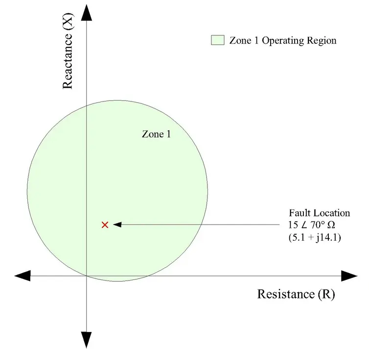
Mho Relay Detection:
- Distance from Zone 1 center (8.55, 23.5) to fault point (5.1, 14.1) = 12.8 Ω
- Zone 1 radius: 25 Ω
- Result: 12.8 < 25 → INSIDE ZONE 1 ✓
- Trip decision: Instantaneous
- Trip time: 0.04-0.08 seconds
- Outcome: Fault isolated before damage escalates
Scenario 2: Contaminated Insulator (High-Impedance Fault)
Initial Conditions:
- Transmission line: 150 kV
- Line impedance: 30 ∠ 75° Ω
- Contaminated insulator stack (salt deposit)
Fault Development:
- Salt deposit creates conductive path
- Partial arc develops across contaminated surface
- Arc resistance: ~200 Ω
- Moisture increases conductivity, sustaining the arc
Impedance Calculation:
- Line impedance: 30 ∠ 75° = 7.76 + j29 Ω
- Arc impedance: 200 Ω (mostly resistive) = 197 + j35 Ω
- Ground impedance (dry earth): 150 Ω = 150 Ω
- Total impedance: √[(7.76+197+150)² + (29+35)²] ≈ 365 Ω
Point on R-X plane: (354.76, 64)
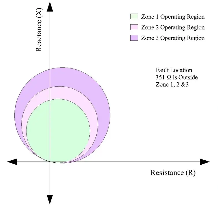
Mho Relay Detection:
- Distance from Zone 1 center: ~351 Ω
- Zone 1 radius: 15 Ω
- Result: 351 >> 15 → OUTSIDE ZONE 1 ✗
- Zone 1: No detection
- Zone 2 (reach ~36 Ω): OUTSIDE ZONE 2 ✗
- Zone 3 (reach ~45 Ω): OUTSIDE ZONE 3 ✗
Practical Outcome:
- Standard Mho relay fails to detect this high-impedance fault
- Requires supplementary algorithms such as harmonics detection, transient detection, continuous current monitoring
- Zone 3 relay on downstream circuit may eventually detect when fault current flows through it
Scenario 3: Partially Grounded Phase (Variable Impedance)
Initial Conditions:
- Transmission line: 220 kV
- Line impedance: 40 ∠ 72° Ω
- Phase A conductor partially embedded in wet soil
Fault Development:
- Conductor makes partial contact with moist soil
- Initial arc (dry conditions): ~100 Ω
- Rain increases conductivity: ~50 Ω
- Conductor settles deeper: ~20 Ω
- Fault impedance decreases over time as moisture increases
Impedance Trajectory:
- t = 0 s: 100 Ω resistive arc → Point at (100, 0)
- t = 30 s: Moisture increases → Impedance = 50 + j20 Ω
- t = 60 s: Better contact → Impedance = 34 + j40 Ω
- t = 90 s: Very good contact → Impedance = 14 + j34 Ω
Zone 1 Detection (Center 8.55, 23.5; Radius 20):
- t = 0 s: Distance = 91.5 Ω → Outside (no detection)
- t = 30 s: Distance = 41.6 Ω → Outside
- t = 60 s: Distance = 27.8 Ω → Outside
- t = 90 s: Distance = 11.9 Ω → INSIDE ✓
Mho Relay Response:
- Initially: No detection (fault impedance too high)
- After 60-90 seconds: Impedance decreases as moisture increases
- Detection when impedance finally enters Zone 1
- Total detection time: 1-2 minutes
- Drawback: Long delay before protection operates
- Solution: Supplementary algorithms monitor impedance trajectory; continuous low current triggers alarm
Fault Detection Algorithm
Multi-Parameter Fault Detection
Modern Mho relays use sophisticated algorithms that analyze multiple parameters simultaneously:
Parameters Monitored:
- Impedance magnitude: Distance from origin
- Impedance angle: Angle relative to R-axis
- Rate of change: dZ/dt (how fast impedance changes)
- Harmonic content: Presence of distorted waveforms
- Current magnitude: How much current is flowing
- Voltage magnitude: How much voltage is present
- Power factor: Relationship between voltage and current
- Trajectory: Path impedance point traces on R-X plane
Fault Signature Recognition:
- Each fault type has characteristic signatures
- Algorithms learn typical patterns
- Can distinguish between faults (sharp impedance change into zone), load changes (gradual impedance movement), power swings (oscillating impedance), inrush currents (special transformer behaviors)
Transient vs. Steady-State Analysis
Transient Analysis (First Few Milliseconds):
- Initial impedance calculation may be inaccurate
- Capacitive and inductive effects dominate
- Current rise may not yet be established
- Useful for detecting fault inception moment
Steady-State Analysis (After Stabilization):
- More reliable impedance measurement
- Better for Zone reach decisions
- Impedance settles to predictable value
- Used for determining trip location
Practical Implementation:
The relay waits 5-10 power cycles (100-200 ms at 50 Hz) for transients to settle, then evaluates steady-state impedance, balancing speed with accuracy.
Conclusion
The Mho characteristic represents more than just a technical feature of distance relays—it embodies fundamental principles of electrical protection that have evolved over decades and continue to be the industry standard. The circular Mho characteristic emerges naturally from admittance mathematics as a mathematical necessity.
In our increasingly complex electrical world, the Mho characteristic continues to provide reliable, coordinated protection.