Electric motors are the backbone of industrial operations. They power pumps, compressors, conveyors, and countless other machines. However, motors face various threats during operation. These threats include overloading, short circuits, phase failures, and locked rotor conditions. Without proper protection, these faults can damage expensive motors and cause production losses. This is where Motor Protection Circuit Breakers come into the picture.
A Motor Protection Circuit Breaker is a specialized protective device designed specifically for motor circuits. It combines the functions of a contactor, overload relay, and short circuit protection in a single unit. MPCBs have become a standard choice in motor control centers and industrial panels worldwide.
In this technical guide, we will discuss the working principle, types, components, specifications, ratings, applications and standards. We will also compare motor protection circuit breakers with other type of circuit breakers for better understanding.
1. What is a Motor Protection Circuit Breaker (MPCB)?
A Motor Protection Circuit Breaker is a type of circuit breaker built to protect electric motors from damage. It acts as a switching device and a protective device at the same time. The MPCB can manually start and stop the motor. It can also automatically disconnect the motor when a fault occurs.
The primary job of an MPCB is to protect motors against overload currents and short circuit currents. When the current exceeds safe limits, the MPCB trips and disconnects the motor from the power supply. This prevents overheating, insulation damage, and fire hazards.
MPCBs are manufactured according to international standards like IEC 60947-4-1 and UL 508. These standards define the performance requirements and testing procedures for motor protection devices.
2. How Does an MPCB Work?
The working principle of an MPCB involves two separate protection mechanisms. These are thermal protection and magnetic protection. Both mechanisms work together to provide complete motor protection.
2.1 Thermal Protection (Overload Protection)
The thermal protection mechanism uses a bimetallic strip. This strip is made of two different metals bonded together. Each metal has a different thermal expansion rate. When excess current flows through the MPCB, it generates heat. This heat causes the bimetallic strip to bend.
When the strip bends far enough it triggers the trip mechanism. The tripping time depends on the amount of overload. A small overload takes longer to trip the MPCB and a large overload trips it faster. This behavior matches the thermal characteristics of motors.
For example, if a motor rated for 10 amperes runs at 12 amperes, the MPCB will trip after several minutes. If the current rises to 15 amperes, the tripping time reduces to seconds. This inverse time characteristic allows motors to handle normal starting currents without false tripping.
2.1 Magnetic Protection (Short Circuit Protection)
The magnetic protection mechanism uses an electromagnetic coil. When a short circuit occurs, the current rises instantly to very high levels. This high current creates a strong magnetic field in the coil. The magnetic force trips the breaker immediately.
The magnetic trip operates in milliseconds. It protects the motor and wiring from the destructive effects of short circuit currents. Without this fast-acting protection, cables could melt and equipment could catch fire.
3. Construction and Components of MPCB
An MPCB consists of several internal components working together. Each component has a specific function in the protection and operation of the device.
3.1 Outer Housing (Enclosure)
The outer housing is the external body of the MPCB. It is made from high-grade thermoplastic or thermoset materials. These materials can withstand high temperatures and provide excellent electrical insulation. The housing protects internal components from dust, moisture, and mechanical damage. It also contains the arc safely during fault interruption.
The housing is designed to be flame retardant according to UL94 V-0 standards. Mounting features like DIN rail clips or screw holes are integrated into the housing design.
3.2 Main Contacts
Main contacts are the primary current-carrying elements of the MPCB. They are made from silver alloy or silver-cadmium oxide materials. These materials offer low electrical resistance and high resistance to welding under fault currents.
The contacts consist of fixed contacts and moving contacts. During normal operation, the contacts remain closed and carry motor current. When a fault occurs, the contacts separate to interrupt the circuit.
3.3 Contact Spring Assembly
The contact spring assembly provides the pressure needed to keep the main contacts firmly closed. It uses compression springs or leaf springs mounted behind the moving contacts. Proper contact pressure is important for low resistance connections. Insufficient pressure causes overheating at the contact interface. The springs maintain consistent pressure throughout the MPCB operating life. During opening, the springs help accelerate contact separation.
3.4 Bimetallic Strip (Thermal Element)
The bimetallic strip is the heart of the overload protection system. It is made by bonding two metal strips with different thermal expansion coefficients. Common material combinations include invar and brass or iron and nickel alloys.
When overload current flows, the strip heats up and bends due to unequal expansion. This bending action triggers the trip mechanism after a time delay. The delay is inversely proportional to the overload magnitude. The bimetallic strip provides inverse time characteristics that match motor thermal behavior.
3.5 Magnetic Trip Coil (Electromagnetic Element)
The magnetic trip coil provides instantaneous short circuit protection. It consists of a copper coil wound around a magnetic core. During normal operation, the magnetic field produced is not strong enough to trigger the trip mechanism. When a short circuit occurs, the current rises rapidly to many times the normal value. This creates a strong magnetic field that pulls the armature. The armature movement triggers the trip mechanism immediately. The magnetic trip operates in milliseconds to protect against high fault currents.
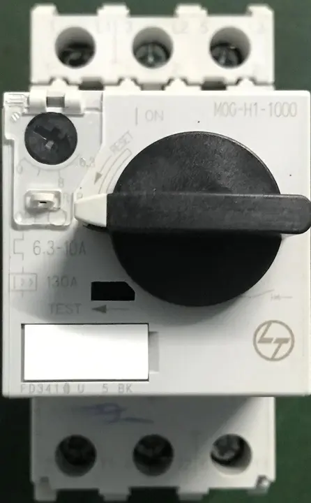
3.6 Current Adjustment Dial
The current adjustment dial is located on the front panel of the MPCB. It allows users to set the overload trip current within the rated range. The dial is marked with current values in amperes. Rotating the dial changes the position of the bimetallic strip relative to the trip mechanism. This adjusts the bending distance required to trip the MPCB. The adjustment range is usually about 40% to 100% of the maximum rated current. Some MPCBs use a rotary knob while others use a slider mechanism.
3.7 Operating Handle
The operating handle is the manual control interface of the MPCB. It protrudes through the front panel of the housing. The handle has three positions: ON, OFF, and TRIPPED. Moving the handle to ON closes the main contacts. Moving it to OFF opens the contacts for isolation. After a fault trip, the handle moves to a middle TRIPPED position.
This visual indication tells operators that a fault has occurred. To reset, the handle must be moved to OFF first, then back to ON. Some handles include padlock provisions for lockout-tagout procedures.
3.8 Arc Chutes (Arc Extinguishing Chamber)
Arc chutes are placed around the main contact area. When contacts separate under load, an electric arc forms between them. The arc chute consists of multiple steel or copper plates arranged in a stack. These plates are called arc splitters or deion plates. The arc is drawn into the chute by magnetic forces and hot gas movement. Inside the chute, the arc is split into multiple smaller arcs. Each plate cools a portion of the arc. This cooling effect lengthens and extinguishes the arc quickly. Proper arc extinction prevents contact damage and fire hazards.
3.9 Auxiliary Contact Block
The auxiliary contact block contains additional contacts for control and indication purposes. These contacts operate together with the main contacts but carry only signal-level currents. Auxiliary contacts are available in normally open (NO) and normally closed (NC) configurations. They are used to signal the MPCB status to external devices.
4. Specifications of an MPCB
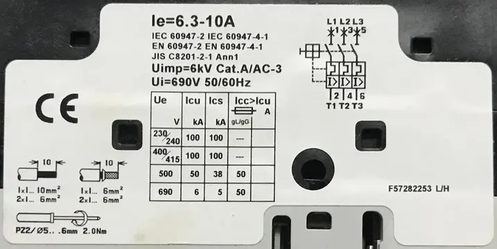
The image shows the nameplate of a Motor Protection Circuit Breaker (MPCB). This small label contains almost all the technical data you need to select and apply the device correctly.
At the very top is the current setting: Ie = 6.3–10 A. Ie is the rated operational current of the MPCB for motor duty (AC‑3). The adjustable thermal release inside the breaker can be set anywhere between 6.3 A and 10 A to match the motor’s full‑load current.
Just below this are the standards the device complies with: IEC 60947‑2 (circuit‑breakers) and IEC 60947‑4‑1 (contactors and motor‑starters), together with the corresponding EN and JIS numbers. This tells you the breaker has been tested for both short‑circuit protection and motor‑starter functions according to internationally recognised rules.
Next come the voltage and utilization ratings:
- Uimp = 6 kV – rated impulse withstand voltage. The MPCB can withstand surge overvoltages up to 6 kV (e.g. lightning or switching transients).
- Cat. A / AC‑3 – “Category A” means there is no intentional short‑time delay for short‑circuit currents; it trips instantaneously. “AC‑3” is the utilization category for starting and stopping squirrel‑cage induction motors.
- Ui = 690 V, 50/60 Hz – rated insulation voltage. The insulation system is designed for networks up to 690 V at either 50 or 60 Hz.
In the centre is the short‑circuit performance table. Ue is the rated operational voltage; Icu is the ultimate breaking capacity; Ics is the service breaking capacity.
- At 230/240 V and 400/415 V, the MPCB can interrupt 100 kA fault current (Icu) and remain in service at the same level (Ics = 100 kA).
- At 500 V, both Icu and Ics are 50 kA.
- At 690 V, Icu is 6 kA and Ics is 5 kA. The last column, Icc > Icu (gL/gG) = 50 A, indicates that with an upstream 50 A gL/gG fuse, the overall short‑circuit capacity of the combination exceeds the breaker’s own Icu.
On the right is the wiring diagram. Terminals L1, L2, L3 at the top are the line (supply) connections, numbered 1–3–5. Terminals T1, T2, T3 at the bottom (2–4–6) feed the motor. The symbol block shows the three poles and the common trip mechanism that opens all phases simultaneously when a fault occurs.
5. Types of Motor Protection Circuit Breakers
MPCBs come in different types based on their features and applications. Here are the main categories.
5.1 Standard Thermal-Magnetic MPCB
The standard thermal-magnetic MPCB is the most common type used in industrial applications. It combines both thermal overload protection and magnetic short circuit protection in one device. This combination provides complete motor protection against both slow-developing overloads and sudden short circuits. Standard thermal-magnetic MPCBs are suitable for most general-purpose motor applications in manufacturing plants and commercial buildings.
Key Features
- Dual protection mechanism
- Adjustable overload current setting
- Fixed magnetic trip point
- Wide range of current ratings available
- Cost-effective solution for most applications
Applications
- General industrial motors
- Pump motors
- Fan and blower motors
- Conveyor drive motors
- Compressor motors
5.2 Magnetic Only MPCB
Magnetic only MPCBs provide instantaneous short circuit protection without thermal overload protection. They use only the electromagnetic trip mechanism. These devices are used with separate thermal overload relays for complete motor protection. The magnetic only MPCB handles the high-speed short circuit interruption while the overload relay provides adjustable thermal protection. This combination offers more precise overload settings than a standard MPCB can provide.
Key Features
- Instantaneous magnetic trip only
- No thermal overload element
- High breaking capacity for fault currents
- Used with external overload relay
- Adjustable or fixed magnetic trip setting
Applications
- Installations with electronic overload relays
- Combination starters with separate overload relays
- Applications requiring Class 10 or Class 20 overload protection
- Motor circuits needing precise overload adjustment
5.3 MPCB with Phase Failure Protection
This advanced MPCB type includes built-in phase failure detection circuit. It monitors all three phases for presence, sequence, and balance. When one phase is lost, the MPCB trips to protect the motor from single-phasing damage. Single-phasing causes the motor to draw excessive current on the remaining phases. This leads to rapid overheating and winding damage. The phase failure protection trips faster than thermal protection alone would respond. Some models also detect phase reversal which can damage certain motor-driven equipment like pumps and compressors.
Key Features
- Built-in phase monitoring circuitry
- Detects phase loss condition
- May include phase reversal detection
- Faster response than thermal protection alone
- Adjustable sensitivity settings on some models
Applications
- Applications where single-phasing is a known risk
- Submersible pump motors
- Critical process motors
- Motors in remote locations
- Three-phase motors without phase monitoring relay
5.4 MPCB with Earth Fault Protection
MPCBs with earth fault protection can detect current leakage to ground. They include a residual current sensing mechanism similar to an RCD or ELCB. When current flows to ground through a fault path, the MPCB detects the imbalance and trips. This protection helps prevent electric shock hazards and equipment damage from insulation faults.
The earth fault sensitivity is adjustable from 30mA to 500mA. Lower settings provide personnel protection while higher settings provide equipment protection. This type eliminates the need for a separate earth leakage relay.
Key Features
- Residual current detection mechanism
- Adjustable earth fault sensitivity
- Combines motor protection with earth fault protection
- Test button for periodic function verification
- May include time delay setting
Applications
- Swimming pool and fountain pump motors
- Motors in wet or damp locations
- Portable motor-driven equipment
- Motors accessible to untrained personnel
- Applications requiring ground fault protection
5.5 Electronic MPCB
Electronic MPCBs use microprocessor-based protection instead of electromechanical elements. Current transformers measure the motor current and feed signals to an electronic circuit. The microprocessor analyzes the current and makes trip decisions based on programmed settings. Electronic MPCBs offer more precise protection characteristics than thermal-magnetic types.
They can implement multiple protection functions including overload, short circuit, phase failure, and ground fault. Many electronic MPCBs include communication ports for connection to building management or SCADA systems.
Key Features
- Microprocessor-based protection logic
- Digital current measurement
- Multiple adjustable protection settings
- LED display for current and status indication
- Communication capability (Modbus, Profibus, etc.)
Applications
- Smart building installations
- Critical process motors
- Motors requiring precise protection coordination
- Automated facilities with central monitoring
- Applications needing data logging
5.6 MPCB for Single Phase Motors
Single phase MPCBs are designed specifically for single phase motor protection. They have two poles instead of three poles found in three phase models. The protection characteristics are matched to single phase motor behavior. Single phase motors have different starting and running characteristics than three phase motors. The MPCB thermal element is calibrated for these characteristics. Some single phase MPCBs include capacitor switching contacts for capacitor-start motors.
Key Features
- Two-pole design for single phase circuits
- Protection matched to single phase motor characteristics
- Available with capacitor switching contacts
- Compact size for small panels
- Range of current ratings for various motor sizes
Applications
- Residential pool pump motors
- Commercial refrigeration compressors
- Small workshop machinery
- Agricultural irrigation pumps
- HVAC condenser fan motors
6. Features of MPCB
Modern MPCBs come with several features that make them suitable for motor protection.
- Adjustable Current Setting: Most MPCBs allow adjustment of the overload trip current. The setting range is marked on the device. Users can rotate a dial to select the current that matches their motor rating.
- Trip-Free Mechanism: The trip-free mechanism prevents holding the contacts closed during a fault. Even if someone holds the operating handle in the ON position, the MPCB will still trip on a fault. This safety feature protects both the motor and the operator.
- Manual and Automatic Operation: MPCBs can be operated manually using the front handle. They also operate automatically during fault conditions. This dual operation mode makes them versatile.
- Visual Trip Indication: When an MPCB trips, the operating handle moves to a middle position. This position is different from both ON and OFF. It tells operators that a fault has occurred. Some MPCBs also have a separate trip indicator window.
- Reset Function: After a trip, the MPCB can be reset manually. The operator moves the handle to the OFF position first. Then they can switch it back to ON. If the fault still exists, the MPCB will trip again.
- Compact Size: MPCBs combine multiple protection functions in one compact unit. They save panel space compared to using separate devices for each function.
7. How to Select the Right MPCB
Selecting the correct MPCB for your application requires attention to several factors. Here is a step-by-step guide.
Step 1: Determine the Motor Full Load Current
The first step is finding the motor full load current from the nameplate. Every motor has a nameplate showing rated current in amperes. This value indicates the current drawn during normal full load operation.
For example, a 5 HP three-phase motor operating at 415V draws around 7.5 amperes at full load. Record this value before selecting your MPCB.
Step 2: Select the Current Setting Range
Choose an MPCB with an adjustment range that covers your motor full load current. The FLC should ideally fall in the middle portion of the range. This allows adjustment in either direction if needed. For a motor with 7.5A full load current, select an MPCB with a range of 6 to 10 amperes for optimal setting flexibility.
Step 3: Consider the Starting Current
Electric motors draw high inrush current during startup. This starting current ranges from 6 to 8 times the full load current depending on motor design. The MPCB thermal element must allow this temporary current surge without nuisance tripping. The built-in time delay characteristic permits normal starting currents to flow for several seconds before any trip action occurs.
Step 4: Check the Breaking Capacity
The MPCB breaking capacity must exceed the prospective fault current at the installation location. Fault current depends on transformer size and cable impedance. Obtain the fault level from system studies or utility information. If the prospective fault current is 15 kA, select an MPCB rated for at least 15 kA or higher to safely interrupt faults.
Step 5: Consider the Voltage Rating
The MPCB voltage rating must match or exceed your electrical system voltage. Single-phase systems commonly use 230V rated MPCBs. Three-phase industrial systems require 415V or 690V rated devices depending on the country and application. Using an MPCB with insufficient voltage rating can cause insulation breakdown and dangerous failures during operation or fault conditions.
Step 6: Check the Operating Conditions
Ambient temperature affects MPCB thermal element performance. High temperatures cause the bimetallic strip to trip at lower currents than the dial setting indicates. When installing MPCBs in hot environments above 40°C, apply derating factors from manufacturer tables. Some MPCB models include built-in temperature compensation that automatically adjusts for ambient temperature variations up to 60°C.
Step 7: Consider Coordination
Protection coordination means the device nearest to a fault should trip first. The MPCB must coordinate with upstream breakers and downstream devices. Proper coordination prevents the main breaker from tripping when a single motor faults. Review time-current curves of all protective devices in the circuit. This analysis confirms that only the affected motor circuit disconnects during a fault.
8. MPCB vs MCB: What is the Difference?
Many people confuse MPCBs with MCBs. While both are circuit breakers, they serve different purposes.
- MCB (Miniature Circuit Breaker) is designed for general circuit protection. It protects cables and equipment from overload and short circuit. MPCB is designed specifically for motor protection. It handles the unique characteristics of motor circuits.
- MCBs have fixed current ratings. You cannot adjust the trip current. MPCBs have adjustable current settings. You can set the trip current to match your specific motor.
- Motors draw high inrush current during starting. MCBs may trip on motor starting current. MPCBs are designed to handle motor starting currents without nuisance tripping.
- MCB trip characteristics (B, C, D curves) are fixed. MPCB thermal characteristics are specifically tuned for motor protection. The magnetic trip point in MPCBs is set higher to handle motor starting current.
- MCBs are used in residential and commercial distribution boards. MPCBs are used in industrial motor control circuits.
9. MPCB vs MCCB: What is the Difference?
MPCBs and MCCBs are both used in industrial applications. However, they have different designs and purposes.
- MCCB (Molded Case Circuit Breaker) is a general-purpose industrial circuit breaker. It protects cables and equipment in power distribution systems. MPCB is specifically designed for motor protection.
- MCCBs have thermal-magnetic protection but may not have the same adjustability as MPCBs. MPCBs offer precise adjustment for motor full load current.
- MPCBs are optimized to handle motor starting conditions. MCCBs may require additional settings or accessories for motor applications.
- MCCBs are available in higher current ratings, up to several thousand amperes. MPCBs are available in lower current ratings, suitable for motor circuits.
- MPCBs are generally more economical than MCCBs for motor protection applications.
10. Advantages of Using MPCB
MPCBs offer many benefits for motor protection applications.
- Space Saving: An MPCB combines short circuit protection, overload protection, and switching function in one device. This saves panel space compared to using separate components.
- Cost Effective: Using one MPCB is often cheaper than buying a separate MCB, contactor, and overload relay.
- Easy Selection: MPCBs are available in a wide range of current settings. Selecting the right one for your motor is straightforward.
- Quick Installation: With fewer components and connections, MPCB installation is faster. This reduces labor time and costs.
- Reliable Protection: MPCBs provide coordinated thermal and magnetic protection designed for motor applications.
- Easy Maintenance: With fewer components, there is less that can go wrong. Maintenance and troubleshooting are simpler.
- Manual Control: The operating handle allows local manual control of the motor circuit.
11. Disadvantages of MPCB
Despite their benefits, MPCBs have some limitations.
- Limited Control Features: MPCBs provide basic ON/OFF control. For advanced control like reversing or speed control, additional components are needed.
- Limited Adjustability Range: Each MPCB has a limited current adjustment range. If the motor changes, a different MPCB may be needed.
- No Remote Operation: Standard MPCBs cannot be operated remotely. For remote switching, a contactor is still needed in the circuit.
- Lower Breaking Capacity: Some MPCBs have lower breaking capacities than MCCBs. This may limit their use in high fault current systems.
12. MPCB Installation
Proper installation is important for MPCB performance and safety.
Step 1 (Isolate Power): Ensure the main power supply is completely isolated and locked out before starting any installation work to prevent electrical shock or injury.
Step 2 (Verify Ratings): Verify the MPCB specifications match the motor’s voltage and current requirements.
Step 3 (Mount Device): Securely mount the MPCB onto the standard DIN rail or panel using appropriate screws.
Step 4 (Prepare Wires): Strip the insulation from the line and load wires carefully to the recommended length.
Step 5 (Connect Supply): Insert the incoming power cables into the line terminals (L1, L2, L3) and tighten the screws to the manufacturer’s specified torque settings.
Step 6 (Connect Motor): Connect the motor cables into the load terminals (T1, T2, T3) securely and check there is no physical strain or tension on connections.
Step 7 (Adjust Current): Adjust the thermal overload dial on the front face to match the motor’s full load current rating.
Step 8 (Final Inspection): Inspect all wiring connections for tightness and proper spacing, then remove any debris or tools left inside the electrical enclosure area.
Step 9 (Test Operation): Restore power to the panel, switch the MPCB handle to the “ON” position, and test the motor for correct direction and operation.
13. Maintenance of MPCB
Regular maintenance keeps MPCBs in good working condition.
- Visual Inspection: Periodically inspect the MPCB for signs of damage or overheating. Look for discoloration, melting, or burning marks.
- Connection Check: Check that all terminal connections are tight. Loose connections cause heating and can lead to failure.
- Operation Test: Manually operate the MPCB to verify proper function. The handle should move smoothly between ON and OFF positions.
- Cleaning: Keep the MPCB clean and free from dust and debris. Dust accumulation can affect heat dissipation.
- Trip Test: Some facilities perform periodic trip testing to verify protection function. This requires specialized equipment and should be done by qualified personnel.
- Replacement: Replace MPCBs that show signs of wear, damage, or malfunction. Do not attempt to repair internal components.
14. MPCB Standards and Ratings
MPCBs are manufactured and tested according to international standards.
14.1 Standards
- IEC 60947-4-1: This is the main international standard for motor starters and motor protection devices. It defines performance requirements, testing methods, and marking requirements for MPCBs.
- 1UL 508: In North America, UL 508 covers industrial control equipment including motor controllers. MPCBs sold in the US and Canada often carry UL listing.
14.2 Key Ratings
- Rated Current (In): The current the MPCB can carry continuously without tripping.
- Setting Range: The adjustable range of overload trip current.
- Breaking Capacity (Icu/Ics): The maximum fault current the MPCB can safely interrupt.
- Rated Voltage (Ue): The maximum voltage for which the MPCB is designed.
- Utilization Category: AC-3 is common for motor applications, indicating switching of squirrel cage motors.
15. Common MPCB Brands
Several manufacturers produce quality MPCBs for industrial applications.
- Siemens
- ABB
- Schneider Electric
- Eaton
- Rockwell Automation (Allen-Bradley)
- WEG
- Mitsubishi Electric
- Fuji Electric
- LS Electric
- Chint
16. Conclusion
Motor Protection Circuit Breakers are specialized devices designed to protect electric motors from overload and short circuit damage. They combine the functions of multiple devices into a single compact unit. MPCBs are widely used in industrial, commercial, and building services applications.
When selecting an MPCB, consider the motor full load current, starting current, system voltage, and available fault current. Proper installation and regular maintenance help keep MPCBs working reliably for years.
17. Frequently Asked Questions (FAQs)
MPCB stands for Motor Protection Circuit Breaker.
MCB (Miniature Circuit Breaker) is designed for general circuit protection with fixed trip ratings. MPCB is designed specifically for motor protection with adjustable current settings. MPCBs can handle motor starting currents without tripping, while MCBs may trip on high inrush currents.
MPCB can function as a local disconnect switch for motor circuits. However, it is not designed to be a main distribution switch. For main switch applications, use an appropriate MCCB or switch-disconnector.
Locate the current adjustment dial on the front of the MPCB. Find the motor full load current from the motor nameplate. Rotate the dial to match this current value.
Frequent tripping can be caused by motor overload, incorrect current setting, mechanical motor problems, high ambient temperature, or loose connections. Check each of these possibilities to identify the cause.
Standard MPCBs provide limited protection against single phasing. Some advanced MPCBs include phase failure protection. For better single-phasing protection, use an MPCB with built-in phase failure relay or add a separate phase failure relay to the circuit.
Yes, MPCB can be used without a contactor for simple on-off motor control. However, for frequent switching, remote operation, or automatic control, add a contactor to the circuit. The contactor handles frequent switching while the MPCB provides protection.
For a 5 HP three-phase motor at 415V, the full load current is approximately 7.5 amperes. Select an MPCB with a setting range that includes this value, such as 6-10A or 5-8A range. Always verify the actual motor FLC from the nameplate before selection.