Offline signature analysis is a non-destructive testing technique used to monitor the health and condition of transmission lines when they are de-energized. Think of it like taking a “digital snapshot” or “fingerprint” of your entire transmission line at a specific point in time. This technique helps you identify hidden faults, potential problems, and structural issues that could lead to line failures if left undetected.
The term “signature” refers to the unique electrical characteristics of the transmission line captured as a graph or data set. By analyzing these signatures at regular intervals and comparing them with baseline readings, maintenance teams can track how the transmission line’s condition changes over time and predict failures before they happen.
Offline signature analysis is different from real-time monitoring or online testing because it requires the transmission line to be de-energized (switched off) before testing begins. This makes it safer and allows for more detailed diagnostic analysis without the complications of live voltage affecting measurements.
Why is Offline Signature Analysis Important?
1. Early Fault Detection
One of the biggest advantages of offline signature analysis is that it can detect faults months or even years before they cause a complete line failure. Instead of waiting for your transmission line to trip unexpectedly (which disrupts power supply to consumers), you can identify problems during planned maintenance windows.
2. Cost Savings Through Preventive Maintenance
When you catch problems early, you save money by:
- Avoiding expensive emergency repairs after line failures
- Reducing unplanned outages and associated revenue loss
- Extending the operational life of transmission line equipment
- Preventing cascading failures in interconnected substations
3. Safety and Reliability
For electrical engineers and maintenance teams, safety is paramount. Offline signature analysis provides accurate fault location information (typically within ±100 meters) without requiring technicians to physically climb towers or walk the entire line length during dangerous weather conditions. This reduces occupational hazards and improves work efficiency.
4. Comprehensive Line Assessment
Unlike simple continuity tests or resistance measurements, offline signature analysis provides a complete picture of line health. It can identify:
- Exact fault locations along the entire line
- Multiple faults that may exist simultaneously
- Developing problems before they become critical
- Structural weaknesses and inhomogeneous points (areas where the line’s electrical properties are different from the rest)
How Does Offline Signature Analysis Work?
The Time Domain Reflectometry (TDR) Principle
The foundation of offline signature analysis is a technique called Time Domain Reflectometry (TDR). Here’s a simplified explanation of how it works:
- Pulse Injection: A high-frequency electrical pulse (typically above 25 kHz) is injected into one end of the transmission line.
- Pulse Travel: This pulse travels along the conductor at nearly the speed of light.
- Reflection at Discontinuities: When the pulse encounters any change in electrical impedance (resistance to electrical flow), it creates a reflection that bounces back toward the testing equipment.
- Signal Analysis: The equipment measures when the reflection arrives back and how strong it is. By knowing the speed at which the pulse travels through the conductor, technicians can calculate the exact distance to the fault or discontinuity.
- Signature Generation: All of these reflected signals are compiled into a graph or “signature” that shows what’s happening along the entire line.
Example: Imagine throwing a sound wave through a long tunnel. If there’s a wall in the middle of the tunnel, you’ll hear an echo. The time it takes to hear the echo tells you how far away the wall is. TDR works the same way with electrical pulses in transmission lines.
Frequency Domain Reflectometry (FDR) and LIRA
In addition to TDR, modern offline signature analysis also uses Frequency Domain Reflectometry (FDR) and Line Impedance Resonance Analysis (LIRA). These techniques complement TDR by:
- LIRA: Analyzes the impedance spectrum over a wide frequency band, making it particularly effective for very long cables (hundreds of kilometers) where TDR may have limitations.
- FDR: Uses multiple frequency signals to detect faults with high precision and can provide better resolution for specific fault types.
These advanced methods work together to give a complete diagnostic picture of transmission line health.
Also, read Transmission Line Continuity Test
Types of Faults Detected by Offline Signature Analysis
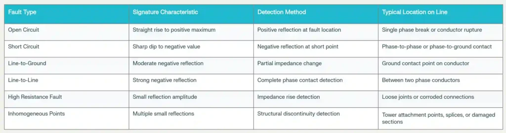
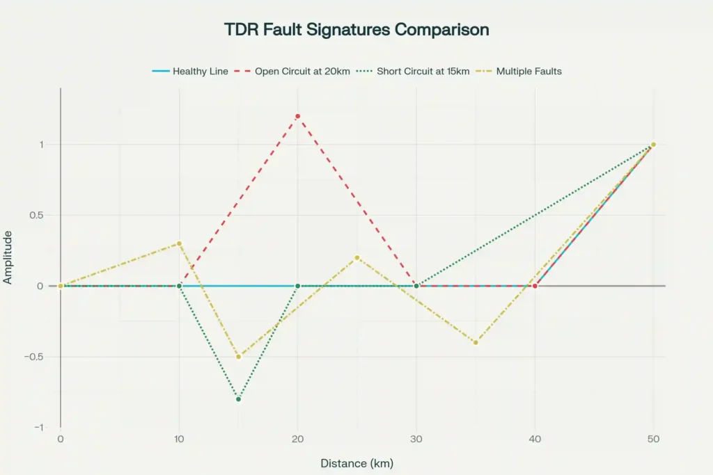
Offline signature analysis can detect virtually all types of faults that might occur in transmission lines. Each fault type produces a unique signature pattern that experienced technicians can interpret:
1. Open Circuit Faults
An open circuit fault occurs when the conductor is completely broken or disconnected, interrupting current flow. In the signature, this appears as a sharp positive reflection (an upward spike) at the location of the break.
Real-world example: A transmission line in a storm loses a conductor to wind damage. The signature shows a clear positive peak at exactly 12.5 km from the test point, pinpointing where the conductor snapped.
2. Short Circuit Faults
A short circuit fault happens when two conductors or a conductor and ground make unwanted contact. This shows up as a sharp negative reflection (a downward dip) in the signature at the fault location.
Real-world example: After heavy rain, moisture and contamination cause a phase-to-ground short at an insulator location. The signature clearly shows the negative reflection, helping maintenance crews reach and repair the exact spot quickly.
3. Line-to-Ground Faults
When a conductor touches the earth or grounding system due to insulator damage or design issues, you get a line-to-ground fault. This creates a moderate negative reflection that’s not as strong as a complete short circuit.
4. Line-to-Line Faults
These occur between two different phase conductors and produce a strong negative reflection in the signature pattern.
5. High Resistance Faults
Loose joints, corroded connections, or aging hardware create high resistance faults. These are tricky because they don’t show up as obvious sharp reflections—instead, they produce small-amplitude reflections that require careful analysis. However, identifying them early prevents catastrophic failures because loose connections generate heat that degrades insulation over time.
6. Inhomogeneous Points (Weak Links)
These are locations where the transmission line’s electrical properties change slightly—at tower attachment points, splices, sections of cable with different specifications, or areas of prior damage repair. The signature shows multiple small reflections clustered together. Monitoring these points over time helps predict when they might fail.
Offline Signature Analysis vs. Online Testing
For understanding of when to use offline testing versus online testing, it’s important to understand that they complement each other. While offline testing provides deeper diagnostic capabilities, online testing offers continuous monitoring advantages. When implementing a preventive maintenance program, many utilities use both methods strategically throughout the year to ensure optimal transmission line health and reliability.
| Aspect | Offline Signature Analysis | Online Testing |
|---|---|---|
| De-energization Required | Yes – line must be switched off | No – performed during normal operation |
| Test Voltage | Can exceed normal operating voltage | Limited to normal system voltage |
| Fault Detection Depth | Comprehensive – detects all fault types | Good – but may miss load-dependent defects |
| Time Required | 2-4 hours per line section | Real-time, continuous monitoring |
| Cost | Higher upfront (requires line outage) | Lower per test, but multiple units needed |
| Safety Setup | More complex (HV safety procedures) | Simpler setup, uses system voltage |
| Best Used For | Commissioning new lines, periodic audits | Predictive maintenance, trending over years |
Equipment Used in Offline Signature Analysis
Modern offline signature analysis relies on specialized portable equipment. The most common device is the Line Signature Analyzer (such as TAURUS MAX-3), which is a state-of-the-art testing kit designed specifically for transmission lines rated from 66 kV to 800 kV.
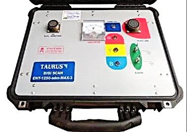
Key Components of a Signature Analyzer System
- High-Frequency Pulse Generator: Creates the initial electrical pulse that travels down the line.
- Signal Receiver: Captures the reflected signals returning from the line.
- Signal Processor: Uses advanced algorithms (often employing “multiple pulse echo correlation technique”) to process raw data and extract meaningful information.
- LCD Display: Shows real-time signature plots with distance markings in meters.
- Laptop Connectivity: Allows operators to download detailed reports, create graphics, and perform trending analysis using specialized software.
- Data Management System: Built-in software compares current signatures with baseline readings from previous tests, automatically highlighting differences and anomalies.
What You Get from the Test
After completing an offline signature analysis test, you receive:
- Line length verification (typically accurate to ±100 meters)
- Fault location and classification (showing exact fault type and distance)
- Phase sequence verification (confirming correct phase arrangement)
- Graphical signature plots showing the entire line condition
- Trend data comparing current readings with historical baselines
- Digital reports in both printed and electronic format
Step-by-Step Process: How to Perform Offline Signature Analysis
Step 1: Coordination with System Operators
- Schedule the line outage during planned maintenance windows
- Confirm the line will be isolated and grounded at both ends
- Notify all relevant personnel of the testing schedule
Step 2: Site Preparation and Safety
- Verify the line is de-energized using portable voltage indicators
- Apply proper grounding and bonding at multiple points along the line
- Set up safety cordons and danger boards at test locations
- Brief all personnel on high-voltage safety procedures
Step 3: Establish Baseline Information
- Gather the line’s designed specifications (conductor type, insulation, length)
- Collect any previous signature readings (for comparison)
- Document current line condition observations
- Record environmental conditions (temperature, humidity, weather)
Step 4: Connect Testing Equipment
- Position the Line Signature Analyzer at one end of the transmission line
- Establish proper connections between the test kit and the transmission line conductor
- Ensure all safety connections are made (grounding, bonding)
Step 5: Perform Baseline Testing
- Activate the pulse generator to inject the test signal into the line
- The equipment automatically captures reflections from the entire line length
- Typical test duration: 5-10 minutes for complete data capture
- The signature is instantly displayed on the LCD screen
Step 6: Multi-Phase Testing
For 3-phase transmission lines, repeat the signature capture for each phase individually:
- Phase A signature
- Phase B signature
- Phase C signature
Step 7: Signature Interpretation
- The baseline (should be relatively flat for a healthy line)
- Any sudden spikes (positive reflections indicating open faults)
- Any sharp dips (negative reflections indicating short circuits)
- The distance markers showing where anomalies occur
- The magnitude of reflections (stronger reflections = more serious faults)
Step 8: Fault Characterization
- Determine fault type (open, short, high resistance, etc.)
- Measure distance from test point to fault location
- Assess severity based on reflection amplitude
- Cross-reference with known tower locations and line features
Step 9: Comparative Analysis and Trending
- Compare current signatures with baseline readings from previous tests
- Identify any new faults or developing problems
- Track the progression of known issues (getting worse or stable?)
- Use the trending data to predict when maintenance is needed
Step 10: Physical Inspection at Identified Fault Locations
Before any repair work begins:
- Send a crew to the identified fault location
- Perform visual inspection to confirm the signature analysis findings
- Photograph any damage or abnormalities
- Document the actual problem and its condition
Step 11: Corrective Actions
Once the root cause is confirmed:
- Plan appropriate repairs (reclamping loose connections, replacing damaged insulators, etc.)
- Execute repairs under proper safety protocols
- Replace damaged conductor sections or hardware as needed
Step 12: Post-Repair Verification Testing
After repairs are complete:
- Perform a fresh offline signature analysis
- Confirm the fault has been successfully eliminated
- Verify the signature matches the baseline or shows expected improvement
- Document the before-and-after comparison in the maintenance record
Also, read Transmission Line Parameters Measurement
Real-World Applications and Examples
Example 1: Commissioning a New 132 kV Transmission Line
When a new 132 kV transmission line is first constructed, offline signature analysis is one of the critical commissioning tests. Before energizing the line, the Signature Analyzer is used to:
- Verify the complete line length (e.g., confirming the line is exactly 48.5 km as designed)
- Perform phase sequence testing to ensure A-B-C phase rotation is correct
- Confirm all phase-to-ground insulation is intact
- Identify any damage from installation, transportation, or weather
- Create a baseline signature for future trending
Result: The test finds that tower #23 has a loose hardware connection showing a small high-resistance reflection at 22.3 km. Repair crews fix it before energizing, preventing a future failure.
Example 2: Detecting Developing Insulator Degradation
Insulators naturally degrade over years of exposure to weather, pollution, and electrical stress. Consider a 400 kV transmission line that has been in service for 15 years:
- Year 1 Signature: Baseline established – clean, minimal anomalies
- Year 5 Signature: Small reflections appearing at tower #8 (insulator contamination starting)
- Year 10 Signature: Reflections growing stronger at same location (degradation accelerating)
- Year 15 Signature: Significant reflection now visible (insulator needs replacement)
By trending these changes, maintenance teams know to replace the insulators during the next planned outage, avoiding a catastrophic failure that could have occurred in a storm.
Example 3: Post-Storm Damage Assessment
After a severe thunderstorm, a 220 kV transmission line trips. Without signature analysis, crews would need to patrol 50 km of line looking for damage—a time-consuming and risky process. Using offline signature analysis:
- The Signature Analyzer immediately identifies an open circuit fault at 18.7 km
- Crews dispatch directly to that location
- They find a broken conductor caused by wind-blown tree branch
- Repairs are completed in hours instead of days
- Power is restored to thousands of customers quickly
Commissioning New Transmission Lines with Signature Analysis
When commissioning a new transmission line, offline signature analysis is now a standard test requirement. It’s typically performed as part of the pre-energization testing package that includes:
- Visual Inspection of the Transmission Line: Walking/climbing the line to check all components visually
- Tower Footing Earth Resistance Testing: Verifying grounding system integrity
- GPS Location Documentation: Recording exact positions of all towers
- Signature Analysis: Final electrical verification before energization
The signature test must show:
- Line length verification within specified tolerance
- All three phases in correct sequence (A-B-C or equivalent)
- No open or short circuit faults detected
- Clean baseline signature with minimal anomalies
- All earth connections showing proper impedance
Conclusion
Offline signature analysis of transmission lines represents one of the most effective diagnostic tools available to electrical engineers and utility maintenance teams today. By combining proven techniques like Time Domain Reflectometry (TDR), Frequency Domain Reflectometry (FDR), and Line Impedance Resonance Analysis (LIRA), you gain the ability to detect faults with precision, locate problems accurately within ±100 meters, and make data-driven maintenance decisions that prevent costly failures.