Magnetic circuits form the foundation of many electrical devices we use every day. Electric motors, transformers, inductors, and generators all depend on magnetic principles to function properly. Two of the most important concepts in magnetic circuit analysis are permeability and reluctance. These two properties determine how easily magnetic flux can be established in a given material or magnetic path.
Permeability tells us how well a material supports the formation of a magnetic field within itself. Reluctance, on the other hand, describes how much a magnetic circuit opposes the flow of magnetic flux. Together, these two concepts allow engineers to design and analyze magnetic circuits with accuracy and confidence.
In this technical guide, we will discuss everything you need to know about permeability and reluctance, including their definitions, formulas, units, relationships, practical calculations, material classifications, real-world applications, and relevant industry standards. Practical examples are included throughout to help you apply these concepts in real-world scenarios confidently.
1. What is Permeability?
Permeability is a measure of how easily a material allows magnetic flux to pass through it. Think of it as the magnetic equivalent of electrical conductivity. Just as copper conducts electric current better than rubber, certain materials conduct magnetic flux better than others.
The symbol used for permeability is the Greek letter \(\mu\) (mu). The SI unit of permeability is Henry per meter (H/m).
Every material has a certain level of permeability. Air and vacuum have the lowest practical permeability. Ferromagnetic materials like iron, cobalt, and nickel have very high permeability values. This is exactly why transformer cores are made of iron or steel rather than plastic or wood.
Permeability is not just a single number. It is often broken down into two components:
- Absolute Permeability \((\mu)\): The actual permeability of a material.
- Relative Permeability \((\mu_r)\) : The ratio of a material’s permeability to the permeability of free space.
The permeability of free space (vacuum) is a constant:
\(\boxed{\mu_0 = 4\pi \times 10^{-7} \,\text{ H/m}}\)
This value is also called the magnetic constant and serves as the baseline for comparing all other materials.
2. Absolute Permeability and Relative Permeability
The relationship between absolute permeability and relative permeability is:
\(\boxed{\mu= \mu_0 \times \mu_r}\)
Here:
- \(\mu\) = Absolute permeability of the material (H/m)
- \(\mu_0\) = Permeability of free space
- \(\mu_r\)= Relative permeability (dimensionless)
Relative permeability is a dimensionless number. It tells us how many times better a material is at carrying magnetic flux compared to a vacuum.
For example, if a certain grade of silicon steel has a relative permeability of 5,000, it means that steel can carry magnetic flux 5,000 times more easily than a vacuum.
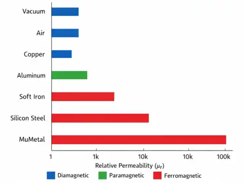
Here are some approximate relative permeability values for common materials:
| Material | Relative Permeability (μᵣ) |
|---|---|
| Vacuum | 1 |
| Air | 1.0000004 |
| Copper | 0.999991 |
| Aluminum | 1.000022 |
| Soft Iron | 5,000 |
| Silicon Steel | 7,000 |
| Mumetal | 100,000 |
| Permalloy | 80,000 |
Notice that air and vacuum have nearly identical permeability values. Diamagnetic materials like copper have relative permeability slightly less than 1. Paramagnetic materials like aluminum have values slightly greater than 1. Ferromagnetic materials have extremely high values.
3. Classification of Materials Based on Permeability
Materials can be grouped into three categories based on their magnetic behavior and permeability values.
3.1 Diamagnetic Materials
These materials have a relative permeability slightly less than 1. They weakly repel magnetic fields. Examples include copper, bismuth, silver, and gold. These materials are rarely used in magnetic circuit design because they do not support magnetic flux well.
3.2 Paramagnetic Materials
These materials have a relative permeability slightly greater than 1. They are weakly attracted to magnetic fields. Examples include aluminum, platinum, and magnesium. Their magnetic properties are too weak for most practical magnetic circuit applications.
3.3 Ferromagnetic Materials
These materials have very high relative permeability values, often in the thousands or tens of thousands. They are strongly attracted to magnetic fields and can be easily magnetized. Iron, cobalt, nickel, and their alloys fall into this category. Ferromagnetic materials are the primary choice for transformer cores, motor stators, relay armatures, and inductor cores.
The selection of core material in electrical machine design depends heavily on the permeability of available materials. Higher permeability means less magnetomotive force (MMF) is needed to establish the required flux, which translates to smaller, lighter, and more energy-efficient devices.
4. What is Reluctance?
Reluctance is the opposition offered by a magnetic circuit to the flow of magnetic flux. It is the magnetic equivalent of electrical resistance. Just as resistance opposes the flow of electric current in a conductor, reluctance opposes the establishment of magnetic flux in a magnetic path.
The symbol for reluctance is \(\mathcal{R}\) (or sometimes \(S\)). The SI unit of reluctance is Ampere-turns per Weber (AT/Wb), which is also written as \(H^{-1}\) (inverse Henry).
A magnetic circuit with high reluctance requires more magnetomotive force to establish the same amount of magnetic flux. A circuit with low reluctance allows flux to flow more easily.
The formula for reluctance is:
\(\boxed{\mathcal{R} = \dfrac{l}{(\mu \times A)}}\)
Where:
- \(\mathcal{R}\) = Reluctance (AT/Wb)
- \(l\) = Length of the magnetic path (meters)
- \(\mu\) = Absolute permeability of the material (H/m)
- \(A\) = Cross-sectional area of the magnetic path (m²)
This formula tells us three important things:
- Reluctance increases with the length of the magnetic path.
- Reluctance decreases with a larger cross-sectional area.
- Reluctance decreases with higher permeability of the core material.
5. Analogy Between Magnetic and Electric Circuits
One of the best ways to grasp reluctance and permeability is through the analogy between magnetic circuits and electric circuits. This analogy is widely used in textbook problems and practical design work.
| Electric Circuit | Magnetic Circuit |
|---|---|
| EMF (Voltage, V) | MMF (Magnetomotive Force, AT) |
| Current (I, Amperes) | Magnetic Flux (Φ, Webers) |
| Resistance (R, Ohms) | Reluctance (ℛ, AT/Wb) |
| Conductivity (σ) | Permeability (μ) |
| Ohm’s Law: V = IR | Hopkinson’s Law: MMF = Φ × ℛ |
This parallel is extremely useful. In an electric circuit, if you increase the resistance, less current flows for a given voltage. Similarly, in a magnetic circuit, if you increase the reluctance, less magnetic flux is established for a given MMF.
5.1 Hopkinson’s Law
Hopkinson’s Law (also called the Ohm’s Law of magnetic circuits) states:
\(\boxed{\text{MMF} = \Phi \times \mathcal{R}}\)
Or equivalently:
\(\boxed{\Phi = \dfrac{\text{MMF}}{\mathcal{R}}}\)
Where:
- \(\text{MMF}\) = Magnetomotive force (Ampere-turns)
- \(\Phi\) = Magnetic flux (Webers)
- \(\mathcal{R}\) = Reluctance (AT/Wb)
6. The Relationship Between Permeability and Reluctance
Permeability and reluctance are inversely related. As the permeability of a material increases, the reluctance of the magnetic path decreases. This inverse relationship is clearly visible in the reluctance formula:
\(\boxed{\mathcal{R} = \dfrac{l}{(\mu \times A)}}\)
If \(\mu\) increases and the geometry stays the same, \(\mathcal{R}\) decreases. This makes intuitive sense. A material with high permeability supports magnetic flux easily, so it offers less opposition (reluctance) to flux flow.
This is exactly why engineers choose high-permeability materials for transformer and motor cores. A lower reluctance path means the device can produce the required magnetic flux with less input current, leading to higher efficiency and lower energy losses.
Air gaps in magnetic circuits are a practical example of this relationship. Air has very low permeability (μᵣ ≈ 1), so even a small air gap introduces a large amount of reluctance into the circuit. This is why transformer cores are designed with tight joints to minimize air gaps.
7. Practical Examples
7.1 Reluctance of a Toroidal Core
Let us work through a practical calculation.
Problem: A toroidal core made of silicon steel has the following dimensions:
- Mean length of the magnetic path: \(l = 0.5 \,m\)
- Cross-sectional area: \(A = 10 \times 10^{-4} m^2\, (10 cm^2)\)
- Relative permeability of silicon steel: \(\mu_r = 5,000\)
Find the reluctance of the core.
Solution:
Step 1: Calculate absolute permeability.
\(\mu = \mu_0 \times \mu_r = (4\pi \times 10^{-7}) \times 5,000 = 6.2832 \times 10^{-3} \text{ H/m}\)
Step 2: Apply the reluctance formula.
\(\mathcal{R} = \dfrac{l}{(\mu \times A)} = \dfrac{0.5}{(6.2832 \times 10^{-3} \times 10 \times 10^{-4})}\)
\(\mathcal{R} = \dfrac{0.5}{(6.2832 \times 10^{-6})}\)
\(\mathcal{R} = 79,577 \text{ AT/Wb}\)
This is the reluctance of the silicon steel core. Now imagine replacing this core with an air core of the same dimensions. The reluctance would be 5,000 times higher because air has \(\mu_r = 1\). This example clearly shows why ferromagnetic cores are used in practical electromagnetic devices.
7.2 Effect of an Air Gap on Reluctance
Problem: The same toroidal core from Example 1 now has a 1 mm air gap cut into it. Calculate the total reluctance of the magnetic circuit.
Solution:
The magnetic circuit now has two reluctances in series: the iron core and the air gap.
Iron core reluctance (with reduced length):
\(l_{iron} = 0.5 – 0.001 = 0.499 \text{ m}\)
\(\mathcal{R}_{iron} = \dfrac{0.499}{(6.2832 \times 10^{-3} \times 10 \times 10^{-4})} = 79,418 \text{ AT/Wb}\)
Air gap reluctance:
\(l_{air} = 0.001 m \, (1 mm)\)
\(\mu_{air} = \mu_0 = 4\pi × 10^{-7} = 1.2566 \times 10{-6} \text{ H/m}\)
\(\mathcal{R}_{air} = \dfrac{0.001}{(1.2566 \times 10^{-6} \times 10 \times 10^{-4})} = 795,775 \text{ AT/Wb}\)
Total reluctance:
\(\mathcal{R}_{total} = \mathcal{R}_{iron} + \mathcal{R}_{air} = 79,418 + 795,775 = 875,193 \text{ AT/Wb}\)
Notice something remarkable here. A tiny 1 mm air gap contributes about 91% of the total reluctance of the entire magnetic circuit. The iron core, despite being 499 mm long, contributes only about 9%. This example demonstrates how powerfully air gaps affect magnetic circuit performance and why transformer cores must be assembled with minimal gaps.
8. Series and Parallel Reluctances
Magnetic circuits can be arranged in series or parallel, just like electric circuits.
8.1 Series Reluctance
If multiple reluctance elements are connected in series (the flux passes through each one sequentially), the total reluctance is the sum of individual reluctances:
\(\boxed{\mathcal{R}_{total} = \mathcal{R}_1 + \mathcal{R}_2 + \mathcal{R}_3 + …}\)
A transformer core with an air gap is a good example of series reluctance.
8.2 Parallel Reluctance
If the magnetic flux splits into two or more parallel paths, the total reluctance is calculated as:
\(\boxed{\dfrac{1}{\mathcal{R}_{total}} = \dfrac{1}{\mathcal{R}_1} + \dfrac{1}{\mathcal{R}_2} + \dfrac{1}{\mathcal{R}_3} + …}\)
The shell-type transformer core is an example where the flux divides into two parallel paths in the outer limbs.
These calculations follow the same rules as series and parallel resistances in electric circuits. This makes magnetic circuit analysis familiar and accessible to students who already know basic circuit theory.
9. Permeance: The Inverse of Reluctance
Permeance is the reciprocal of reluctance. It measures how easily a magnetic circuit allows magnetic flux to flow through it. The symbol for permeance is \(P\) (or sometimes \(\Lambda\)). The unit of permeance is Weber per Ampere-turn (Wb/AT) or simply Henry (H).
\(\boxed{P \text{ or } \Lambda = \dfrac{1}{\mathcal{R}} = \dfrac{(\mu \times A)}{l}}\)
Permeance is to reluctance what conductance is to resistance in electric circuits. A high permeance value indicates a magnetic circuit that readily supports magnetic flux. Materials with high permeability naturally have high permeance values for a given geometry.
10. Factors That Affect Permeability
Permeability is not always a fixed value. Several factors influence the permeability of a material.
10.1 Material Composition
Different materials have vastly different permeability values. Pure iron has higher permeability than cast iron. Specialized alloys like Permalloy and Mumetal are engineered to have extremely high permeability for sensitive instrumentation.
10.2 Temperature
The permeability of ferromagnetic materials changes with temperature. As temperature increases toward the Curie temperature, permeability drops sharply. Above the Curie temperature, ferromagnetic materials lose their ferromagnetic properties and behave like paramagnetic materials. For iron, the Curie temperature is about 770°C.
10.3 Magnetic Field Intensity (H)
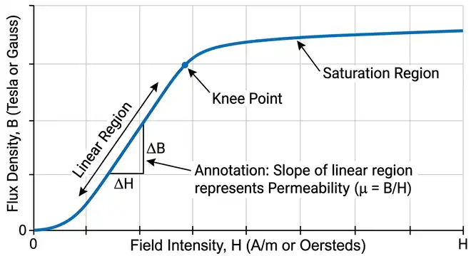
Permeability in ferromagnetic materials is not constant. It varies with the applied magnetic field intensity. At low field strengths, permeability increases. It reaches a peak value and then decreases as the material approaches magnetic saturation. This nonlinear behavior is shown in the B-H curve (magnetization curve) of the material.
10.4 Frequency
At higher frequencies, the effective permeability of a material may decrease due to eddy current losses and domain wall motion effects. This is why different core materials are used for different frequency ranges. Laminated silicon steel works well at 50/60 Hz power frequencies. Ferrite cores are preferred for high-frequency applications above 10 kHz.
10.5 Mechanical Stress
Mechanical stress and strain can alter the magnetic domain structure of a material and change its permeability. This effect is known as magnetostriction. It is an important consideration in the design of transformer cores and magnetostrictive sensors.
11. Factors That Affect Reluctance
Since reluctance depends on permeability, geometry, and path length, the following factors directly influence reluctance:
- Length of the Magnetic Path: Longer magnetic paths have higher reluctance. This is why compact core designs are preferred in transformer and motor construction.
- Cross-Sectional Area: A larger cross-sectional area provides more room for magnetic flux and reduces reluctance. However, larger cores add weight and cost.
- Core Material (Permeability): Higher permeability materials reduce reluctance. The choice of core material is one of the most impactful design decisions in electromagnetic device engineering.
- Air Gaps: Any air gap in the magnetic path adds significant reluctance. Air gaps are sometimes introduced intentionally (as in inductors to prevent core saturation) and sometimes exist due to manufacturing tolerances (as in motor air gaps between stator and rotor).
- Temperature: Because permeability changes with temperature, reluctance also changes with temperature.
12. The B-H Curve and Its Relation to Permeability
The B-H curve (also called the magnetization curve or hysteresis loop) is a graph that shows the relationship between magnetic flux density (B) and magnetic field intensity (H) for a material.
The slope of the B-H curve at any point gives the permeability at that operating point:
\(\boxed{\mu = \dfrac{B}{H}}\)
At low values of H, the B-H curve rises steeply, indicating high permeability. As H increases further, the curve flattens out. This flattening is called magnetic saturation. At saturation, increasing H produces very little additional B, and the effective permeability drops toward the permeability of free space.
The shape of the B-H curve varies between materials. Soft magnetic materials (like silicon steel) have narrow hysteresis loops and are easy to magnetize and demagnetize. Hard magnetic materials (like alnico and neodymium) have wide hysteresis loops and retain their magnetism. Permeability behavior differs accordingly.
13. Applications of Permeability and Reluctance in Engineering
13.1 Transformer Design
Transformers use high-permeability silicon steel cores to minimize reluctance and reduce the magnetizing current needed to establish flux. Laminated cores reduce eddy current losses at power frequencies. Proper core material selection based on permeability data is a fundamental step in transformer engineering.
13.2 Electric Motor Design
In motors, the air gap between the stator and rotor is a major source of reluctance. Motor designers keep this air gap as small as mechanically possible to reduce the total reluctance and improve motor efficiency. The permeability of the stator and rotor iron also affects overall motor performance.
13.3 Inductor and Choke Design
Inductors often include a deliberate air gap in the core. This air gap increases reluctance and prevents the core from saturating at high currents. The inductance value is directly related to the number of turns and the reluctance of the magnetic circuit:
\(L = \dfrac{N^2}{\mathcal{R}}\)
This formula shows that inductance increases with more turns and decreases with higher reluctance.
13.4 Relay and Solenoid Design
Relays and solenoids depend on magnetic force to actuate mechanical contacts or plungers. The permeability of the core material and the reluctance of the magnetic path determine how much force the device can produce for a given coil current.
13.5 Magnetic Shielding
High-permeability materials like Mumetal are used to create magnetic shields that redirect stray magnetic fields away from sensitive electronic equipment. The shield provides a low-reluctance path that diverts the flux.
13.6 Magnetic Sensors
Sensors that measure magnetic fields often rely on materials with specific permeability characteristics. Fluxgate magnetometers and Hall effect sensors are examples where permeability plays a role in sensor design and calibration.
14. ANSI and IEEE Standards Related to Magnetic Materials
Several industry standards govern the testing, classification, and application of magnetic materials. Here are some relevant standards:
- ANSI/IEEE C57.12.00 – General requirements for liquid-immersed distribution, power, and regulating transformers. This standard includes specifications related to core materials and their magnetic properties.
- ANSI/IEEE C57.12.90 – Test code for liquid-immersed transformers. It covers methods for measuring core loss, exciting current, and other parameters affected by permeability.
- ASTM A340 – Standard terminology of symbols and definitions relating to magnetic testing. This standard defines permeability, reluctance, and related magnetic quantities.
- ASTM A343/A343M – Standard test method for alternating-current magnetic properties of materials using the Epstein frame. This method is used to measure the permeability and core loss of electrical steel samples.
- IEC 60404 – Magnetic materials series of standards. These international standards cover the classification, testing, and specification of soft and hard magnetic materials used in electrical engineering.
15. Summary Table: Permeability vs. Reluctance
| Property | Permeability (μ) | Reluctance (ℛ) |
|---|---|---|
| Definition | Measure of how easily a material supports magnetic flux | Measure of opposition to magnetic flux flow |
| Symbol | μ | ℛ (or S) |
| SI Unit | H/m (Henry per meter) | AT/Wb (Ampere-turns per Weber) |
| Formula | μ = μ₀ × μᵣ | ℛ = l / (μ × A) |
| Electric Analogy | Conductivity (σ) | Resistance (R) |
| Effect of High Value | More flux for given MMF | Less flux for given MMF |
| Relationship | Inversely proportional to reluctance | Inversely proportional to permeability |
16. Conclusion
Permeability and reluctance are two interconnected concepts that form the basis of magnetic circuit analysis. Permeability describes a material’s ability to conduct magnetic flux. Reluctance describes how much a magnetic circuit resists the flow of that flux. Together, they allow engineers to calculate magnetic flux, select appropriate core materials, and optimize the design of transformers, motors, inductors, relays, and many other electromagnetic devices.
A solid grasp of these concepts helps students solve magnetic circuit problems with confidence and prepares them for advanced topics in electrical machine design and power engineering.
17. Frequently Asked Questions (FAQs)
Permeability measures how easily a material allows magnetic flux to pass through it. Reluctance measures the opposition a magnetic circuit offers to the flow of magnetic flux. They are inversely related. Higher permeability means lower reluctance for the same geometry.
The SI unit of reluctance is Ampere-turns per Weber (AT/Wb), which is also equivalent to inverse Henry (H⁻¹).
Air has a relative permeability of approximately 1, which is thousands of times lower than ferromagnetic materials. Even a small air gap introduces a large reluctance because μ appears in the denominator of the reluctance formula.
The permeability of free space (μ₀) is a physical constant equal to 4π × 10⁻⁷ H/m, approximately 1.2566 × 10⁻⁶ H/m.
No. Every material and every magnetic path has some reluctance. Even superconducting materials and high-permeability alloys have a small but nonzero reluctance.
Hopkinson’s Law is the magnetic circuit equivalent of Ohm’s Law. It states that MMF = Φ × ℛ, where MMF is the magnetomotive force, Φ is the magnetic flux, and ℛ is the reluctance.
The permeability of ferromagnetic materials decreases as temperature rises. Above the Curie temperature, ferromagnetic materials lose their high permeability and behave like paramagnetic materials.
Specialized alloys like Mumetal (μᵣ ≈ 100,000) and Permalloy (μᵣ ≈ 80,000) have the highest permeability values. These materials are used in magnetic shielding and sensitive instrumentation.
Permeance is the reciprocal of reluctance. It measures how easily a magnetic circuit allows flux to flow. Its unit is Weber per Ampere-turn (Wb/AT) or Henry (H).