A Star Delta Starter sometimes also called a Wye-Delta Starter is a type of circuit that is used to run large rating 3-phase induction motors generally more than 75kW.
In our plant, we have Star Delta Starters for motors of rating 90kW and 110kW. These motors run on a 440V power supply.
The star delta starter circuit is designed in such a way that the motor first runs in star configuration during starting and when the motor achieves the speed of approx. 80% of the full load speed then the motor circuit is converted to Delta configuration automatically.
Why Star Delta Starter is Used?
An Induction motor draws a very high current during starting. This high current is also called in-rush current.
The reason for this in-rush current is that the rotor is at a standstill condition before starting and there is no counter electromotive force or back emf present to limit the current.
This inrush current if not limited may lead to electrical stress in the motor as well as in the electrical system. This further may result in breakdown and burning of the motor.
Therefore a star-delta starter is used to run large-rating induction motors where the starting current is very high.
The star configuration reduces the in-rush current up to 30% of the full load current by reducing the voltage during starting.
Then, after a certain period say 5 seconds (this time may be different for different motors) the motor automatically runs in Delta configuration.
A Practical Star Delta Starter
We are already aware of the circuit diagram (both power and control) of a Star Delta Starter. But very less of us have seen what the Star Delta starter looks like in real.
Therefore I thought of sharing one photograph of a practical star delta starter.
Let’s have a look.
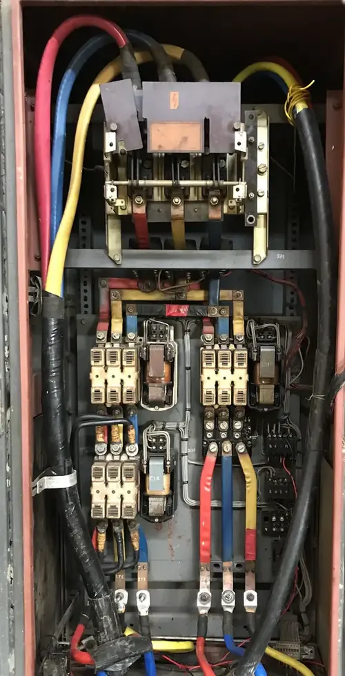
The various parts of a Star Delta Starter are described below:
#1 Isolator
Isolator is the first and one of the most important components of a Star Delta starter.
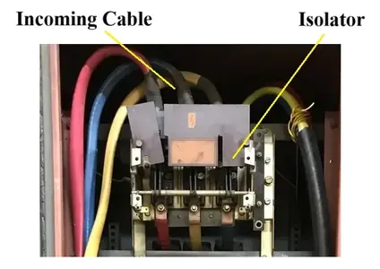
An isolator is used to isolate the starter from the main power supply or incoming power supply. The incoming cable from the power source connects to this isolator.
Some isolators use fuses to protect the circuit from any faults.
During maintenance of the starter, the isolator is kept in the OFF position.
#2 Contactors
Another important element of a star delta starter is a contactor.
A contactor is a switching device that can be controlled through a low-voltage control circuit. ON and OFF push buttons are used to control it. The contractor is responsible for running or stopping the motor.
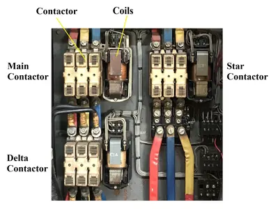
There are three contactors of the same rating used in a Star Delta Starter. One is called the main contactor, one is for Star Configuration and the other is for Delta Configuration.
During the starting of the motor, the Main Contactor and the Star Contactor are closed which runs the motor. After a certain period, the star contactor opens automatically and the Delta Contactor closes. Now, the motor runs with these Main and Delta Contactors.
#3 Thermal Overload Relay
The Thermal Overload Relay is the only protective device that is used in a Star Delta Starter for protecting the motor from excessive current.
A Thermal Overload Relay is an electromechanical device that is connected in series with the motor. Hence, the same amount of current flows through both the overload relay and the motor winding.
Therefore, if the motor is drawing excessive current than the setting in the thermal overload relay, the overload relay trips and protects the motor from burning and winding damage.
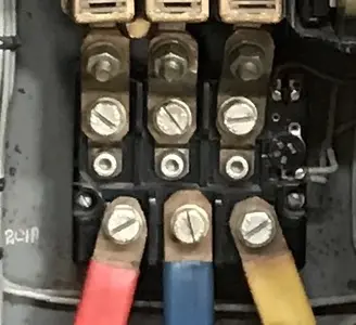
For the starter in the above photograph I have shared, the full load current of the induction motor is 151 Amp. Therefore, I have kept the thermal overload setting at approximately 150 A. Now, if the motor is drawing 170 Amp for say 10 mins, the overload relay will trip and turn the motor OFF.
This tripping time will be reducing if the current drawn is increasing and vice versa.
#4 Control Circuit
The control circuit in a Star-Delta Starter is responsible for powering ON and OFF the contactors.
The control circuit contains Control Fuses, NO/NC Contacts, Contactor Coils, ON & OFF Push Buttons, and a Timer.
The ON and OFF push buttons are generally placed at the field side near the Motor.
#5 Measuring Circuit
The measuring circuit is responsible for the measurement of currents drawn by the motor and the voltages across the motor.
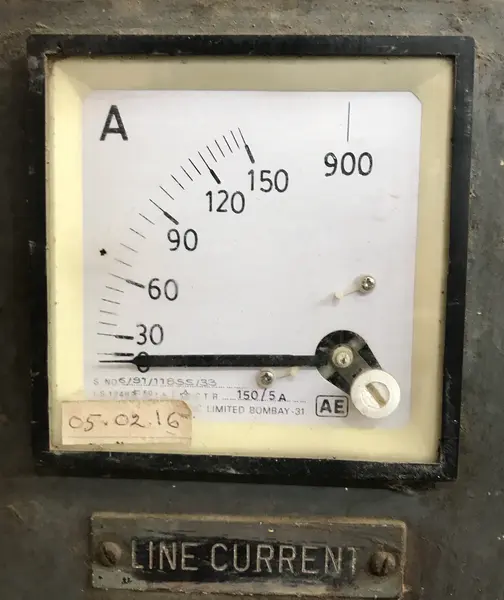
Current Tranformers along with an Ammeter are used for the measurement of Current and a Voltmeter is used for the measurement of Voltages.
This helps in monitoring the motor current from time to time.
Connection at Motor Terminal Block
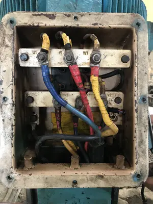
In Star Delta Starter, two runs of outgoing cables are used from the Starter to the Motor Terminal Block. One cable comes from the Star Contactor and the other one comes from Delta Connector.
The Bottom Line
I hope this article about the Practical Star Delta Starter and Its components has helped you to learn more about it and visualize what a Star Delta starter looks like.
If you have any queries or comments, feel free to tell us in the comment section below.
I would love to hear from you.