Protection relays are the guardians of every electrical power system. They detect abnormal conditions such as overcurrent, earth faults, and differential faults. They then issue trip commands to circuit breakers within milliseconds. To confirm that these relays operate correctly before they are put into service, engineers perform secondary injection testing. This test method allows technicians to simulate fault conditions directly at the relay terminals without energizing the primary power system.
Secondary injection testing is one of the most widely practiced relay testing techniques across utilities, industrial facilities, and commissioning projects. It is used during factory acceptance tests, site commissioning, periodic maintenance, and after any relay replacement or firmware upgrade. The test verifies pickup values, timing characteristics, and trip logic of the relay independently.
In this technical guide, we will discuss everything you need to know about secondary injection testing for relays, including its working principle, required equipment, step-by-step procedures, ANSI relay codes, safety precautions, common mistakes, interpretation of results, and relevant industry standards. Practical examples are included throughout to help you apply these concepts in real-world scenarios confidently.
1. What is Secondary Injection Testing?
Secondary injection testing is a method of testing protection relays by injecting current or voltage signals directly into the relay’s secondary terminals. The injected signals simulate the output of current transformers (CTs) and voltage transformers (VTs) during fault conditions. This approach bypasses the primary power circuit entirely.
The purpose is to verify that the relay responds to different fault magnitudes and types according to its programmed settings.
For example, if an overcurrent relay is set to pick up at 5 amperes, the test will confirm that the relay actually operates at or very near 5 amperes. The test also checks the time delay associated with each protection element.
This method differs from primary injection testing, where actual high current is passed through the primary winding of the CT and the entire measurement chain is tested. Secondary injection focuses only on the relay itself and the wiring from the relay to the trip circuit.
2. Why Secondary Injection Testing Is Necessary
Protection relays must operate with precision during fault events. A relay that fails to trip during a genuine fault can cause equipment damage, fire hazards, and even endanger human life. A relay that trips unnecessarily causes nuisance outages and production losses.
Secondary injection testing confirms the following:
- The relay picks up at the correct current or voltage setting.
- The relay operates within the specified time delay.
- The trip contact closes and sends the trip signal to the circuit breaker.
- The alarm contacts function properly.
- The relay resets after the fault condition is cleared.
- The directional elements respond to the correct phase angle.
- The relay logic operates as per the protection scheme design.
Regular testing through secondary injection is a standard requirement in most national and international electrical standards. Power utilities and large industrial plants schedule these tests during planned shutdowns periodically.
3. Equipment Required for Secondary Injection Testing
To perform secondary injection testing, you need specialized test equipment. The most common device used is a relay test set (also called a relay test kit or secondary injection kit). Several manufacturers produce these kits, including Omicron, Megger, Doble, ISA, and Ponovo.
3.1 A standard relay test set includes the following
- Current source – Capable of generating adjustable AC current from milliamperes to tens of amperes. Most test sets provide three-phase current outputs for testing multi-phase relays.
- Voltage source – Adjustable AC voltage output for testing voltage-dependent relay elements such as undervoltage (ANSI 27) and overvoltage (ANSI 59) relays.
- Timer – A built-in precision timer that measures the relay’s operating time from the moment of injection to the moment the relay contact changes state.
- Binary inputs – Used to detect the state change of the relay’s output contacts (trip, alarm, close commands).
- Phase angle control – Allows the operator to set the phase angle between injected current and voltage. This is necessary for testing directional relays (ANSI 67) and power relays (ANSI 32).
- Software interface – Modern relay test sets come with software that automates test sequences, generates test reports, and stores results for future reference.
3.2 Additional tools required:
- Multimeter for continuity checks
- Relay setting sheets and protection coordination study documents
- Wiring diagrams and schematic drawings
- Insulated test leads and crocodile clips
- Personal protective equipment (PPE)
- Laptop with test set software installed
4. ANSI Relay Codes Relevant to Secondary Injection Testing
Each protection function in a relay is identified by an ANSI/IEEE device number. During secondary injection testing, you will test specific ANSI functions depending on the relay type. Here is a list of commonly tested ANSI codes:
| ANSI Code | Protection Function |
|---|---|
| 21 | Distance Protection |
| 25 | Synchrocheck |
| 27 | Undervoltage Protection |
| 32 | Directional Power |
| 46 | Negative Sequence Overcurrent |
| 49 | Thermal Overload |
| 50 | Instantaneous Overcurrent |
| 51 | Time Overcurrent |
| 50N/51N | Earth Fault (Ground Overcurrent) |
| 59 | Overvoltage Protection |
| 67 | Directional Overcurrent |
| 79 | Auto-Reclosing |
| 81 | Frequency Protection |
| 87 | Differential Protection |
Each of these functions has its own pickup value, time delay curve, and operating logic. The secondary injection test must verify each enabled function individually.
5. Step-by-Step Procedure: How to Perform a Secondary Injection Test
5.1 Step 1: Review the Relay Settings and Protection Scheme
Before touching any equipment, study the relay settings thoroughly. Obtain the protection coordination study report and the relay setting file. Identify each protection element that is enabled, along with its pickup value, time multiplier setting (TMS), curve type, and time delay.
Also review the single line diagram (SLD), AC schematic, DC schematic, and wiring diagrams. Understand how the relay connects to the CT secondaries, VT secondaries, trip circuit, and alarm circuit.
Example: An overcurrent relay (ANSI 50/51) might have the following settings:
- Phase overcurrent pickup (51): 1.2 × In (where In = 1A or 5A secondary)
- Time dial/TMS: 0.3
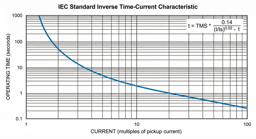
- Curve type: IEC Standard Inverse (SI)
- Instantaneous overcurrent pickup (50): 10 × In
- Instantaneous time delay: 0 ms (or a fixed definite time of 50 ms)
5.2 Step 2: Isolate the Relay and Take Safety Precautions
Safety is the top priority. Follow your organization’s lockout/tagout (LOTO) procedures. De-energize the circuit and confirm isolation using a voltage tester.
Disconnect the relay’s CT inputs from the actual current transformers. Short-circuit the CT secondary terminals at the CT terminal block before disconnecting the wiring. This prevents dangerous open-circuit voltages from appearing across the CT secondary if the primary is energized accidentally.
Disconnect the trip circuit from the circuit breaker if you do not want the breaker to trip during testing. In many cases, the breaker is already racked out during commissioning.
Inform the control room and all relevant personnel about the testing activity.
5.3 Step 3: Connect the Relay Test Set to the Relay
Connect the current output of the test set to the relay’s current input terminals. Match each phase correctly, connect the test set’s Phase A output to the relay’s Phase A current input, and so on.
Connect the voltage output if the relay has voltage-dependent protection elements. Again, match phase connections accurately.
Connect the binary input of the test set to the relay’s trip contact output. This allows the test set timer to detect when the relay issues a trip command.
Double-check all connections against the wiring diagram. A wrong connection can produce incorrect test results or damage the test equipment.
5.4 Step 4: Power Up the Relay
Apply the auxiliary power supply to the relay. Most modern numerical relays require a DC auxiliary supply (typically 110V DC or 220V DC). Some relays accept AC auxiliary supply. Confirm that the relay powers up and initializes without errors.
Check the relay’s front panel or HMI to confirm its settings match the setting sheet. If there is any mismatch, resolve it before proceeding with testing.
5.5 Step 5: Perform Pickup Test
The pickup test verifies the minimum current (or voltage) at which the relay starts to operate. Increase the injected current gradually from zero until the relay picks up.
Procedure for overcurrent pickup (ANSI 51):
- Set the test set to ramp mode or manual increment mode.
- Start injecting current from a value well below the pickup setting.
- Increase the current slowly in small steps (e.g., 0.01A increments for a 1A CT secondary relay).
- Observe the relay’s front panel LEDs or the test set’s binary input channel.
- Record the current at which the relay indicates a pickup condition.
- Compare the recorded pickup value with the expected setting.
Acceptable tolerance: Most relay manufacturers specify a pickup accuracy of ±3% to ±5%. For example, if the pickup setting is 6.0A, the relay should pick up between 5.70A and 6.30A (for ±5% tolerance).
5.6 Step 6: Perform Timing Test
The timing test verifies that the relay trips within the correct time for a given fault current magnitude. This test is performed at multiple points on the relay’s time-current characteristic curve.
Procedure for time overcurrent (ANSI 51) timing test:
- Set the test set to inject a specific multiple of the pickup current (e.g., 2×, 5×, 10× pickup).
- Apply the current instantaneously (step injection).
- The test set timer starts at the moment of injection.
- The timer stops when the relay trip contact changes state.
- Record the measured operating time.
- Compare the measured time against the calculated expected time using the relay’s curve equation.
Example: For an IEC Standard Inverse curve, the operating time formula is:
\(t = \dfrac{\text{TMS} \times 0.14 }{\left(\frac{I}{I_s}\right)^{0.02} – 1}\)
Where:
- \(t\) = operating time in seconds
- \(\text{TMS}\) = time multiplier setting
- \(I\) = fault current
- \(I_s\) = pickup current setting
If TMS = 0.3, Is = 6A, and I = 30A (5× pickup):
\(t = \dfrac{0.3 \times 0.14}{\left(\frac{30}{6}\right)^{0.02} – 1}\)
\(t = \dfrac{0.3 \times 0.14}{5^{0.02} – 1}\)
\(t = \dfrac{0.042}{1.0327 – 1}\)
\(t = \dfrac{0.042}{0.0327}\)
\(t ≈ 1.284 \text{seconds}\)
The measured trip time should be close to 1.284 seconds with an acceptable tolerance of ±5% or ±50ms, depending on the relay manufacturer’s specification.
5.7 Step 7: Perform Instantaneous Overcurrent Test (ANSI 50)
For the instantaneous element, inject the current at the instantaneous pickup setting and verify that the relay trips within the specified definite time (usually less than 60ms for numerical relays).
Gradually increase the current to find the exact instantaneous pickup point. Then perform a timing test at 1.1× and 1.5× the instantaneous pickup setting.
5.8 Step 8: Test Earth Fault Elements (ANSI 50N/51N)
If the relay has earth fault protection, inject current into the residual (neutral) current input of the relay. Follow the same pickup and timing procedures as described above.
Some relays derive the residual current internally by vector summation of the three phase currents. In this case, inject current through only one phase and leave the other two phases at zero. The relay will interpret this unbalanced condition as an earth fault.
5.9 Step 9: Test Directional Elements (ANSI 67)
For directional overcurrent relays, you must inject both current and voltage simultaneously. The relay determines the fault direction based on the phase angle relationship between the current and the reference voltage.
Set the test set to inject the current at the correct phase angle with respect to the voltage. Test the relay for both forward and reverse fault directions. The relay should pick up only for the intended direction.
5.10 Step 10: Test Voltage Protection Elements (ANSI 27, 59, 81)
For undervoltage (27) testing, apply rated voltage and then reduce it gradually until the relay picks up. Record the pickup voltage and time delay.
For overvoltage (59) testing, apply rated voltage and increase it gradually until the relay operates.
For frequency protection (81), inject voltage at the rated magnitude and vary the frequency to find the pickup point for underfrequency (81U) and overfrequency (81O) functions.
5.11 Step 11: Test Trip Circuit and Alarm Contacts
Verify that the trip contact output of the relay actually energizes the trip coil circuit of the circuit breaker. Check continuity of the trip circuit wiring. If the circuit breaker is available, perform an end-to-end trip test by allowing the relay to trip the breaker during the secondary injection test.
Also verify that the alarm contacts (normally open or normally closed) change state correctly when the relay operates.
5.12 Step 12: Record Results and Generate Test Report
Document all test results in a structured format. Include the following information:
- Relay make, model, and serial number
- CT and VT ratios
- Each ANSI element tested
- Setting values for pickup, TMS, curve type, and time delay
- Measured pickup values and operating times
- Pass/fail status for each test point
- Tester’s name and date of testing
- Any deviations or observations
Most modern test sets can generate automated reports through their software. Store these reports for future reference and regulatory compliance.
6. Interpreting Secondary Injection Test Results
After completing all tests, compare the measured values with the expected values. Minor deviations are normal. Here are some guidelines for interpretation:
Pickup accuracy: A deviation within ±3% for numerical relays and ±5% for electromechanical relays is acceptable generally.
Timing accuracy: A deviation within ±5% or ±50ms (whichever is greater) is acceptable for most numerical relays. Electromechanical relays may have wider tolerances up to ±10%.
If the relay fails a test point:
- Re-check the relay settings in the relay’s configuration.
- Verify that the correct CT ratio and curve type are selected in both the relay and the test set software.
- Inspect the relay for hardware faults.
- Re-test after correcting any identified issues.
- If the relay consistently fails, contact the manufacturer for technical support.
7. Common Mistakes During Secondary Injection Testing
Several errors can lead to incorrect test results. Avoid these common pitfalls:
- Not shorting CT secondaries before disconnecting wires – This is a safety hazard and can damage the CT insulation.
- Wrong phase connections – Swapping phases will produce incorrect directional and differential test results.
- Incorrect CT ratio in test set software – The test set needs to know the CT ratio to display primary values correctly.
- Testing with the trip circuit still connected to a live breaker – This may cause unintended breaker operations during testing.
- Not accounting for the relay’s reset time – Some relays take a few seconds to reset after a trip. Injecting the next test too quickly can produce inaccurate timing results.
- Using the wrong curve type in calculations – IEC and IEEE/ANSI curves have different equations. Make sure you use the same curve that is programmed in the relay.
8. Secondary Injection Testing for Differential Relays (ANSI 87)
Differential protection relays require a more complex test setup. These relays compare current entering and leaving a protected zone (transformer, generator, busbar, or motor). The relay operates when the differential current exceeds a set threshold.
For testing transformer differential relays (ANSI 87T), you must inject currents into both the HV and LV side CT inputs of the relay simultaneously. The test set must simulate the CT ratio compensation and phase shift that the relay is configured to handle.
Test points for differential relays:
- Stability test (through-fault test): Inject balanced currents into both sides. The relay should remain stable and not trip.
- Pickup test: Inject differential current (current into one side only) and find the pickup point.
- Slope characteristic test: Inject currents at various bias levels and differential levels to trace the relay’s percentage bias characteristic curve.
- High-set differential test: Inject a large differential current to verify the instantaneous high-set element operates quickly.
Modern relay test sets have dedicated differential relay test modules that automate these complex test scenarios effectively.
9. Frequency of Secondary Injection Testing
The frequency of testing depends on the type of installation, the age of the relay, and the applicable regulatory standards.
- During commissioning: Every new relay must be tested before energization.
- After relay replacement or firmware upgrade: Re-test all protection functions.
- Periodic maintenance: Every 3 to 6 years for numerical relays. Electromechanical relays may require testing every 1 to 3 years due to mechanical wear.
- After a protection mal-operation or failure to trip: Test the relay to identify the root cause.
- After CT or VT replacement: Verify the relay still operates with the new transformer ratios.
10. Relevant Industry Standards for Relay Testing
Several international standards provide guidelines for protection relay testing:
| Standard | Description |
|---|---|
| IEEE C37.103 | Guide for Differential and Polarizing Relay Circuit Testing |
| IEEE C37.90 | Standard for Relays and Relay Systems Associated with Electric Power Apparatus |
| IEC 60255 | Measuring Relays and Protection Equipment |
| IEC 61850 | Communication Networks and Systems for Power Utility Automation |
| NERC PRC-005 | Protection System Maintenance (North America) |
| NETA MTS | Maintenance Testing Specifications (NETA) |
These standards define testing procedures, acceptable tolerances, test intervals, and documentation requirements. Following these standards helps maintain compliance and improves power system reliability.
11. Secondary Injection vs. Primary Injection
| Parameter | Secondary Injection | Primary Injection |
|---|---|---|
| Test point | Relay terminals | CT primary winding |
| Current magnitude | Low (1A–100A) | High (100A–10,000A+) |
| Equipment size | Compact and portable | Large and heavy |
| Tests CT accuracy | No | Yes |
| Tests relay function | Yes | Yes |
| Tests wiring from CT to relay | No | Yes |
| Commonly used for | Relay commissioning, maintenance | CT ratio verification, end-to-end testing |
In practice, both tests complement each other. Secondary injection is performed first to verify the relay. Primary injection is then performed to verify the entire measurement chain from CT to relay.
12. Conclusion
Secondary injection testing is a fundamental procedure in power system protection engineering. It verifies that each relay operates at the correct pickup values and within the specified time delays. The test requires a systematic approach, starting from a thorough review of relay settings and ending with detailed documentation of results.
Every electrical engineer and protection technician should master this testing technique. Performing secondary injection tests correctly prevents relay misoperations, reduces equipment damage, and enhances the safety of the entire power system. The test procedure may vary slightly depending on the relay type and manufacturer, but the core principles remain the same.
13. Frequently Asked Questions (FAQs)
Primary injection involves passing a high current through the CT primary winding to test the entire chain from CT to relay. Secondary injection involves injecting a low current directly into the relay’s secondary terminals, testing only the relay and its wiring to the trip circuit.
A relay test set (secondary injection kit) is the primary equipment needed. It provides adjustable current and voltage outputs, a precision timer, binary inputs, and phase angle control. A multimeter, test leads, and a laptop with test software are also required.
Numerical relays should be tested every 3 to 6 years during periodic maintenance. Electromechanical relays may require testing every 1 to 3 years. Testing is also required during commissioning, after relay replacement, and after any protection event.
Most numerical relays have a pickup accuracy tolerance of ±3%. Electromechanical relays may have tolerances up to ±5% or wider.
No. The relay must be isolated from the live power system before testing. CT secondary circuits must be shorted before disconnecting wires.
If the relay fails, re-verify the settings, check wiring connections, and re-test. If the relay continues to fail, inspect it for hardware faults and contact the manufacturer. Do not put a failed relay into service.
Yes. Modern relay test sets can inject three-phase currents and voltages simultaneously with precise phase angle and magnitude control. This allows simulation of faults at different impedance zones for distance relay testing.
Yes. Disconnect the CT secondary wires at the relay terminal and short-circuit the CT secondary at the CT terminal block. Then connect the test set to the relay terminals directly.
Yes. The procedure applies to both relay types. However, electromechanical relays may require higher injection currents and have wider operating tolerances compared to numerical relays.