Transformers are the backbone of electrical power distribution systems. Inside every power transformer, insulating oil plays a critical role—it cools the windings, provides electrical insulation, and protects internal components from damage. However, transformers constantly “breathe” as operating conditions change. Every time your transformer experiences load variations or temperature fluctuations, the insulating oil expands and contracts, forcing air in and out of the conservator tank.
This continuous breathing creates a serious problem: moisture from ambient air can enter the transformer. If moisture mixes with transformer oil, it degrades the dielectric strength of the insulation, potentially causing equipment failure, short circuits, and costly downtime. This is where silica gel breathers become essential.
A silica gel breather is a simple yet critical device that removes moisture from incoming air before it enters the transformer. It ensures that only dry air enters the system during the breathing cycle.
The Transformer Breathing Cycle
When your transformer operates under load, the current flowing through the windings generates heat. This heat transfers to the insulating oil, causing it to expand. As the oil expands, it occupies more volume in the conservator tank. This expansion forces existing air out of the system through the breather.
Conversely, when the load decreases or the transformer cools down overnight, the oil contracts and its volume decreases. This creates a partial vacuum in the conservator, which draws fresh air back into the system. However, this incoming air from the atmosphere typically contains moisture and dust particles, without protection, this moist air mixes directly with the transformer oil, causing:
- Reduced dielectric strength – Making the oil less effective at insulation
- Condensation formation – Water droplets accumulating on windings
- Corrosion – Internal metallic components rust when exposed to moisture
- Accelerated aging – Insulation paper degrades faster
- Reduced equipment lifespan – Transformer may fail prematurely
The silica gel breather prevents all these problems by filtering and drying the incoming air.
How Does a Silica Gel Breather Work?
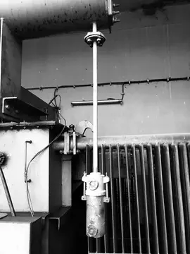
A silica gel breather is a transparent cylindrical container made of plastic or metal, typically 4-6 inches in diameter and 12-18 inches tall. Inside this container are three main components:
1. Silica Gel Crystal Beads – The primary desiccant material that absorbs moisture. These are chemically pure silicon dioxide crystals with a high surface area for moisture absorption. A single 5 kg batch of silica gel can absorb approximately 1 kg of water (about 20% of its weight) before becoming saturated.
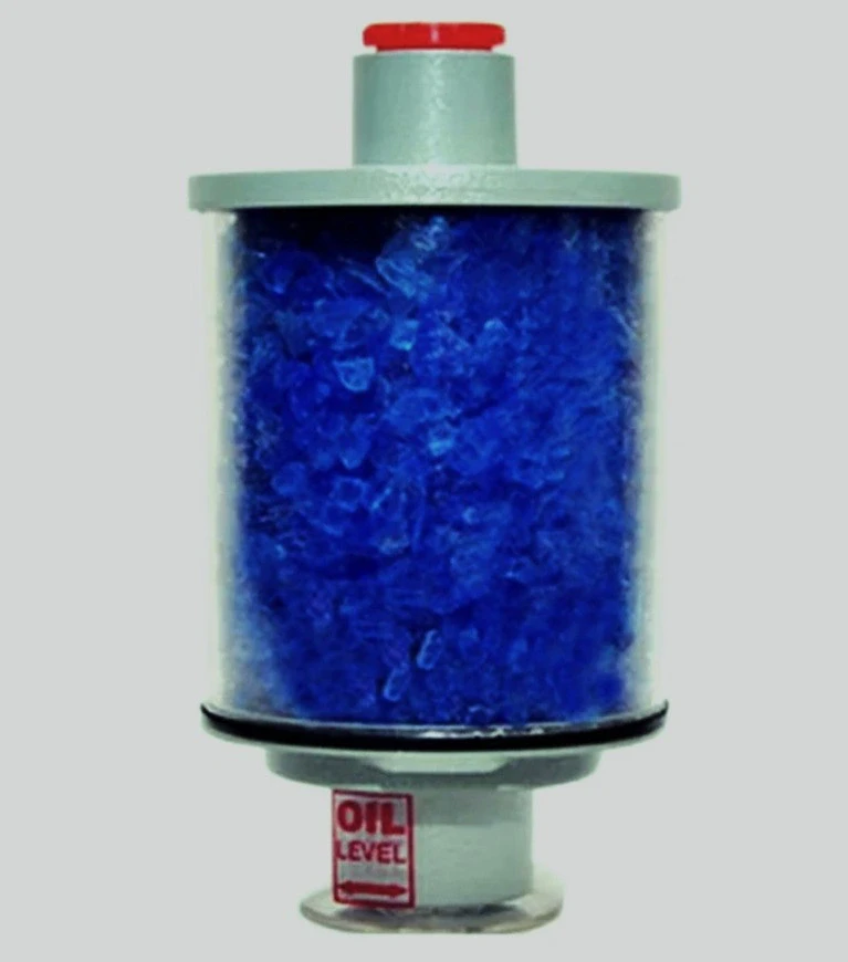
2. Oil Trap (Oil Cup) – A small chamber located below the silica gel that collects oil mist and dust particles. This prevents contaminants from reaching the silica gel and allows you to visually inspect for accumulated dust and oil degradation.
3. Breathing Holes – Multiple small ports where air enters and exits the breather during the transformer’s breathing cycle.
How Silica Gel Removes Moisture from Humid Air?
Step 1: Air Intake – When the transformer cools and oil contracts, a negative pressure develops. This vacuum sucks humid air from the atmosphere into the breather through the breathing holes.
Step 2: Oil Trap Filtration – Before reaching the silica gel, the air passes through the oil cup where dust particles and oil mist are trapped and settle.
Step 3: Silica Gel Adsorption – As the air passes through the silica gel crystals, moisture molecules are attracted to and absorbed into the porous surface of the crystals. The moisture remains locked in the crystal pores, preventing it from entering the transformer oil.
Step 4: Dry Air Release – Completely dry air emerges from the other side of the breather and enters the transformer conservator tank.
Silica gel can remove practically all moisture from incoming air—typically achieving 99%+ moisture removal efficiency. This keeps your transformer oil at the optimal moisture level required for peak performance.
The Color Indicator
One of the best features of quality silica gel breathers is the color-indicating silica gel. This crystal-doped indicator changes color as it absorbs moisture, giving technicians an instant visual signal of saturation levels without any equipment or testing.
Different manufacturers use different color systems, but the most common ones are:
Blue/Orange Color System (Most Common)
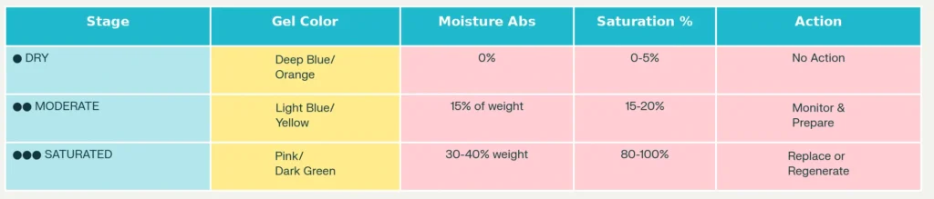
- Deep Blue or Orange = Completely dry silica gel (0-5% saturation)
- Light Blue or Yellow = Partially saturated (15-20% saturation) – Absorbed about 15% of its weight in moisture
- Pink or Dark Green = Fully saturated (80-100% saturation) – Absorbed 30-40% of its weight in moisture
What Each Color Means?
When You See Deep Blue/Orange Color:
Your breather is in perfect condition. The transformer is receiving maximum protection from moisture. Continue normal monitoring.

When You See Light Blue/Yellow Color:
The silica gel has absorbed some moisture but still has significant capacity remaining. You should prepare for regeneration in the near future. Many facilities schedule regeneration at this stage to avoid reaching full saturation.
When You See Pink/Dark Green Color:
This is urgent! Your silica gel is fully saturated and can no longer absorb additional moisture. Replace or regenerate the silica gel immediately. Operating with saturated silica gel is like having no breather protection at all and moisture will freely enter your transformer.

💡 DID YOU KNOW?
A single breather with saturated silica gel can allow MORE moisture to enter your transformer than if there were NO breather at all!
How to Regenerate Saturated Silica Gel
If you’re using a breather with regenerable silica gel, you can dry it out and reuse it multiple times. However, many modern breathers use disposable silica gel cartridges for convenience.
To regenerate silica gel:
- Remove the breather from the conservator (the transformer can be online or offline for this procedure)
- Heat the silica gel in a standard kitchen or laboratory oven at 150°C (302°F) for 2-4 hours
- Watch for color change – The silica gel will gradually return from pink to blue as moisture evaporates
- Allow cooling – Let the breather cool completely to room temperature before reinstalling
- Reinstall on the conservator
Important: Never expose silica gel to temperatures above 200°C, as this can damage the crystal structure. Also, never pour water directly on silica gel to clean it and allow it to air dry completely.
Power Transformer Silica Gel Breather Specifications
What is Air Cell or Conservator Bladder?
Modern large transformers (typically above 5 MVA capacity) use a component called an air cell or conservator bladder.
An air cell is a flexible membrane made of nylon fabric coated with NBR (Nitrile Rubber) or other elastomers. It’s sealed inside the conservator tank and acts as a non-porous barrier between transformer oil and the atmosphere. Think of it as a balloon inside the conservator that inflates and deflates with oil level changes.
How the Air Cell Works
During Oil Expansion (Heating):
- Oil heats up and expands
- The expanding oil pushes against the air cell, compressing the air inside it
- The compressed air inside the cell is forced out through the breather pipe
- The air cell becomes smaller and more compressed
During Oil Contraction (Cooling):
- Oil cools down and contracts
- The external pressure (from atmospheric air drawn through the breather) pushes on the outside of the air cell
- The air cell expands, drawing air through the breather
- The air cell becomes larger and more inflated
Why Use an Air Cell?
The air cell provides several critical advantages:
1. Eliminates Direct Air-Oil Contact – Without an air cell, atmospheric air would directly contact the transformer oil in the conservator. The air cell completely separates the oil from the atmosphere, preventing oxidation and moisture absorption even if the silica gel breather malfunctions or becomes saturated.
2. Reduces Oxygen Contamination – Only a small portion of oil is exchanged between the main tank and conservator. With an air cell, this oil exchange is minimized further, keeping oxygen levels low.
3. Maintains Oil Purity – Since the air is isolated in the air cell, even if the silica gel becomes saturated momentarily, the oil remains protected.
4. Provides Backup Protection – If a technician forgets to replace the silica gel, the air cell continues providing some protection until the gel can be changed.
5. Prevents Bubble Formation – The air cell maintains consistent pressure on the oil surface, preventing the oil from becoming supersaturated with gases and forming bubbles that reduce dielectric strength.
Air Cell Components and Specifications
The air cell has a mounting flange that connects to the top of the conservator. A breather pipe connects directly to this flange, allowing air to flow in and out as the cell inflates and deflates. The flange can be positioned anywhere on the air cell to accommodate different conservator tank designs.
Standard Air Cell Material: Temperature-Shield urethane elastomer-coated nylon, which is:
- Compatible with all transformer oils (mineral, silicon, and biodegradable)
- Resistant to ozone and petroleum degradation
- Highly flexible to accommodate repeated expansion/contraction cycles
- Durable enough to last 20+ years in service
Nitrogen and Dry Air Pressure in the Air Cell
One of the most important aspects of air cell operation is the nitrogen or dry air pressure that must be maintained inside the air cell. This isn’t optional but it’s essential for proper transformer operation and must be managed carefully during commissioning and throughout the transformer’s life.
Why We Need Pressure in the Air Cell
The air cell is pre-charged with nitrogen (N₂) or very dry air at a specific pressure. This initial pressure serves several functions:
1. Prevents Vacuum Formation – As the transformer cools, the oil contracts. Without positive pressure inside the air cell, a dangerous vacuum would form that could puncture the bladder or crush the cell.
2. Protects Against Winter Cooling – In winter conditions, transformers can cool very rapidly. The stored pressure in the air cell prevents the oil from shrinking faster than the breather can admit replacement air, which would create excessive internal vacuum.
3. Maintains System Integrity – The pre-charge pressure ensures that the air cell remains slightly inflated even when the oil is at its minimum level, preventing the bladder from folding or collapsing.
4. Prevents Atmospheric Air Ingress – By maintaining positive pressure, the system prevents humid outside air from being sucked into the conservator through leaks or weak seal points.
Recommended Nitrogen/Dry Air Pressure
The pressure requirements vary depending on the commissioning stage and operational phase:
Initial Air Cell Pre-Charge (New Installation)
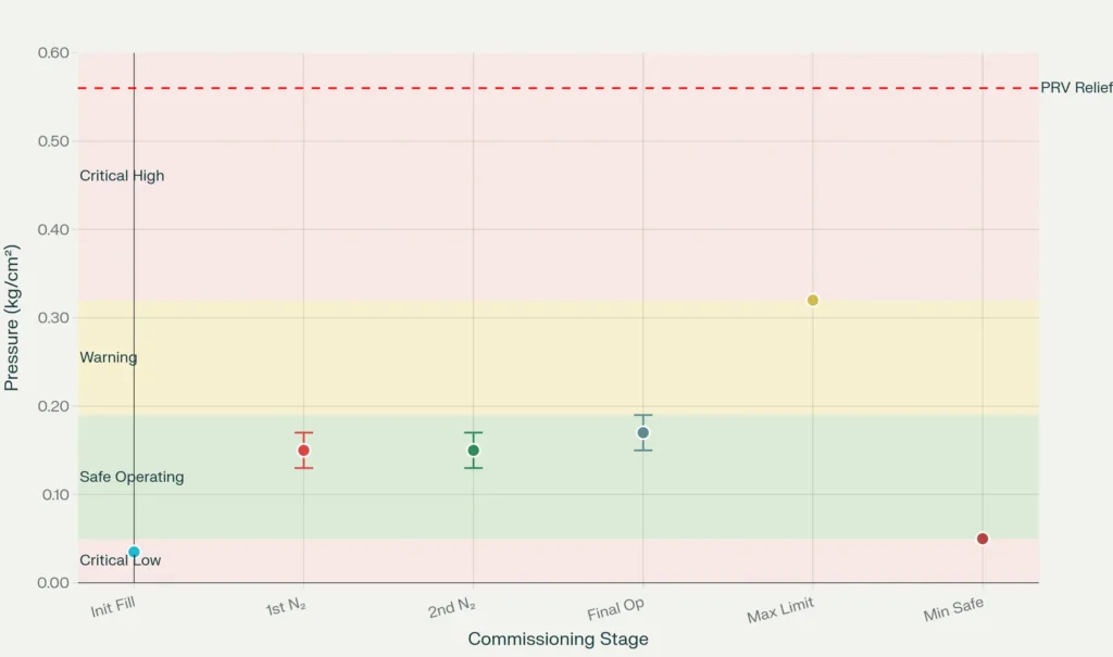
Air Cell Pre-Charge Pressure: 0.035 kg/cm² (0.5 psi)
When a new transformer arrives with an air cell, the air cell is pre-charged to this relatively low pressure at the factory. This low initial pressure accommodates the need for pressure increases as the transformer is heated and oil is filled during commissioning.
During Transformer Commissioning (Vacuum Drying)
Transformers undergo an extensive drying process before being put into service. This process involves multiple cycles of vacuum application and nitrogen filling:
First N₂ Cycle Pressure: 0.15 ± 0.02 kg/cm² (approximately 2.1 psi)
After creating a vacuum in the transformer tank and breaking that vacuum with nitrogen, the pressure is brought to this level. The transformer is then heated (typically to 60-70°C at the tank wall) and held at this pressure for 36 hours. During this time, any remaining moisture evaporates and is removed through the nitrogen outlet valve.
Second N₂ Cycle Pressure: 0.15 ± 0.02 kg/cm² (approximately 2.1 psi)
After completing multiple vacuum-nitrogen cycles and confirming the dew point has reached acceptable levels (-30°C or lower), the pressure is maintained at this same level. The transformer is heated again and held for an additional period.
Normal Operating Pressure (After Oil Filling)
Operating Pressure: 0.17 ± 0.02 kg/cm² (approximately 2.4 ± 0.3 psi)
This is the target pressure maintained during normal transformer operation. It’s slightly higher than the commissioning pressure to account for normal temperature variations and minor pressure losses over time.
Minimum Safe Pressure: 0.05 kg/cm² (0.7 psi)
Below this pressure, the system loses its integrity. If pressure drops below 0.05 kg/cm², atmospheric air begins entering the transformer even without obvious leaks. This is why regular pressure monitoring is critical.
Maximum Permissible Pressure: 0.32 kg/cm² (4.6 psi)
This is the absolute maximum pressure allowed in the air cell. The Pressure Relief Valve (PRV) is typically set to open at 0.56 kg/cm² (8 psi), protecting the transformer from overpressure. If pressure reaches the maximum permissible limit, the system must be depressurized immediately.
Common Problems and Solutions
Problem: Silica Gel Changed Color Too Quickly
Cause: The breather may have been left unattended with the cap off, or the silica gel was already partially saturated when installed.
Solution: Replace with fresh silica gel. Verify that the breather is always properly capped when not in use and that the oil cup is functioning to trap moisture.
Problem: Oil Leaking from the Oil Cup
Cause: The oil cup has filled beyond capacity, usually from excessive moisture absorption or an air/oil interface that’s too low.
Solution: Drain and clean the oil cup. Verify that the transformer breather depth is adequate—if the silica gel chamber is exposed to the oil level, the cup will fill too quickly.
Problem: Transformer Operating with Saturated Silica Gel
Cause: Maintenance was deferred or the breather wasn’t inspected regularly.
Solution: Immediately regenerate or replace the silica gel. Draw an oil sample and send to a laboratory for moisture analysis (Karl Fischer test) to determine if moisture contamination occurred while the breather was saturated.
Case Study: Transformer Breather Failure
A 5 MVA, 33/11 kV Power Transformer serving a city hospital was being operated with a fully saturated silica gel breather displaying a deep pink color for more than 18 months. The maintenance team repeatedly deferred replacement, believing they could address it “when convenient.”
During a routine oil analysis and testing, it was discovered that the moisture content was at 3,500 ppm, nearly 70 times higher than the acceptable 30-50 ppm range. The saturated breather had become a liability, allowing contaminated air to enter the transformer continuously.
Immediate shutdown of the transformer was taken, resulting in a 6-hour complete power outage that disrupted patient care, requiring emergency backup systems. Internal inspection of the transformer revealed winding insulation degradation, corrosion on metal components, and oil requiring complete replacement. The equipment downtime lasted two weeks during remediation. During that period, load was shifted to another 5 MVA Transformer which was running in parallel.
After the complete maintenance of the transformer including vacuuming, the transformer was taken back in line. The facility then implemented monthly inspections on the transformer and regenerated silica gel before it reached dark pink saturation.
After that, zero breather-related failures have been detected over the past three years.
Key Lesson: This case demonstrates the importance of regular breather monitoring and preventive regeneration. Systematic monthly inspections and timely maintenance action prevent catastrophic failures and extended downtime in critical infrastructure.
Conclusion
The silica gel breather is one of the most cost-effective investments in transformer protection available. By removing moisture from incoming air during the transformer’s breathing cycle, it preserves the dielectric strength of insulating oil and protects critical internal components from corrosion and degradation.
Modern breathers combined with air cells and proper nitrogen pressure management create a comprehensive moisture protection system.