Three-phase induction motors are the workhorses of industrial electrical systems. They power everything from pumps and compressors to conveyors and manufacturing equipment. However, like all electrical machinery, they require systematic testing to ensure reliability, safety, and optimal performance.
In this technical guide, we will cover all essential testing procedures for three-phase induction motors, including visual inspections, continuity checks, insulation resistance measurements, winding resistance tests, and running amperage analysis. We’ll also explore practical examples, real-world scenarios, and industry standards to help you understand when to test, how to conduct each test, and how to interpret results.
Three Phase Induction Motor Basics
A three-phase induction motor is an AC motor that uses three alternating currents to generate rotation. It consists of several key components including the stator (fixed windings), rotor (rotating part), and bearings. These motors are incredibly efficient because the three-phase power supply creates a rotating magnetic field that naturally spins the rotor without needing brushes or commutators like DC motors.
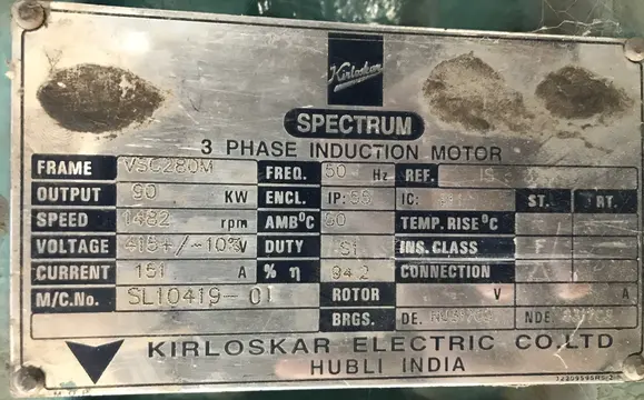
The motor’s nameplate provides crucial information that guides all testing decisions. Learning how to read a nameplate is your first step in proper testing. The nameplate typically shows the power rating (in kilowatts or horsepower), voltage rating (such as 415V for three-phase motors in India), current rating (in amperes), frequency (50 Hz or 60 Hz), power factor, efficiency, speed (in RPM), and the winding connection (delta or star).
For example, a nameplate might read: 5 HP / 3.5 kW, 415V AC, 50 Hz, 3 Phase, 7A, Power Factor 0.86, 1440 RPM.
Test 1: Visual Inspection
Visual inspection is often overlooked, but it’s important because many motor problems are visible before they cause serious damage. This should always be your first testing step because if the motor is badly damaged, further testing might not be safe or necessary.
During visual inspection, you should carefully examine the motor’s exterior condition for burn marks, scorch marks, or charring on the motor body, which indicate overheating or electrical faults. Check the cable insulation for cracks, cuts, or deterioration, as damaged cables can expose live conductors. Look for corrosion or rust on the motor frame and terminal box, which suggests the motor has been exposed to moisture or harsh environments. Inspect the cooling fan to ensure it’s clean and not blocked by dust or debris, as restricted airflow causes motors to overheat.
Also verify that all bolts and mechanical fasteners are tight, check for loose or corroded terminal connections, and ensure no objects are obstructing the motor shaft or rotor.
A practical example: a manufacturing facility discovered a broken cooling fan blade on a 10 HP motor during routine visual inspection. Replacing the fan blade before it disintegrated completely prevented a catastrophic failure and expensive downtime.
Test 2: Motor Nameplate Specifications
Reading the nameplate correctly is absolutely important because it tells you what values to expect during testing and which test procedures and voltages to use. Let’s work through a practical example using a common three-phase motor:
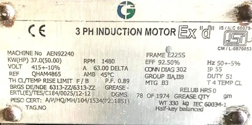
Example Motor Nameplate:
- Power Rating: 50 HP (37 kW)
- Voltage: 415V, 3 Phase
- Current: 63 Amperes (Full Load Current)
- Frequency: 50 Hz
- Power Factor: 0.89
- Efficiency: 92.5%
- Speed: 1480 RPM
- Insulation Class: F
- Design: Squirrel Cage
- Terminal Connections: Delta
From this nameplate, you know that the motor is designed to run on 415V three-phase supply, draw a maximum of 63 amperes under full load, and operate at approximately 1480 RPM. The insulation class “F” means the motor can operate up to 155°C. This information is essential because when you measure the current during the running amps test, you’ll compare it with the nameplate value of 63A to determine if the motor is operating correctly.
Test 3: Continuity Testing
The continuity test verifies that the motor’s three windings are electrically complete and unbroken. A broken winding means no current can flow through that path, and the motor cannot operate. This test should be done with the motor completely disconnected from power.
Equipment Needed:
- Digital Multimeter (preferably a high-precision resistance meter)
- Clean terminals
- Safety equipment (gloves, eye protection)
Step-by-Step Procedure:
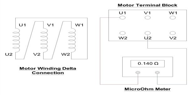
First, disconnect the motor from all power sources and allow any capacitors to discharge safely. Remove the terminal box cover to access the winding terminals. You’ll find six terminals labeled U1, U2, V1, V2, W1, and W2, representing the three phases (R, Y, B or U, V, W). The terminals might also be labeled T1, T2, T3, T4, T5, T6.
Set your multimeter to the lowest ohm range (typically 20 ohms). Connect the multimeter leads between U1 and U2 (the two terminals of phase 1). You should get a low resistance reading, typically between 0.1 and 10 ohms depending on motor size and winding design. The key point is that you should see continuity (the multimeter beeps or shows a resistance value, not infinity or open circuit).
Repeat this test for V1-V2 and W1-W2. The readings between all three phases should be approximately equal. If one phase shows significantly higher resistance or infinite resistance (no continuity), that winding is open or broken and the motor needs rewinding.
Practical Example:
Testing a 3-phase motor that wouldn’t start, you measure and get: U1-U2 = 3.2 ohms, V1-V2 = 3.5 ohms, W1-W2 = 340 ohms. This huge difference in W1-W2 indicates a broken winding in that phase. The motor failed the continuity test and must be rewound before it can be used.
Important Note: Some motors are internally connected in star or delta, which means you might only see three external terminals instead of six. In these cases, you need to know the internal connection before conducting the test, or the readings won’t make sense.
Test 4: Winding Resistance Measurement
Measuring winding resistance helps detect shorted turns, poor connections, and temperature-related problems. This test is different from continuity testing because it measures the actual resistance value rather than just checking if current can flow.
Key Point About Temperature: Winding resistance changes dramatically with temperature. Copper wire resistance increases by approximately 0.4% for every 1°C increase in temperature. This means a cold motor and a warm motor will show different resistance values even if they’re perfectly healthy. Always note the ambient temperature when taking readings and follow IEEE standard procedures for temperature correction.
Step-by-Step Procedure:
- Disconnect the motor from power and wait for it to cool if it was recently running
- Record the ambient temperature (room temperature) – this is very important
- Set your multimeter to resistance (ohms) mode
- Connect leads between U1-U2 and note the reading
- Repeat for V1-V2 and W1-W2
- All three readings should be very similar – typically within 5% of each other
Expected Values: For a healthy motor, if one phase reads 3.0 ohms, another should read between 2.85 and 3.15 ohms. If you see one phase at 3.0 ohms and another at 2.0 ohms, this suggests problems with that winding.
Practical Example:
Testing an old 7.5 HP motor before putting it back into service, you measure: U1-U2 = 4.2Ω, V1-V2 = 4.1Ω, W1-W2 = 4.0Ω. All readings are within 5% of each other and show smooth resistance values (no intermittent spikes), indicating healthy windings.
Why Balanced Resistance Matters: If the resistance values are not balanced, it can indicate turn-to-turn shorts (some wire turns shorted together within a coil), poor connections inside the motor winding, or previous overheating damage. Motors with unbalanced winding resistance may run, but they create heat imbalances and fail prematurely.
Also, check Winding Resistance Test of Power Transformers
Test 5: Insulation Resistance Testing
The insulation resistance (IR) test, commonly called “meggering” a motor, is perhaps the most critical test for determining motor health. This test checks whether the insulation between windings and the motor frame is in good condition. Poor insulation can cause electric shock hazards, ground faults, and catastrophic motor failures.
Why This Test Matters:
The insulation system is the motor’s defense against electrical failure. When insulation degrades, moisture and contaminants penetrate, creating low-resistance paths. An IR test applies a controlled high-voltage DC signal and measures how much current leaks through the insulation. Good insulation blocks this current (high megohms), while degraded insulation allows current to flow (low megohms).
Equipment Needed:

- Digital Megohmmeter (insulation resistance tester) capable of 500V DC
- Discharging tool or grounded screwdriver
How to Perform the Insulation Resistance Test:
Step 1 – Preparation:
First, disconnect the motor from all power sources. Wait at least 5 minutes for the motor to cool to ambient temperature. Record the ambient temperature – this is critical because temperature dramatically affects IR readings. IEEE 43 standard specifies that results should be corrected to 40°C.
Step 2 – Safety Discharge:
Even with power disconnected, the motor windings may store electrical charge. Use an insulated screwdriver or dedicated discharge tool to carefully short the motor terminals to ground, dissipating any stored energy. This prevents dangerous shocks during testing.
Step 3 – Megger Setup:
Set your megohmmeter to 500V DC for motors rated up to 1000V. For higher-voltage motors, use higher test voltages (typically 1000V or higher) per IEEE recommendations. Connect the red lead to one motor winding terminal and the black lead to the motor frame or ground.
Step 4 – Testing Each Phase:
- Connect red lead to U1 and black lead to motor frame
- Press the test button and hold for exactly 1 minute
- Read the value at 1 minute – this is your IR reading
- Record this value
- Discharge the motor again using your discharge tool
- Repeat for V1 and W1
- Also test phase-to-phase (U1 to V1, V1 to W1, U1 to W1) – these should show even higher values
Step 5 – Interpreting Results:
After 1 minute of applied voltage, expect to see megohm readings. The absolute minimum varies by motor age and type, but IEEE 43-2000 Standard provides clear guidance:
- Form-wound coils (motors built after 1970): Minimum of 100 MΩ regardless of voltage
- Random-wound stator coils below 1 kV: Minimum of 5 MΩ
- Older motors (before 1970): Use formula of 1 MΩ + 1 MΩ per kV rating
- Example: A 10 kV motor from 1960 should have at least (1 + 10) = 11 MΩ
Practical Example 1 – Good Motor:
Testing a 415V motor installed recently, your megohmmeter reading at 1 minute is 500 MΩ. This is excellent – far above the 5 MΩ minimum for a below-1kV random-wound motor.
Practical Example 2 – Questionable Motor:
Testing an older 415V motor recovered from storage, the reading is 2 MΩ at 1 minute. This is below the 5 MΩ minimum and indicates the motor has absorbed moisture or the insulation has degraded. The motor should not be used until the insulation is restored (typically by oven drying).
Practical Example 3 – Failed Motor:
Testing a motor that stopped working, the reading jumps to “0” or stays at nearly zero. This indicates severe insulation failure – there’s essentially no insulation left between the windings and frame. This is a serious safety hazard and the motor must be removed from service immediately.
Temperature Correction
If your motor reads 3 MΩ at 20°C ambient temperature, you need to correct this to 40°C for comparison with standards.
Using IEEE guidelines, insulation resistance doubles for every 10°C decrease below 40°C.
So 3 MΩ at 20°C becomes 3 × 4 = 12 MΩ at 40°C (20°C is 20°C below 40°C, so multiply by 2 four times).
This corrected value of 12 MΩ exceeds the 5 MΩ minimum, so the motor passes.
Polarization Index (PI):
Some technicians measure IR at both 1 minute and 10 minutes to calculate the Polarization Index (PI = 10-minute reading ÷ 1-minute reading).
A PI above 2.5 indicates good insulation, while PI below 1.25 indicates poor insulation requiring further investigation. However, according to IEEE 43, the PI test becomes unreliable when the 1-minute IR exceeds 5000 MΩ.
Test 6: Earth/Ground Continuity Testing
The earth continuity test (also called ground continuity test) verifies that the motor frame is properly grounded. This is a critical safety test because improper grounding can result in electric shock hazards if a winding-to-frame fault occurs.
Purpose: The motor frame must provide a low-resistance path to ground so that if there’s an accidental contact between a live winding and the frame, the fault current flows safely to ground instead of through a person who might touch the motor.
Step-by-Step Procedure:
- Set multimeter to continuity or ohms mode
- Place one probe on the motor frame (typically at designated grounding point)
- Place the other probe on a known earth/ground connection, such as the facility’s main ground, a ground rod, or the building’s grounding system
- Take the reading – it should be less than 0.5 ohms
- If the reading is greater than 0.5 ohms, the grounding connection is suspect and the motor should not be used until the grounding is improved
Practical Example: Before installing a 10 HP motor in a manufacturing facility, you test the earth continuity. The reading is 0.3 ohms, which is excellent – well below the 0.5 ohm limit. The motor is safe to install and use.
Test 7: Running Amperage Test
The running amps test or load test measures the actual current draw while the motor is operating. This test shows whether the motor is operating within its design parameters and helps identify problems like unbalanced supply voltage, overloading, internal faults, or excessive friction.
Equipment Needed:
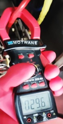
- Digital Clamp Meter (capable of measuring AC current)
- The motor in normal operating condition
- Motor nameplate information
- PPE including insulated gloves
Step-by-Step Procedure:
- Start the motor under its normal load conditions and allow it to run for 5-10 minutes to reach steady-state operation
- Use the clamp meter to measure current on each phase (L1, L2, and L3). Open the clamp around each wire without touching the wire itself
- Record the reading from each phase
- Compare each reading with the Full Load Current (FLC) nameplate value
Full Load Current (FLC):
The nameplate FLC is the maximum current the motor should draw during normal full-load operation. For our earlier example motor rated at 415V, 5 HP, the nameplate showed 7 amperes. This means:
- If motor draws 5.5 amperes (78% of FLC) = Motor is running at partial load – normal and healthy
- If motor draws 7.0 amperes (100% of FLC) = Motor is running at full load – this is where it’s designed to operate
- If motor draws 7.5 amperes (107% of FLC) = Motor is overloaded – investigate for excessive friction, mechanical problems, or undersized motor
- If motor draws 9.0 amperes (129% of FLC) = Motor is severely overloaded – risk of overheating and failure
Phase Balance Check:
The three phases should draw nearly equal current. A significant difference (more than 10%) between phases indicates:
- Unbalanced supply voltage at the facility
- Internal motor faults like winding problems
- Loose connections
Practical Example 1 – Healthy Motor:
A 10 HP motor with nameplate FLC of 13.5 A is running in a manufacturing plant. Using the clamp meter, you measure: Phase 1 = 12.8 A, Phase 2 = 13.2 A, Phase 3 = 13.0 A. The average is 13.0 A (96% of FLC), the balance is excellent (within 1-2% between phases), and the motor is running smoothly. Everything checks out perfectly.
Practical Example 2 – Motor with Problems:
An older motor with nameplate FLC of 15 A shows current readings of: Phase 1 = 16.5 A, Phase 2 = 15.2 A, Phase 3 = 14.1 A. The average current is slightly high (15.3 A = 102% of FLC), but more concerning is the phase imbalance – Phase 1 is 2.4 A higher than Phase 3 (a 17% difference). This suggests unbalanced supply voltage or an internal motor fault. Further investigation is needed.
Test 8: No-Load Test and Blocked Rotor Test
For larger motors (typically 20 HP and above), more sophisticated testing procedures can determine equivalent circuit parameters and predict performance characteristics. These tests are common in electrical engineering labs and during motor commissioning.
No-Load Test (Open Circuit Test):
In the no-load test, the motor runs at full rated voltage and frequency without any mechanical load connected. This test measures the motor’s no-load current, power factor, and power consumption. The input power during no-load operation represents the motor’s iron losses, windage losses, and friction losses.
Key measurements include:
- No-load voltage (V₀) – should equal rated voltage
- No-load current (I₀) – typically 20-30% of full-load current
- No-load power (W₀) – represents constant losses
- Stator resistance per phase (R₁) – measured using multimeter
Blocked Rotor Test:
In the blocked rotor test, the motor’s rotor is mechanically locked so it cannot rotate, and a reduced voltage is applied to the stator. The voltage is gradually increased until the motor draws its full-load rated current. This test measures the motor’s leakage impedance, rotor resistance, and allows calculation of the motor’s full-load copper losses (I²R losses).
Important points:
- The voltage used is much lower than rated (typically reduced by 60-75%)
- For best results with large motors (20 HP+), apply the test voltage at 1/4 the rated frequency per IEEE recommendations to minimize core losses
- The test must be completed quickly (within minutes) to avoid overheating the windings
- Never apply full rated voltage during blocked rotor test – this will damage the motor
These advanced tests require specialized equipment and expertise, and are typically performed by:
- Electrical engineering laboratories during motor design and testing
- Motor manufacturers during quality control
- Specialized motor testing companies providing commissioning services
- University electrical engineering departments in educational settings
Preventive Maintenance Schedule for Motors
Implementing a regular testing schedule helps prevent unexpected failures and extends motor life. Based on motor type, size, and operating environment, here’s a recommended maintenance schedule:
Weekly Inspections:
- Visual inspection for cleanliness, unusual noise, or vibration
- Check bearing and motor temperatures using infrared thermometer
- Listen for abnormal sounds
- Verify cooling fan operation using stroboscope
- Check for water or corrosion
Monthly Maintenance:
- Perform continuity and short-circuit tests on critical motors
- Measure and record winding resistance (compare with previous readings)
- Perform megger test (IR test) if conditions warrant (moisture exposure, operational stress)
- Measure operating current (running amps test) and compare with nameplate
- Inspect and tighten terminal connections
- Clean motor surfaces and cooling vents
Biannual Maintenance (Annual or Semi-Annual):
- Full insulation resistance test with temperature correction
- Winding resistance temperature coefficient analysis
- Perform polarization index (PI) test for critical motors
- Vibration analysis to detect bearing wear
- Thermal imaging to detect hot spots
- Check footing and mechanical mounts
Annual or As-Needed:
- No-load test and blocked rotor test for large motors
- Professional bearing inspection or replacement
- Cleaning of motor interior
- Oil analysis for sleeve bearing lubrication condition
Emergency Testing (Immediately):
- When motor shows signs of overheating
- After unusual noise or vibration
- Following power supply problems or lightning strike
- If motor fails to start
- If circuits trip repeatedly
Safety Considerations During Motor Testing
Before and during any motor testing, follow these safety rules strictly:
- Always disconnect power – Even when you think power is off, verify it using a voltage detector on the line side of the disconnect switch
- Discharge the motor – Use an insulated screwdriver to short the terminals to ground after disconnecting power
- Use proper PPE – Wear insulated gloves rated for the voltage level, safety glasses, and closed-toe shoes
- Never perform tests on energized circuits – Wait for dedicated test contacts or use equipment designed for live testing
- Keep the test area clear – Don’t test in wet or damp environments; work on dry surfaces
- Respect high-voltage test equipment – A megohmmeter applies lethal voltage; treat it with extreme caution
- Never megger a motor still connected to a drive – The drive’s electronics may be damaged; always disconnect the motor completely
- Keep discharge tool handy – After megger testing, immediately ground all terminals before touching them
Summary Table for Quick Reference
| Test | Equipment | Time Required | Key Value to Record |
|---|---|---|---|
| Visual Inspection | Eyes only | 5 minutes | Observations |
| Continuity Test | Multimeter | 10 minutes | Ohms between terminals |
| Winding Resistance | Multimeter | 15 minutes | Resistance in ohms |
| IR Test (Megger) | Megohmmeter | 10 minutes | Megohms at 1 minute |
| Earth Continuity | Multimeter | 5 minutes | Ohms to ground |
| Short Circuit Test | Multimeter | 5 minutes | Continuity yes/no |
| Running Amps | Clamp Meter | 15 minutes | Current in amperes |
| No-Load Test | Wattmeter setup | 20 minutes | Voltage, Current, Power |
| Blocked Rotor | Specialized | 15 minutes | Voltage, Current, Power |
Practical Troubleshooting Examples
Example 1: Motor Won’t Start
Scenario: A manufacturing facility calls you to troubleshoot a 7.5 HP pump motor that won’t start.
Testing procedure:
- Visual Inspection: Motor is clean, connections look tight, cooling fan turns freely
- Continuity Test: U1-U2 = 2.8Ω, V1-V2 = 2.9Ω, W1-W2 = ∞ (infinite – no continuity)
- Diagnosis: Winding W is open (broken wire inside)
- Solution: Motor must be sent for professional rewinding; cost approximately 30-40% of new motor price
Example 2: Motor Runs But Drawing Too Much Current
Scenario: A 15 HP compressor motor has been running slowly and noisily for several days.
Testing procedure:
- Visual Inspection: Motor temperature is hot to touch; no obvious damage
- Running Amps Test: Phase 1 = 22A, Phase 2 = 21A, Phase 3 = 19A (nameplate FLC = 20A). Average is 20.7A (103.5% of FLC)
- Insulation Resistance Test: 45 MΩ – still above 5 MΩ minimum but declining
- Phase Balance: 3A difference between phases – significant imbalance
- Diagnosis: The motor is struggling; likely causes are mechanical overload, bearing wear, or early insulation degradation
- Recommendation: Reduce load, perform bearing inspection, schedule motor rewinding within next maintenance cycle
Example 3: Motor Works But Smells Burning
Scenario: A 3 HP fan motor smells like burning insulation but still turns on and runs.
Testing procedure:
- Visual Inspection: No external burn marks visible; smell is coming from motor vent
- Insulation Resistance Test: 2 MΩ at 25°C (below the 5 MΩ minimum); significantly below standard
- Temperature Correction: Correcting to 40°C: 2 × 2 = 4 MΩ (still below minimum)
- Running Amps Test: All phases draw 90% of FLC – seemingly normal, but combined with low IR this is concerning
- Diagnosis: Insulation is degrading, likely from overheating or moisture ingress. The burning smell indicates active insulation breakdown
- Solution: Disconnect motor immediately; this is a safety and fire hazard. Send for professional oven drying and possible rewinding
Conclusion
Testing three-phase induction motors is a skill that combines technical knowledge, careful procedure, and practical judgment. By mastering these test procedures – from simple visual inspection through advanced no-load and blocked rotor testing – you gain the ability to diagnose motor problems before they cause catastrophic failures and expensive downtime. The key is to test systematically, follow safety procedures strictly, record all measurements, and compare results with established standards like IEEE 43.
Remember that early detection through regular testing prevents emergency failures. A motor that shows declining insulation resistance on your regular monthly tests should be scheduled for professional service before it fails. A motor with slightly unbalanced current draw might need attention to its mechanical load before the problem becomes critical. By knowing what each test reveals and what the results mean, you become a more effective electrical professional in manufacturing, maintenance, facility management, or electrical contracting.