Transformer cooling is one of the most important aspects of transformer design and operation. A transformer generates heat during its normal operation due to losses occurring in the core and windings. If this heat is not effectively dissipated, it can cause insulation degradation, accelerate aging of materials, and ultimately lead to transformer failure. The primary purpose of a cooling system is to maintain the transformer’s internal temperatures within safe limits for long service life and reliable operation.
The heat generated in a transformer comes from two main sources: core losses (hysteresis and eddy current losses) and copper losses (resistance losses in the windings).
These losses are proportional to the transformer’s load and operating conditions. Without an effective cooling system, the internal temperature would rise rapidly, damaging the insulation system and shortening the transformer’s lifespan.
Heat Generation in Transformers
To understand cooling requirements, it is essential to first understand how heat is generated within a transformer.
When current flows through the transformer windings, energy is dissipated as heat due to the resistance of the copper conductor. This is represented mathematically as I²R losses, where I is the current and R is the resistance. Similarly, when the core is magnetized, energy is lost due to the magnetic properties of the core material, resulting in core losses.
The total heat generated in a transformer is expressed as:
Total Losses = Core Losses + Copper Losses (Load Losses)
Consider a practical example: a 250 kVA distribution transformer operating at full load may generate approximately 8-10 kW of heat. Without a proper cooling system, the internal temperature of this transformer would rise dangerously high within minutes, potentially reaching temperatures above 200°C. With an adequate cooling system, this heat is continuously removed, maintaining the winding temperature at around 50-80°C above the ambient temperature.
Cooling Medium and Its Properties
The cooling medium is the substance responsible for carrying heat away from the transformer’s internal components to the external environment. Different cooling media have different thermal properties and are selected based on the transformer’s application and capacity.
1. Mineral Oil as Cooling Medium
Mineral oil is the most commonly used cooling medium in power transformers. It serves a dual purpose: it acts as both an insulating fluid and a cooling medium.
Mineral oil has excellent electrical insulation properties with a breakdown voltage typically ranging from 30-70 kV. It also has good thermal conductivity, allowing efficient heat transfer from the windings and core to the outer surfaces of the transformer tank.
The advantages of mineral oil include cost-effectiveness, proven long-term reliability, and compatibility with standard transformer designs.
However, mineral oil has a lower biodegradability rating and a relatively lower ignition temperature compared to alternative fluids. Its viscosity changes with temperature, which affects cooling efficiency at different operating points.
2. Alternative Cooling Fluids
Modern transformers increasingly use alternative cooling fluids that offer environmental and safety advantages:
- Natural Ester Oil is derived from renewable plant-based sources and offers superior biodegradability. It has a higher ignition temperature (around 350°C compared to mineral oil’s 180°C) and better cooling properties at elevated temperatures. Natural ester oil is preferred in environmentally sensitive locations and for transformers installed indoors in urban areas.
- Synthetic Ester Oil provides a balance between mineral oil and natural ester, with good thermal properties and environmental benefits. It offers excellent fire safety characteristics and is suitable for high-temperature applications.
- Silicone Oil is another alternative that provides excellent thermal stability and fire safety but is significantly more expensive than mineral oil. It is used in specialized applications where extreme fire safety is required.
- Nanofluids represent an emerging technology where nanoparticles are suspended in the base oil to enhance thermal conductivity. Research has shown that nanofluids can improve cooling efficiency by 15-20% compared to conventional mineral oil, though this technology is still in development for commercial applications.
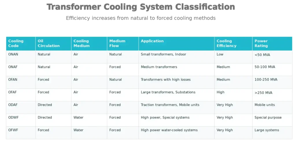
Cooling System Classification and Codes
Transformer cooling systems are classified based on two parameters: the method of oil circulation and the method of cooling medium circulation. The industry standard classification system uses a four-letter code that describes each aspect of the cooling method.
The Cooling Code
The cooling code consists of four letters, each representing a specific function:
First letter – Method of oil circulation within the transformer
- O = Oil-immersed
- A = Air-cooled (dry type)
Second letter – Method of cooling medium circulation
- N = Natural circulation
- F = Forced circulation
- D = Directed circulation (specific flow paths)
Third letter – Type of cooling medium
- A = Air
- W = Water
Fourth letter – Method of cooling medium circulation for the external cooler
- N = Natural circulation
- F = Forced circulation
Seven Major Cooling System Types
1. ONAN (Oil Natural Air Natural) Cooling
ONAN cooling is the simplest form of transformer cooling, relying entirely on natural circulation principles.
The oil inside the transformer becomes heated near the core and windings, causing it to rise due to reduced density. This hot oil moves upward and transfers heat to the inner walls of the tank. The tank’s outer surface then radiates heat to the surrounding air through natural convection. Simultaneously, cooler oil descends back toward the core, creating a continuous circulation pattern.
ONAN cooling is used for small to medium transformers with power ratings typically below 50 MVA. These transformers are usually found in indoor installations, pole-mounted distributions, or in areas with favorable ambient temperatures.
The advantages of ONAN cooling include absence of moving parts, minimal maintenance requirements, and silent operation. However, the cooling efficiency is limited, and the transformer cannot handle high thermal loads.
2. ONAF (Oil Natural Air Forced) Cooling
ONAF cooling improves upon ONAN by adding forced air circulation to the radiator fins. The oil circulation within the transformer remains natural, driven by buoyancy forces. However, cooling fans are mounted on the radiator to force air circulation over the fins, significantly increasing the heat transfer rate.
ONAF systems are suitable for medium-sized transformers with ratings between 50 MVA and 100 MVA. The cooling fans are controlled by thermostat switches that turn on when the top oil temperature exceeds a preset threshold (usually around 50-55°C) and turn off when it drops below another threshold.
The key advantage of ONAF cooling is improved cooling efficiency compared to ONAN while maintaining natural oil circulation. The forced air circulation increases the heat transfer coefficient at the radiator surface, allowing the transformer to handle higher loads. The disadvantage is the addition of moving parts (fans) that require periodic maintenance.
3. OFAN (Oil Forced Air Natural) Cooling
OFAN cooling uses forced oil circulation through the core and windings but relies on natural air circulation at the radiator. An oil pump circulates the oil through specific flow paths designed by engineers to maximize cooling effectiveness. This directed oil flow ensures that all parts of the windings receive adequate cooling fluid.
OFAN systems are used for transformers with high internal losses where natural oil circulation alone is insufficient. These are typically transformers in the 100-250 MVA range or units with compact designs where space is limited. The forced oil circulation allows for better temperature distribution and ensures that even the bottom portions of windings receive adequate cooling.
The primary advantage is improved winding temperature distribution and the ability to operate at higher loads compared to natural circulation methods. However, the oil pump adds complexity, cost, and maintenance requirements to the cooling system.
4. OFAF (Oil Forced Air Forced) Cooling
OFAF cooling combines forced oil circulation with forced air circulation, providing the highest cooling efficiency among air-cooled systems. Both the oil pump and cooling fans operate to remove maximum heat from the transformer.
OFAF systems are used for large power transformers with ratings exceeding 250 MVA and for transformers operating in high-temperature environments. A 350 kVA OFAF transformer might be found in a major substation serving a large industrial complex or an urban area with peak load demands. In such applications, the transformer must operate continuously at or near full load, requiring maximum cooling capability.
The advantages of OFAF cooling include excellent heat dissipation capability, ability to operate under high load conditions, and flexibility to operate at partial loads by controlling fan speed. The disadvantages include higher initial cost, greater complexity in control systems, and higher maintenance requirements for both pumps and fans.
5. ODAF (Oil Directed Air Forced) Cooling
ODAF cooling uses oil directed through specifically designed internal paths (ducts and baffles) that guide the cooling fluid to the hottest regions of the transformer. This directed circulation provides superior cooling to forced oil circulation methods. The air at the radiator is also forced, creating a dual-forced cooling system.
ODAF systems are commonly used in traction transformers for railway applications and mobile power transformers. These transformers often have space constraints and compact designs, making directed cooling essential for effective thermal management. A mobile substation transformer with a capacity of 50-100 MVA typically uses ODAF cooling to fit within the physical constraints of a trailer-mounted unit.
The main advantage is optimal temperature distribution with minimal temperature differences between various parts of the winding. The disadvantage is the complex internal design of the transformer, which increases manufacturing complexity and cost.
6. ODWF (Oil Directed Water Forced) Cooling
ODWF cooling replaces air with water as the external cooling medium. Water has superior thermal properties compared to air, allowing much higher heat dissipation rates with smaller heat exchanger sizes. The oil is directed through internal cooling paths and then passed through a water-cooled heat exchanger.
ODWF systems are used for very high power transformers (above 500 MVA) and in locations where compact design is essential. For example, large grid transformers in metropolitan substations with space limitations may use ODWF cooling. These systems require careful management of water quality to prevent corrosion and fouling of the cooling tubes.
The advantages include superior cooling efficiency, compact design, and the ability to operate at very high power ratings. The disadvantages include dependence on external water supply, risk of water-side fouling, and higher maintenance complexity.
7. OFWF (Oil Forced Water Forced) Cooling
OFWF cooling is similar to ODWF but uses forced oil circulation instead of directed circulation. Both the oil and water are circulated by pumps through their respective systems. This method provides excellent cooling capability for high-power transformers.
OFWF systems are used in specialized high-power applications and combined thermal systems where both forced oil circulation and water cooling are beneficial. These are less common than ODAF or ODWF in typical utility applications but are found in large industrial transformers.
Temperature Considerations and Limits
Winding Hot Spot Temperature
The hot spot is the point within the transformer winding that reaches the highest temperature during operation. This temperature is critical because insulation aging rates are primarily dependent on the temperature at this hottest point. The hot spot temperature depends on several factors including the winding design, oil circulation pattern, and the quality of cooling in that particular region.
The relationship between ambient temperature and winding temperature can be expressed as:
Winding Temperature = Ambient Temperature + Oil Temperature Rise + Additional Winding Rise
For example, consider a transformer operating with an ambient temperature of 40°C and an oil temperature rise of 40°C above ambient. If the winding has an additional temperature rise of 20°C above the bulk oil temperature due to localized high current density, the winding hot spot temperature would be 40 + 40 + 20 = 100°C.
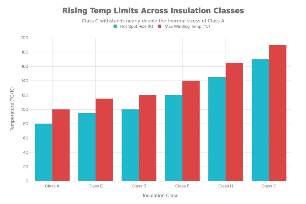
Temperature Rise Limits
Different insulation materials have different temperature ratings, classified according to international standards. These classes determine the maximum hot spot temperature that the transformer can withstand over its lifetime.
- Class A Insulation (traditional cotton and paper) has a maximum winding temperature limit of 100°C and a hot spot rise of 80 K above a 40°C ambient. Transformers with Class A insulation are rarely manufactured today but may still be found in older installations.
- Class E Insulation is rated for a maximum winding temperature of 115°C with a hot spot rise of 95 K. These transformers are suitable for continuous operation in moderate climates.
- Class B Insulation (typically using synthetic paper or advanced materials) allows a maximum winding temperature of 120°C with a hot spot rise of 100 K. This is commonly used in modern distribution transformers.
- Class F Insulation is rated for 140°C maximum winding temperature with a hot spot rise of 120 K, providing additional margin for operation in high-temperature environments.
- Class H Insulation allows up to 165°C with a hot spot rise of 145 K and is used in transformers designed for hot climates or high-load applications.
- Class C Insulation provides the highest temperature rating at 190°C with a hot spot rise of 170 K, used in specialized high-temperature applications.
Cooling System Components and Maintenance
An effective transformer cooling system consists of several important components that must function together properly.
Radiator
The radiator is an extended surface heat exchanger that increases the surface area available for heat transfer. Transformers may have one or several radiators depending on the power rating and cooling requirement. Radiators consist of tubes through which hot oil flows, connected to cooling fins that greatly increase the surface area exposed to air.
Radiator fins must be kept clean to maintain optimal cooling efficiency. Dust accumulation, insect nests, or corrosion on the fins can reduce cooling effectiveness by 20-30%. Regular visual inspection and cleaning are essential maintenance tasks.
Cooling Fans
Cooling fans in forced air-cooled transformers are typically small electric motors with propeller-type blades. They are mounted on radiators to force air over the cooling fins. Fans should be inspected for bearing wear, vibration, and corrosion.
Fan blades should be checked for cracks or damage, and the motor bearings should be lubricated according to manufacturer specifications. A failing fan bearing produces characteristic squealing sounds before complete failure occurs.
Oil Pump
In forced or directed oil circulation systems, an electric pump drives oil circulation. These pumps must operate reliably for thousands of hours. Pump maintenance includes checking for leaks, monitoring bearing temperature, and ensuring smooth operation.
Pump cavitation (formation of air bubbles in the oil) can damage pump impellers and should be avoided through proper system design and maintenance.
Temperature Sensors and Thermostats
Modern transformers use temperature sensors to monitor oil and winding temperatures. These include resistance temperature detectors (RTD) and, in advanced systems, fiber optic sensors that provide precise temperature distribution measurements.
Thermostats controls when cooling fans and pumps to be turn on and off based on preset temperature thresholds. These devices must be calibrated regularly for accurate operation.
Oil Coolers (Heat Exchangers)
In water-cooled systems, oil-to-water heat exchangers facilitate efficient heat transfer between the transformer oil and external cooling water. These must be inspected for scale buildup on the water-side tubes and for any signs of corrosion or leakage.
Transformer Cooling Logics: Control Strategies and Automatic Operations
Transformer cooling logics are the automated control systems that manage when and how cooling devices (fans, pumps) operate based on real-time temperature conditions. These logics ensure that cooling capacity is deployed efficiently, reducing energy consumption while maintaining safe operating temperatures. Modern transformers use sophisticated control algorithms to optimize the balance between cooling effectiveness and operational cost.
Basic Cooling Logic Principles
The fundamental principle behind transformer cooling control is simple: cooling devices should operate at the minimum level necessary to maintain safe temperatures. This minimizes power consumption of cooling devices and extends their operational lifespan. The control logic continuously monitors temperature parameters and makes decisions about which cooling stages to activate.
The core inputs to any cooling logic system include:
Top Oil Temperature (TOT) is the primary monitoring parameter, measured by temperature sensors immersed in the transformer tank oil. This temperature reflects the average thermal condition of the transformer and serves as the primary trigger for fan and pump activation. Typical monitoring ranges are from 20°C to 100°C, with precision requirements of ±1°C.
Winding Hot Spot Temperature (HST) is the highest temperature point within the transformer windings. Since this cannot be directly measured in operating transformers (due to inaccessibility), it is estimated using thermal models based on load current, top oil temperature, and time constant parameters specific to each transformer design.
Load Current or Apparent Power indicates the transformer’s power throughput and is directly proportional to heat generation. Higher loads generate more heat and may require cooling stage activation even at moderate oil temperatures.
Ambient Temperature is the external air temperature around the transformer. The control logic compares the oil temperature rise above ambient (not the absolute oil temperature) to determine cooling requirements.
Two-Stage and Multi-Stage Cooling Logic
Most medium to large transformers use multi-stage cooling logic that progressively increases cooling capacity.
Stage 0: Natural Circulation (Base Condition)
In the base condition, no additional cooling devices are operating. This stage applies to ONAN transformers continuously and to ONAF/OFAF transformers during light loads. Heat is dissipated naturally through the tank surface and radiators without mechanical assistance. This stage is the most energy-efficient as it consumes zero cooling power.
Stage 0 operates continuously until the top oil temperature rises above the first stage setpoint. For example, in a typical 100 kVA ONAF transformer, Stage 0 remains active until the top oil temperature exceeds 45-50°C above ambient.
Stage 1: Forced Air Cooling (First Cooling Stage)
When the top oil temperature exceeds the first stage setpoint (typically 50-55°C above ambient, or absolute temperatures like 50-55°C), a thermostat relay activates the cooling fans. In ONAF systems, all fans start together. In more advanced systems, fans may start at reduced speed and progressively increase to full speed.
The activation of Stage 1 fans increases the convective heat transfer coefficient at the radiator surface. For an ONAF transformer, activating fans can improve cooling efficiency by approximately 40-50% compared to natural circulation alone. The combination of forced air circulation and natural oil circulation creates an effective intermediate cooling condition.
Stage 2: Enhanced Forced Cooling (Second Cooling Stage)
If the top oil temperature continues to rise above a second setpoint (typically 60-65°C above ambient), additional cooling measures activate. In OFAF transformers, the oil pump starts, forcing oil circulation through designed paths. In some designs, additional cooling fans may start, or existing fans operate at higher speeds.
Stage 3: Maximum Cooling (Third Cooling Stage)
If temperatures continue rising beyond the second stage setpoint (typically 70-75°C above ambient), all cooling systems operate at maximum capacity. Both pumps and fans run at full speed. In water-cooled systems, cooling water flow to the heat exchangers increases to maximum rates. Alarms and notifications are typically triggered at this stage to alert operators to abnormal conditions.
Control Logic Implementation Methods
Modern transformers employ different control logic architectures depending on their sophistication level and application.
Electromechanical Thermostat Logic
The simplest implementation uses bimetallic thermostat switches. A bimetallic strip expands and contracts with temperature changes, mechanically closing contacts when temperature exceeds setpoints. Each cooling stage has its own thermostat set at a specific temperature threshold.
In this approach, thermostats are arranged in series for successive stages, meaning Stage 2 cannot activate unless Stage 1 is already operating. This ensures proper progression through cooling modes. The activation sequence follows the temperature rise, providing automatic protection without external power requirements (apart from the cooling devices themselves).
A typical thermostat controller might have the following setpoints:
- Stage 1 activation: 50°C top oil
- Stage 1 deactivation (hysteresis): 45°C top oil
- Stage 2 activation: 60°C top oil
- Stage 2 deactivation: 55°C top oil
The hysteresis (5°C difference between turn-on and turn-off) prevents hunting—rapid cycling on and off that would damage equipment. This hysteresis band is essential for controller stability and equipment protection.
Programmable Logic Controller (PLC) Based Logic
Advanced transformers use PLC systems that implement sophisticated control algorithms. These systems read temperature sensors continuously and execute programmed logic to determine cooling stage status.
PLC-based systems offer significant advantages over simple thermostats:
First, they enable variable speed control. Rather than fans and pumps operating at full speed or off, they can modulate speed proportionally to cooling demand using variable frequency drives (VFDs). This reduces energy consumption significantly—reducing fan speed from 100% to 70% can reduce power consumption by nearly 50% (since fan power is proportional to cube of speed).
Second, they allow predictive control logic. Instead of reacting only to current temperatures, the system can predict future temperatures based on load trends and activate cooling stages preemptively. This prevents temperature overshoot and maintains more stable conditions.
Third, they enable load-based logic. The system activates cooling stages based on transformer load and forecasted load changes, not just current temperatures. During a rapid load increase, the system can activate cooling stages immediately, knowing that temperature will rise shortly.
Fourth, they provide data logging and remote monitoring. All temperature readings, cooling stage activations, and system events are recorded for analysis and remote monitoring via SCADA (Supervisory Control and Data Acquisition) systems.
A PLC-based system might implement logic similar to this pseudocode:
IF (Top Oil Temperature > 55°C) AND (Stage 1 NOT active) THEN
    Activate Cooling Fans (Stage 1)
    Record Event Timestamp
    Send Alert to SCADA
END IF

IF (Winding Hot Spot Temperature > 100°C) AND (Stage 2 NOT active) THEN
    Activate Oil Pump (Stage 2)
    Increase Fan Speed to 75%
    Record Event Timestamp
    Send High Priority Alert
END IF

IF (Winding Hot Spot Temperature > 120°C) THEN
    Send Critical Alarm
    Activate Load Shedding Signal
    Record Critical Event
END IF
Fuzzy Logic and Artificial Intelligence Control
The most advanced transformer cooling systems use fuzzy logic or machine learning algorithms. These approaches can handle multiple overlapping conditions and make nuanced decisions rather than binary on/off choices.
Fuzzy logic systems define membership functions for temperature inputs. Rather than saying “temperature above 55°C means activate Stage 1,” the system might define: “temperature in range 50-60°C has medium cooling requirement.” The output is similarly graduated: “run fans at 60% speed” rather than just “turn fans on.”
These systems provide smoother operation, faster response to changing conditions, and better coordination between multiple cooling devices. They can also learn from historical operational data to optimize setpoints for specific environmental conditions.
Special Considerations for Different Transformer Types
Dry-Type Transformers
Dry-type transformers use air as both the insulating and cooling medium. They eliminate the need for oil, reducing fire hazard and environmental concerns. Dry-type transformers typically use Class B, F, or H insulation.
Cooling in dry-type transformers occurs through natural convection air flow over the transformer windings or, in forced-cooled designs, through fans that blow air over the transformer surfaces. The absence of oil simplifies maintenance but typically requires larger physical dimensions to achieve adequate heat dissipation compared to oil-cooled designs.
Liquid-Immersed Transformers
Beyond mineral oil, modern liquid-immersed transformers may use natural ester, synthetic ester, or silicone oils. Each of these alternative fluids has different thermal properties affecting cooling system design.
Natural ester and synthetic ester oils generally have better cooling properties at elevated temperatures compared to mineral oil, allowing for slightly more compact cooling designs. Silicone oil’s excellent fire safety requires specialized cooling system design.
Cast Resin Transformers
These specialized transformers use epoxy resin casting instead of oil or air for insulation and cooling. The resin’s low thermal conductivity requires careful heat management through external cooling systems or enhanced designs.
Conclusion
Transformer cooling is fundamental to power system reliability. From ONAN’s simplicity to OFAF’s sophistication, cooling systems must match operational demands.
Proper temperature management through insulation classes ensures safe operation. Regular maintenance of radiators, fans, and pumps prevents failures. Real-time monitoring detects degradation early. Whether natural or forced circulation, every cooling stage serves a critical purpose. As power demands increase, advanced control logics optimize both efficiency and safety.