Transformer earthing, also known as grounding, is one of the most critical aspects of power system design and safety. It provides a safe path for fault currents to flow into the earth, protecting both personnel and equipment from dangerous electrical hazards. A properly designed earthing system ensures reliable operation of the power distribution network and prevents failures during electrical faults.
The earthing system at a transformer station serves multiple purposes: it limits overvoltages during faults, provides a reference point for the power system, protects personnel from electric shock, and enables protective devices to operate effectively. Without a robust earthing infrastructure, the entire power system becomes unstable and hazardous.
What is Transformer Earthing?
Transformer earthing is the process of connecting the transformer’s neutral point (or metallic body and tank) to the earth through a specially designed electrode system. This creates a low-resistance path for fault currents to dissipate safely into the ground during abnormal operating conditions.
Key Principle: When a phase conductor comes into contact with the transformer body or ground, the earthing system provides a return path for the fault current, allowing protective relays to detect the fault and isolate the faulty equipment.
The Earthing Path
The complete earthing path consists of three main components working together:
- Earthing Conductor: Copper or aluminum cable connecting the transformer neutral to the earthing pit
- Earthing Electrode: Metal rods or plates buried in the soil that interface with the earth
- Soil/Earth: The medium through which current flows and dissipates into distant earth
A typical earthing installation for a transformer substation might have copper conductors ranging from 50mm² to 120mm² in cross-section, connected to 8-12 vertical copper rods each 2-3 meters in length, buried in a specially prepared pit. The quality of each component determines the overall effectiveness of the earthing system.
Purposes of Transformer Earthing
1. Provides Return Path for Fault Current
During a phase-to-ground fault, the earthing system offers the lowest resistance path for fault current to return to the transformer neutral point. This rapid current flow triggers protective devices (relays, circuit breakers) to isolate the faulty section before equipment damage occurs. When fault current flows quickly through a dedicated path, the protective system can detect it almost instantaneously and disconnect the faulty equipment before dangerous levels of heat and stress develop.
In a 33 kV substation, a single-phase-to-ground fault might produce a fault current of 2,000-5,000 amperes. Without proper earthing, this current could create dangerous step and touch voltages around the substation, posing severe risk to personnel who might inadvertently come into contact with the ground surface.
2. Limits Ground Potential Rise (GPR)
When high fault currents flow into the earth, they create a potential difference between the ground electrode and distant earth (typically at infinity). This is called Ground Potential Rise (GPR), and it represents the voltage that the earthing system rises to above the potential of far away earth.
The relationship between GPR and the system parameters is expressed mathematically as:
\(V_{GPR} = I_f × R_g\)
Where \((I_f)\) is the fault current magnitude and \((R_g)\) is the earthing resistance.
If a fault current of 3,000 A flows and the earthing resistance is 1 ohm, the GPR would be 3,000 volts.
A properly designed system maintains earthing resistance below 1 ohm to limit dangerous potential rises, ensuring personnel safety and equipment protection. Lower resistance directly translates to lower dangerous voltages during faults.
3. Protects Equipment from Overvoltages
Transient overvoltages occurring during faults can reach values of 2-3 times the normal phase voltage. The earthing system, combined with surge arresters, ensures these overvoltages don’t exceed equipment insulation levels. These overvoltages arise from the sudden interruption of fault current and the energy stored in system inductances. By providing an effective earthing path, the system dissipates this energy safely and limits voltage stresses on equipment windings and insulation.
4. Provides Reference Potential
The earthing system establishes a zero reference point for the power system, enabling voltage measurements and protection system operations. All voltage in the system is measured relative to this earth reference. Without a stable earth reference, it becomes impossible to measure and monitor system voltages accurately, and protection relays cannot function reliably.
5. Enables Selective Protection Operation
Protective relays depend on sensing fault currents to operate correctly. An effective earthing system ensures sufficient fault current magnitude for relays to operate selectively and trip the correct breaker while leaving other parts of the system energized.
This selectivity prevents unnecessary disconnection of healthy parts of the network, maintaining power supply to the maximum possible area while isolating only the faulty section.
Earthing Resistance and Its Significance
Earthing resistance is the opposition to current flow from the electrode into the surrounding soil. It is the most important parameter determining the effectiveness of any earthing system. The lower the earthing resistance, the more effective the system becomes at dissipating fault current and limiting dangerous voltages.
Recommended Earthing Resistance Values
| Installation Type | Maximum Resistance | Reason |
|---|---|---|
| Power Transformer | < 1 Ω | Very high fault currents; needs low resistance |
| Distribution Transformer | < 2 Ω | Medium fault currents |
| Lightning Arrester Ground | < 5 Ω | Transient overvoltage protection |
| Low Voltage Equipment | < 5 Ω | Safety requirement |
| Substation Mesh | < 0.5 Ω | Multiple equipment sharing same ground |
Factors Affecting Earthing Resistance
Several critical factors influence earthing resistance, with some having significantly greater impact than others:
Soil Resistivity (most important factor)
Soil resistivity is the most important factor affecting earthing resistance, influencing it more than any other parameter. Measured in ohm-meters (Ω-m), soil resistivity varies significantly with soil composition, moisture content, and temperature.
Different soil types exhibit widely different resistivities:
- Clay soil: 50-100 Ω-m
- Alluvial soil: 100-200 Ω-m
- Sandy soil: 500-1000 Ω-m
- Rocky soil: 1000-3000 Ω-m
- Black cotton soil: 100-300 Ω-m
Depth of Electrodes
The depth of electrodes impacts resistance because deeper electrodes experience better soil resistivity. Moisture content increases with depth, and soil resistivity generally improves in lower layers.
The recommended minimum burial depth is 1.5-2.5 meters to access more stable soil conditions and higher moisture levels.
In dry climates, even deeper burial may be necessary to reach consistently moist soil.
Number and Configuration of Electrodes
The number and configuration of electrodes directly affects the total resistance. Resistance decreases with more rods arranged in parallel, and spacing between rods should be 1-3 times the rod length to minimize mutual interference effects.
When rods are placed too close together, they compete for the same soil volume, reducing their collective effectiveness. Proper spacing ensures each rod operates in fresh, undisturbed soil.
Moisture Content
Moisture content is directly proportional to soil conductivity, making it one of the most critical factors. Resistivity can decrease by 50% with a significant increase in moisture. The soil’s ability to conduct current depends heavily on the availability of moisture as a medium for ionic conduction.
During dry seasons, earthing resistance values increase noticeably, which is why design calculations should account for worst-case dry conditions.
Temperature
Temperature also affects soil resistivity, with higher temperature increasing resistivity. Earth resistance values change seasonally, being lowest in summer when soil moisture is maximum and highest in winter during dry periods. A well-designed system should account for these seasonal variations and be evaluated under worst-case conditions.
Main Types of Transformer Earthing Systems
1. Unearthed (Floating) Neutral System
In an unearthed system, the transformer neutral is not connected to earth. However, capacitive coupling between phase conductors and earth provides a high-impedance path for ground currents. The system essentially floats at some potential between ground and phase voltage, depending on the distribution of capacitances in the network.
The fault current magnitude in unearthed systems depends on system capacitance and typically ranges from 50-200 amperes. This very low fault current limits equipment damage since less energy is available for heating and arcing. Single-phase faults do not necessarily cause network disconnection, allowing supply to continue even after a fault occurs.
However, unearthed systems experience a high voltage rise on unfaulted phases during fault, reaching up to 1.73 × phase voltage. This places severe stress on insulation of healthy phases and adjacent equipment. Detecting single-phase faults becomes extremely difficult because the fault current is so small that conventional protection relays struggle to distinguish it from normal magnetizing current.
Additionally, if a second phase develops a fault before the first is repaired, the system can suddenly transition to a three-phase fault with very high current and severe consequences.
Characteristics and Features:
- Fault current: High (depends on capacitance)
- Voltage rise: 1.73 × phase voltage
- Equipment Protection: Low
- Supply Continuity: Excellent
- Complexity: Simple
Unearthed systems are mainly used in distribution networks up to 10 kV in some countries like France and Germany where the focus is on supply continuity rather than rapid fault detection.
Advantages:
- Excellent supply continuity during single-phase faults
- Minimal equipment stress from low fault currents
- Lower initial implementation cost
- Allows continued network operation during minor faults
Disadvantages:
- Very difficult to locate and detect faults
- Extremely high overvoltages on healthy phases
- Risk of two-phase faults escalating to three-phase faults
- Potential for extensive equipment damage from overvoltages
2. Solid (Directly) Earthed System
The transformer neutral is directly connected to the earthing electrode with minimal impedance between them, typically less than 0.5 ohm. This creates an extremely effective path for fault current to flow from the fault point through the neutral back to earth. The very low impedance means the fault current is limited only by the system’s source impedance.
In solid earthing systems, fault current can reach 5,000-10,000 amperes or higher, depending on system strength and transformer impedance. The voltage rise on unfaulted phases is limited to 1.4 × phase voltage since the neutral is held at ground potential by the solid connection. Immediate fault detection is possible because the fault current is large and easily detected by protection relays and instruments.
Characteristics and Features:
- Fault current: Very high (Ik = V/Z)
- Voltage rise: 1.4 × phase voltage
- Equipment Protection: Good
- Supply Continuity: Limited
- Complexity: Moderate
The major advantage of solid earthing is very low overvoltages during faults. Since the neutral is locked at ground potential, the voltage stress on healthy phases is minimized. However, the very high fault currents present significant challenges. Equipment must be rated for these high short-circuit currents, requiring expensive breakers, cables, and switchgear designed for very high ratings.
The mechanical stresses on conductors during fault clearing are enormous, and the Ground Potential Rise (GPR) hazard becomes severe, making the ground surface around the substation unsafe for personnel.
Advantages:
- Very low overvoltages during faults
- Rapid and reliable protection operation
- Simple and straightforward design
- Clear fault indication and detection
- Lower earthing system complexity
Disadvantages:
- Very high fault currents requiring expensive equipment
- Significant mechanical stresses on system components
- Large Ground Potential Rise creating personnel hazards
- Requires very high short-circuit rated switchgear
- Higher capital equipment costs
3. Resistance Earthing System
The transformer neutral is connected to earth through a resistor, limiting the fault current to a predetermined value selected during design. This resistor, called a Neutral Grounding Resistor (NGR), dissipates fault current energy as heat, controlling the maximum current that can flow.
The fault current in resistance earthing is typically limited to 100-600 amperes, a value carefully chosen based on the need to protect equipment while ensuring adequate fault detection capability.
The residual voltage on the earthing resistor during fault can reach 100-200 kV, requiring the resistor to be specifically designed and rated for these conditions. Overvoltages are limited to 1.4 × phase voltage, similar to solid earthing, making equipment insulation requirements reasonable.
The resistance value is calculated based on the desired fault current using:
\(R = \frac{V_{phase}}{I_{fault}}\)
Where \((V_{phase})\) is the phase-to-neutral voltage and \((I_{fault})\) is the desired fault current.
For a 33 kV system with a phase voltage of 19,050 V, if the desired fault current is 300 amperes, the required NGR would be 19,050 divided by 300, which equals 63.5 ohms. An NGR of 63-65 ohms would be selected and installed.
Characteristics and Features:
- Fault current: Medium (50-600A range)
- Voltage rise: 1.4 × phase voltage
- Equipment Protection: Excellent
- Supply Continuity: Good
- Complexity: Moderate
Advantages:
- Excellent control over fault current magnitude
- Superior equipment protection from limited stresses
- Reduced equipment lifetime degradation
- Faster and more sensitive relay operation possible
- Relatively low personnel hazard from limited GPR
- Good overall balance between protection and reliability
- Practical for widespread industrial and utility use
Disadvantages:
- Requires investment in specialized NGR equipment
- Complex engineering to select correct resistor value
- High voltage stress on the earthing resistor itself
- Potential overvoltages if not coordinated with surge arresters
- Regular maintenance and monitoring required
Resistance earthing is widely used globally in medium voltage distribution systems (3-35 kV), especially in industrial substations and utility distribution networks.
4. Impedance/Reactance Earthing System
The transformer neutral is connected to earth through an impedance, which can be resistive (resistor), reactive (reactor), or combined. This category includes several specialized techniques designed for specific applications.
Arc Suppression Coil (Peterson Coil): The inductive reactance is designed to compensate for line capacitance, which suppresses intermittent arc during ground faults. The fault current flow becomes minimal because the inductive and capacitive currents cancel each other. This technique is used primarily in European systems with isolated neutrals where supply continuity is critical.
Tuned/Resonant Earthing: The reactor inductance equals the capacitive reactance of the system, making the ground fault current approach nearly zero. This highly specialized application is used where continuous supply is absolutely essential, such as in hospitals or critical infrastructure.
Resonant Grounding with Resistance: This combines a reactor and resistor, suppressing arcs while limiting fault current. It performs better than pure inductive earthing because the resistance damps oscillations that can occur with reactors alone.
Characteristics and Features:
- Fault current: Medium-Low
- Equipment Protection: Excellent
- Supply Continuity: Excellent
- Complexity: High
Advantages:
- Excellent arc suppression during ground faults
- Superior supply continuity with minimal interruption
- Minimal transient overvoltages
- Better equipment insulation protection
- Selective phase-to-ground fault detection possible
Disadvantages:
- Very expensive specialized equipment required
- Complex tuning and control systems needed
- Requires specialized maintenance knowledge
- Regular system adjustment necessary as network changes
- Sensitive to rapid load variations
- Higher operational complexity
Treated and Untreated Earthing
Untreated Earthing
Untreated earthing refers to the installation of earthing electrodes in natural soil without any enhancement or additives. The earthing resistance depends entirely on the natural resistivity characteristics of the soil at the installation site, which can vary widely based on soil composition, moisture content, and seasonal changes.
In untreated earthing systems, the calculated resistance is based on equations using natural soil resistivity values.
For example, a site with natural soil resistivity of 200 ohm-meters might achieve an earthing resistance of 1.5 ohms with a standard 4-rod electrode configuration. The resistance remains relatively fixed unless soil conditions change seasonally, with values generally increasing during dry months when soil moisture decreases, and decreasing during wet seasons when soil absorbs moisture.
Key Characteristics of Untreated Earthing:
- Depends entirely on natural soil properties
- Resistance varies seasonally with moisture content
- No chemical or material enhancement used
- Simple installation process
- Lower initial material costs
Advantages of Untreated Earthing:
- Lower upfront installation cost
- Simple and straightforward installation
- No need for special materials or compounds
- Suitable for areas with naturally low resistivity soil
- Minimal maintenance requirements initially
Disadvantages of Untreated Earthing:
- High soil resistivity areas require excessive electrode length
- Significant seasonal variation in resistance
- Resistance cannot be reliably controlled
- May require extensive system modification later
- Poor performance in dry climates or regions
- Potential for resistance degradation over years
Untreated earthing is suitable for sites with naturally low soil resistivity (less than 200 ohm-meters) and adequate moisture content. However, in high-resistivity regions or areas with significant seasonal drought, untreated earthing often fails to meet resistance requirements, necessitating extensive modifications.
Treated Earthing
Treated earthing involves improving soil conductivity through the addition of conductive compounds and salts that reduce soil resistivity around the electrode. The goal is to create a low-resistivity zone immediately surrounding the electrodes and reducing overall earthing resistance.
Common treatments include conductive salt (sodium chloride) typically 50-100 kg added to the earthing pit, which dissolves in soil moisture and increases ionic conductivity. Charcoal powder of 50-100 kg improves contact between soil particles and increases electron transfer. Commercial earth enhancing compounds like Bentonite-based products absorb and retain moisture, reducing seasonal variation in resistance. Some installations use a mixture of sandy soil with clay and conductivity-enhancing additives.
The chemical treatment process works by temporarily reducing soil resistivity during the initial installation period.
For example, a site with natural soil resistivity of 800 ohm-meters (very high) might achieve an earthing resistance of only 1.2 ohms after chemical treatment, compared to 8-10 ohms with untreated electrodes. The salt dissolves into soil moisture and increases the number of charge carriers available for current flow. Bentonite compounds absorb water and expand, improving soil contact with the electrode and maintaining moisture even during dry periods.
Types of Treatment Materials:
- Conductive salt (Sodium Chloride): 50-100 kg, affordable and effective
- Charcoal powder: 50-100 kg, improves soil particle contact
- Bentonite compounds: Long-term moisture retention, higher cost
- Commercial earth enhancers: Specialized compounds, varying effectiveness
- Mixture approaches: Combining salt, charcoal, and clay for optimal results
Key Characteristics of Treated Earthing:
- Uses chemical compounds to enhance soil conductivity
- Dramatically reduces soil resistivity around electrodes
- Allows achievement of target resistance in difficult soils
- Reduces seasonal variation when using moisture-retentive compounds
- Requires periodic re-treatment or maintenance
- Higher initial cost but better long-term performance
Advantages of Treated Earthing:
- Achieves target resistance in high-resistivity soils
- Reduces electrode length and quantity requirements
- Potentially decreases overall system cost in difficult conditions
- Reduces seasonal variation with proper compound selection
- Enables design compliance in challenging sites
- Better equipment protection across all seasons
Disadvantages of Treated Earthing:
- Higher initial material and labor costs
- Requires regular re-treatment every 3-5 years
- Salt treatment effects gradually dissipate
- Some compounds can cause corrosion of nearby structures
- Requires specialized knowledge for application
- Advanced treatments like Bentonite significantly more expensive
Selection Criteria for Treated vs Untreated:
The choice between treated and untreated earthing depends on site-specific factors. Sites with natural soil resistivity below 200 ohm-meters can typically use untreated earthing successfully. Sites with resistivity between 200-500 ohm-meters may benefit from basic salt treatment to reduce electrode extent. Sites with resistivity above 500 ohm-meters almost always require treated earthing with advanced compounds to achieve practical and economical solutions.
- Soil resistivity < 200 Ω-m: Untreated earthing suitable
- Soil resistivity 200-500 Ω-m: Consider basic salt treatment
- Soil resistivity 500-1000 Ω-m: Salt treatment recommended
- Soil resistivity > 1000 Ω-m: Advanced treatment essential
- Dry climate regions: Bentonite treatment advised
- Seasonal drought areas: Moisture-retentive compounds necessary
A well-designed earthing system accounts for soil characteristics discovered during site surveys and selects the appropriate treatment strategy before installation. Proper treatment decisions made early prevent expensive modifications later.
Earthing Electrode System Design
Earthing Electrode Types
1. Vertical Rod Electrode
Vertical Rod Electrode is the most common type used in transformer installations. Copper or steel rods measuring 12-16 mm in diameter are driven deep into the soil, typically to a length of 2-3 meters (sometimes 4-5 meters in high resistivity soil to access better conducting layers). These rods provide a cost-effective solution with reasonable effectiveness. The deep penetration accesses more consistently moist soil and lower resistivity layers, making vertical rods suitable for most site conditions.
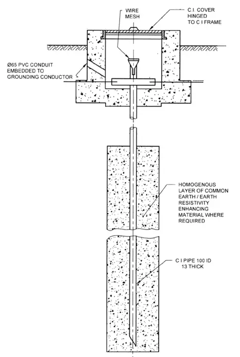
2. Horizontal Plate Electrode
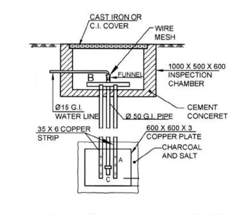
Horizontal Plate Electrode consists of copper or aluminum sheets measuring 0.6 m × 0.6 m × 6 mm thick, buried at 0.6-1 meter depth. Plate electrodes offer better results in areas where vertical drilling is difficult or impossible, such as sites with rock layers that prevent deep driving. The larger surface area compared to rods provides good current distribution. Horizontal plates are effective in building foundations or concrete areas where driving vertical rods is impractical.
3. Ring Electrode
Ring Electrode is a continuous copper conductor loop forming a closed ring around the substation perimeter. This electrode type provides an equipotential surface around the installation and effectively reduces step and touch voltages for personnel safety. Ring electrodes are used in larger installations and mesh systems where multiple equipment items need to be connected to a common reference point.
4. Helical Electrode
Helical Electrode has a spiral-shaped copper rod design that increases surface area in limited space. These electrodes are effective in confined areas where space for multiple rods is unavailable. The helical shape provides more surface contact with soil compared to straight rods of the same length. However, helical electrodes cost more than standard rods and require specialized driving equipment.
5. Chemical Rod
Chemical Rod consists of a metal rod surrounded by a conductive chemical compound that gradually dissolves, maintaining low resistance over years. These specialized rods are useful in dry, high-resistivity regions where maintaining moisture around the electrode is difficult. The compound slowly dissolves and disperses into surrounding soil, enhancing conductivity. Long-term effectiveness depends on the soil’s ability to absorb and retain moisture after the compound dissolves.
Earthing Pit Design and Layout
The earthing pit is the physical location where electrodes are installed and connected. Standard specifications ensure that the pit accommodates sufficient electrodes and maintains resistance targets.
Standard Earthing Pit Specifications:
| Parameter | Typical Value | Notes |
|---|---|---|
| Pit Depth | 1.5 – 2.5 meters | Below frost line; deeper for dry regions |
| Pit Dimensions | 2m × 2m × 2.5m | Depends on number of rods |
| Rod Diameter | 12-16 mm | Copper preferred; mild steel acceptable |
| Rod Length | 2-3 meters | Up to 5 meters in high resistivity soil |
| Rod Spacing | 1-3 × rod length | Prevents mutual resistance reduction |
| Number of Rods | 3-8 rods | Parallel connection for lower resistance |
Pit Construction Process
The pit construction begins with excavation of a rectangular pit 2m × 2m to the required depth. Vertical rods are then driven into the pit bottom using hand driver equipment for manual installation or powered equipment for larger projects. Copper conductors are soldered or crimped to the rod tops using proper connectors that ensure low-resistance contact.
To improve conductivity, the pit is filled with a conductive soil mixture. The typical composition includes 50-100 kg of conductive salt (sodium chloride), 50-100 kg of charcoal powder, and sandy soil mixed with clay. Some installations use commercial earth-enhancing compounds as alternatives.
Backfilling Sequence:
- First 30 cm: Conductive soil mixture (salt + charcoal)
- Next 30 cm: Clay mixed with salt
- Remaining: Normal excavated soil
An access and marking system includes a cast iron cover plate clearly marked with “EARTHING” label. The pit depth and location are properly documented in installation records for future maintenance and testing.
Resistance Reduction Techniques
When calculated earthing resistance exceeds the maximum permissible value for the installation, several techniques can reduce resistance effectively.
- Increasing the number of rods is the most practical approach for most sites. When rods are arranged in parallel configuration (for example, in a rectangular pattern), total resistance decreases. Four rods arranged in a rectangle produce approximately 50% of the resistance of a single rod. Eight rods installed in a 2×4 pattern produce approximately 33% of single rod resistance. This multiplication effect makes adding rods very effective for resistance reduction.
- Increasing rod length accesses deeper soil with better conductivity. Longer rods reach soil layers with lower resistivity and higher moisture content. Resistance decreases logarithmically with length increase, so doubling rod length reduces resistance by approximately 30-40%.
- Increasing electrode surface area through combination methods proves effective in difficult situations. Installations can use multiple types: vertical rods combined with horizontal conductors, installation of ring electrode around perimeter, or use of helical or large-diameter electrodes.
- Chemical treatment of soil reduces natural soil resistivity around electrodes. Conductive salt (NaCl) dissolves in soil moisture and increases ionic conductivity. Charcoal and coke particles improve contact between soil grains. Commercial compounds like Bentonite-based materials absorb and retain moisture long-term. Properly applied chemical treatment can reduce resistivity by 40-60%.
- Increasing soil moisture through irrigation maintains better conductivity year-round. Installing an irrigation system in pit area with automatic watering during dry seasons reduces seasonal resistance variation. Regular watering is particularly beneficial in dry climates. Moisture-dependent installations require ongoing maintenance to remain effective.
A practical example illustrates combination approach: A site with soil resistivity of 500 ohm-meters required earthing resistance of 1 ohm. Single rod calculation showed resistance of 5.2 ohms, clearly insufficient. The solution implemented four rods at 1 meter spacing, which reduced resistance to 2.1 ohms. Chemical treatment with bentonite further reduced resistance to 1.3 ohms. Finally, increasing rod length from 2 meters to 3 meters achieved the target resistance of 0.95 ohms.
Transformer Core Earthing and Tank Earthing
Core Earthing – Single-Point Principle
The transformer core (iron laminations) must be earthed at exactly one point to prevent circulating currents. This single-point earthing principle is fundamental to transformer design and performance.
The core is surrounded by windings and cut by magnetic flux during operation. The changing magnetic field induces voltage between different parts of the core structure. If multiple grounding paths exist from the core to earth, circulating currents flow through the core following the lowest resistance path. These circulating currents cause excessive heating through eddy current losses, increase total iron loss, and can potentially cause core burnout and complete transformer failure.
Why Single-Point Earthing is Essential:
- Prevents circulating currents in core structure
- Eliminates excessive eddy current heating
- Avoids iron loss increase that reduces efficiency
- Prevents potential core burnout and failure
- Maintains transformer cooling characteristics
- Protects core insulation from stress
The single-point earthing method connects one core leg to earth through the core earthing strap. This connection is made at the transformer top through a lead connected to the grounding system. By providing only one path to earth, all induced voltage appears as potential difference between that point and distant earth, preventing current circulation within the core structure itself.
The standard location for core earthing is at the yoke junction where core legs meet, typically the most accessible point. The key principle is that never should multiple points of the core be connected to earth simultaneously, as this creates parallel paths and allows circulating currents to flow.
Tank Earthing – Personnel Safety and Protection
The transformer tank (outer steel structure) must be permanently connected to the earthing system. The tank acts as the primary structural containment and is touched by maintenance personnel during routine inspection and repair.
Purposes of Tank Earthing:
- Ensures safe potential on tank surface for personnel
- Limits hazardous touch voltages during faults
- Provides low-impedance path for external faults
- Protects against static charge accumulation
- Maintains equipotential surfaces around equipment
The connection method involves attaching the main earthing conductor to the tank at the base mounting point where it touches the substation structure. Additional connections at other available points on tank (minimum two connections recommended) provide redundancy and ensure continuous low-resistance connection even if one corrodes or loosens.
The cable lug must be crimped or soldered to the conductor and bolted with lock washer and nut to ensure reliable contact. Proper connection ensures that if any phase conductor accidentally contacts the tank, fault current flows safely to earth. The tank remains at ground potential, making it safe for personnel. Without proper tank earthing, the tank could rise to dangerous potential during a fault, creating severe shock hazard.
Earthing Conductor Selection and Installation
Conductor Material and Size
Material selection depends on cost, durability, and environmental conditions at the site:
- Copper (Preferred): High conductivity, corrosion-resistant, excellent long-term performance
- Aluminum: Lighter, economical, requires corrosion protection
- Steel with Copper Coating: Cost-effective, adequate for protection circuits
- Galvanized Steel: Acceptable but lower conductivity than copper
For transformer neutral earthing, the conductor cross-section selection follows guidelines based on transformer rating:
| Transformer Rating | Recommended Cable Size |
|---|---|
| Up to 100 kVA | 25 mm² |
| 100 – 500 kVA | 50 mm² |
| 500 kVA – 2 MVA | 70-95 mm² |
| 2 MVA and above | 120-150 mm² |
The cable must carry expected fault current without overheating for the duration of protection relay operation, typically 0.5-1 second.
The conductor current capacity is determined using:
\(I = K × A^{0.5}\)
Where \(I\) is permissible current in amperes, \(A\) is conductor cross-section in mm², and \(K\) is the material constant (226 for copper, 148 for aluminum).
Installation Requirements
Routing and Protection:
- Single, continuous run from transformer neutral to earthing pit
- Avoid sharp bends (maintain radius ≥ 5 × conductor diameter)
- Protected from mechanical damage through conduit or cable tray
- Kept away from hot surfaces that could damage insulation
Connection Methods:
- Crimped or soldered terminals at both ends
- Bolted connections with lock washers
- Proper contact pressure (finger-tight plus ¼ turn)
- Weatherproof covers at joints
Burial of earthing conductors should be minimum 600 mm below surface in cultivated areas and deeper in agricultural areas to prevent accidental damage during plowing. Buried cables should be marked with warning tape placed 300 mm above the cable to alert excavation work. In corrosive environments, cables need conduit protection. PVC ducting in wet areas prevents water ingress. All connections remain accessible for future testing and maintenance.
Maintenance and Testing of Earthing Systems
Regular Inspection Schedule
Yearly Inspection:
- Visual inspection of external connections for proper installation
- Checking for corrosion on terminals and bolts
- Verification of no loose connections present
- Inspection of earthing cable for visible damage
- Verification that pit cover is secure and properly marked
- Check for surface condition around pit area
Every 2-3 Years:
- Detailed measurement of earthing resistance using tester
- Comparison with baseline values established at installation
- Removal of vegetation or debris over pit
- Internal connection inspection if pit is accessible
- Assessment of soil condition around electrodes
Every 5 Years:
- Detailed pit inspection if feasible (may require excavation)
- Rod condition assessment for corrosion or damage
- Evaluation of conductive compound effectiveness
- Professional survey of soil resistivity changes
- Assessment of need for treatment renewal
Testing Methods and Equipment
The fall-of-potential method provides the most accurate earth resistance measurements. The test clamp is connected to the earthing electrode at the pit. A potential electrode is placed at distance greater than 20 meters to measure voltage. A current electrode is placed at distance greater than 40 meters. The digital earth tester measures resistance by injecting AC current and measuring resulting voltage. Ideally, three measurements are taken at different angles and averaged to account for soil non-uniformity.
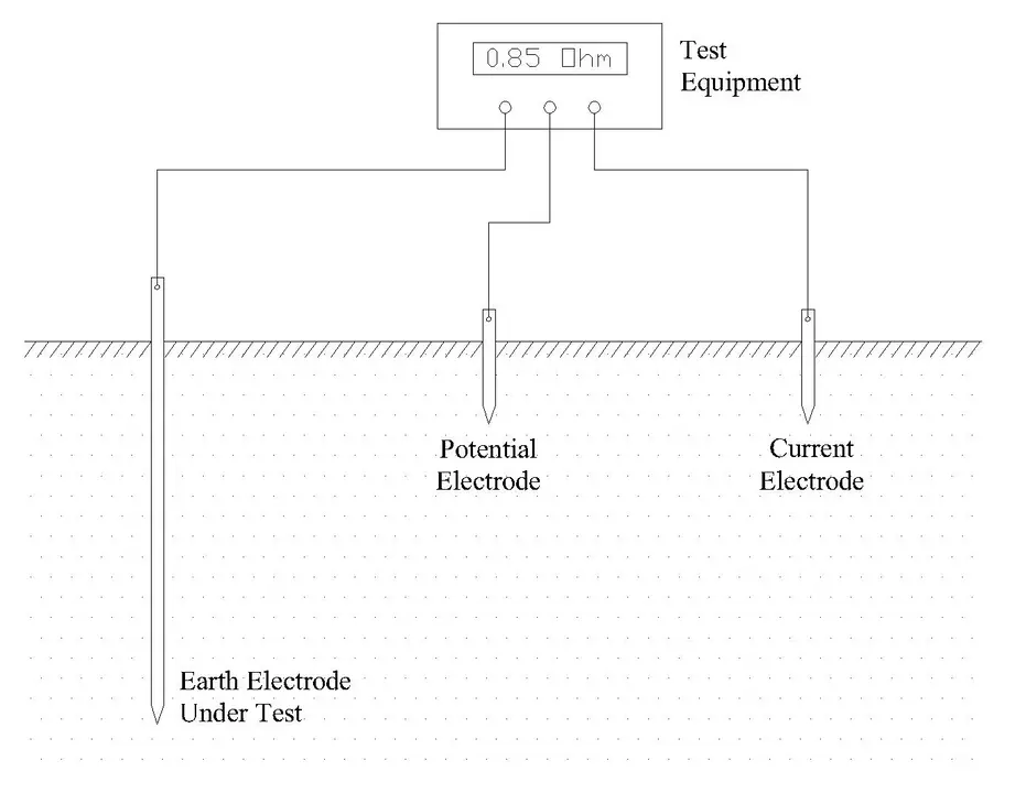
Fall-of-Potential Testing Process:
- Connect test clamp to earthing electrode at pit
- Place potential electrode at distance ≥ 20 meters
- Place current electrode at distance ≥ 40 meters
- Digital tester injects current and measures voltage
- Calculate resistance from V/I ratio
- Take three measurements at different angles
- Average results for accuracy
Digital earth testers offer the modern approach to measurement. They automatically compensate for soil resistivity variations and provide instant measurement without manual calculations. These devices are suitable for ongoing monitoring of earthing system performance.
Expected Results:
| System Component | Acceptable Resistance | Remark |
|---|---|---|
| Power Transformer Neutral | < 1.0 Ω | Critical – highest priority |
| Transformer Tank | < 2.0 Ω | Should be < 0.5 Ω ideally |
| Lightning Arrester | < 5.0 Ω | Transient suppression |
| Complete Substation | < 0.5 Ω | Mesh design targets |
Standards and Codes for Transformer Earthing
International Standards
IEC 60071-2: High-Voltage Alternating Current Equipment – Insulation Coordination – Application Guidelines defines overvoltage limits and specifies protection requirements. It provides guidance on earthing system design to protect equipment insulation.
IEC 60364: Low-Voltage Electrical Installations specifies requirements for earthing conductor sizing and connection specifications. It establishes testing procedures for verification of earthing system performance.
IEEE 142: IEEE Recommended Practice for Grounding of Industrial and Commercial Power Systems offers comprehensive grounding design guidance based on North American practice. It includes resistance calculation methods and system design recommendations for various applications.
IEEE 80: IEEE Guide for Safety in AC Substation Grounding provides guidance on step and touch voltage calculations and safety limits for personnel protection. It covers grounding electrode design in detail.
Indian Standards
IS 3043: Code of Practice for Earthing is the primary standard for earthing system design in India. It establishes:
- Earthing system design principles
- Recommended resistance values by equipment type
- Installation specifications
- Testing and maintenance procedures
IS 4651: Lightning Conductors – Code of Practice combines requirements for lightning and fault earthing protection. It defines:
- Design safety factors
- Material specifications
- Combined protection requirements
IE(I) Standards: Institution of Engineers provides additional guidance along with State Electricity Board specifications that may vary by region.
Practical Examples and Case Studies
Case Study 1: Urban Distribution Substation (22 kV/400 V)
An urban distribution substation in alluvial soil with clay composition had soil resistivity of 150 ohm-meters. The installation included one 2 MVA transformer and distribution panel serving a residential area. The maximum permissible earthing resistance was 1.0 ohm for the power transformer.
Calculations indicated that a single rod would achieve resistance of 2.1 ohms, clearly exceeding the target. A four-rod electrode system was designed with 1.5 meter spacing. Estimated resistance after installation was 1.0 ohm.
Installation Details:
- Four vertical copper rods: 16 mm diameter, 2.5 meter length
- Arrangement: Square pattern
- Pit dimensions: 2m × 2m × 2.5m
- Conductive treatment: 75 kg salt + 60 kg charcoal
- Neutral conductor: 70 mm² copper cable
After installation, measured resistance was 0.98 ohms, achieving the design target. With a 100 ohm NGR installed, the fault current at 22 kV would be 127 amperes. The Ground Potential Rise for a 2 second fault would be approximately 98 volts, which is acceptable. The system has been operational since 2015 with stable performance and no resistance degradation.
Case Study 2: High Resistivity Rural Substation
A rural substation in a hilly region with sandy loam soil and rock patches faced very high soil resistivity of 800 ohm-meters. The area had limited access and difficult terrain. Standard electrode design would require single rod resistance of 18 ohms, making single electrode approach completely infeasible. Target resistance was less than 1 ohm.
The design challenge was that conventional methods could not achieve required resistance. Hard rock prevented deep drilling.
Solution Implemented:
- Three horizontal copper plate electrodes (0.5 m² each)
- Radial conductor network extending 15 meters outward
- Specialized bentonite-based treatment: 100 kg
- Seasonal irrigation with surface drip system
The installation achieved final resistance of 1.2 ohms, slightly above the target but acceptable with appropriate NGR selection of 110 ohms. Annual maintenance was required for the irrigation system. Resistance variation between dry and wet seasons was limited to ±0.3 ohms due to moisture management. The system has functioned satisfactorily for 8+ years.
Case Study 3: Industrial Substation with High Fault Current
An industrial substation with three 10 MVA transformers at 33 kV voltage had very low fault impedance requiring very high fault current. The installation was adjacent to manufacturing facility with limited available space (30m × 40m area). Multiple loads within the facility required the same earth reference point. The requirement was very low earthing resistance below 0.5 ohms.
The design approach used substation mesh design with specialized components:
Mesh Design Features:
- Perimeter ring electrode: 100mm × 100mm copper angle
- Crossover conductors: 70 mm² copper at 5 meter intervals
- Central core area: Eight vertical rods (3 meter length) + two horizontal mats
- Conductive enhancement: 500 kg bentonite-based compound
The installation achieved resistance of 0.38 ohms, meeting the design target. Ground Potential Rise for a 20 kA fault would be 7.6 kV, which required surge arresters for equipment protection. Touch voltage was 280 volts, safe with proper precautions and warning signs. All IEEE 80 safety criteria were satisfied.
Key Formulas and Calculations
Earthing Resistance (Single Vertical Rod)
Dwight’s formula calculates earthing resistance of a single vertical rod:
\(R = \frac{\rho}{2\pi L} \left[ \ln\left(\frac{4L}{d}\right) – 1 \right]\)
Where R is earthing resistance in ohms, ρ is soil resistivity in ohm-meters, L is rod length in meters, and d is rod diameter in meters.
For example, with soil resistivity of 200 ohm-meters, rod length of 2.5 meters, and diameter of 0.016 meters:
\(R = \frac{200}{2\pi × 2.5} \left[ \ln\left(\frac{4×2.5}{0.016}\right) – 1 \right]\)
\(R = \frac{200}{15.71} \left[ \ln(625) – 1 \right]\)
\(R = 12.74 × [6.44 – 1]\)
\(R = 12.74 × 5.44 = 69.3 \text{ Ω (single rod)}\)
This calculation shows that a single rod in 200 ohm-meter soil achieves 69.3 ohms resistance.
Parallel Rods Resistance Reduction
When identical rods are arranged in parallel configuration, total resistance reduces approximately as:
\(R_n = \frac{R_1}{n × 0.7}\)
Where \((R_n)\) is the resistance of n parallel rods and \((R_1)\) is single rod resistance. For four rods of 69.3 ohms each:
\(R_4 = \frac{69.3}{4 × 0.7} = \frac{69.3}{2.8} = 24.8 \text{ Ω}\)
Neutral Grounding Resistor Calculation
The required NGR resistance is calculated from:
\(R_{NGR} = \frac{V_{phase}}{I_{desired}}\)
For a 33 kV system with desired fault current of 300 amperes, the phase voltage is:
\(V_{phase} = \frac{33,000}{\sqrt{3}} = 19,050 V\)
The required NGR is:
\(R_{NGR} = \frac{19,050}{300} = 63.5 \text{ Ω}\)
Ground Potential Rise (GPR)
Ground Potential Rise is calculated simply as:
\(V_{GPR} = I_{fault} × R_{earth}\)
For safety, the GPR should not exceed the touch voltage limit calculated as:
\(V_{touch} = (1000 + 6 × \rho) / t\)
Where ρ is soil resistivity and t is fault duration in seconds.
Conclusion
Transformer earthing is not merely a technical requirement—it is a fundamental responsibility toward system reliability, equipment longevity, and personnel safety. Proper design and maintenance of the earthing system ensures that when faults occur, they are detected and cleared rapidly without endangering human life or destroying expensive equipment.
The selection of appropriate earthing method depends on multiple factors: system voltage, fault current expectations, continuity requirements, soil conditions, and regulatory standards. Resistance earthing has emerged as the most popular method for medium voltage systems globally due to its excellent balance between equipment protection and operational effectiveness.
Regular maintenance and periodic testing of the earthing system are equally important as initial design. An earthing system that was effective at installation may degrade over time due to soil moisture changes, electrode corrosion, or settlement. Yearly inspections and testing at 3-5 year intervals ensure the system continues to provide the protection it was designed to deliver.