Every transformer installed in a power system has an inherent opposition to current flow, known as transformer impedance. This single parameter affects how a transformer regulates voltage, how much fault current it allows during short circuits, how it shares load with other transformers in parallel, and how efficiently it delivers power to connected loads.
Engineers who design substations, select protective equipment, or coordinate relay settings must know the impedance value of each transformer in the network. Without accurate impedance data, fault calculations become unreliable, protection schemes may fail to operate correctly, and transformers connected in parallel may share load unevenly.
In this technical guide, we will discuss everything you need to know about transformer impedance, including its definition, components, measurement through short-circuit testing, effects on voltage regulation and fault currents, parallel operation requirements, zero-sequence behavior, and protection applications. Practical examples are included throughout to help you apply these concepts in real-world scenarios confidently.
1. What is Transformer Impedance?
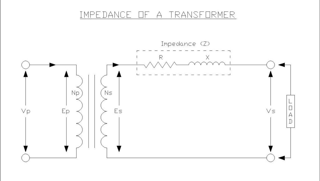
Transformer impedance is the total opposition that a transformer offers to alternating current flow through its windings. Unlike a simple resistance, transformer impedance is a complex quantity comprising both resistive and reactive components, mathematically expressed as the vector sum of winding resistance and leakage reactance.
In practical transformers, both the primary and secondary windings possess finite resistance due to the copper or aluminum conductors used in their construction. Additionally, not all magnetic flux generated by one winding successfully links with the other winding. Some flux “leaks” through paths outside the magnetic core, creating leakage reactance. This leakage flux is inherent to transformer operation.
When an AC voltage is applied to a transformer’s primary winding, the impedance opposes current flow, resulting in a voltage drop across the windings. The magnitude of this voltage drop directly correlates with the transformer’s impedance value, making it an important parameter for predicting transformer performance under various loading conditions.
2. What is Percentage Impedance?
The percentage impedance (also called impedance voltage) is the most practical way to express transformer impedance, as it appears on every transformer nameplate. Percentage impedance is defined as the percentage of rated voltage required to circulate rated full-load current through one winding when the other winding is short-circuited at rated frequency.
For example, consider a transformer with a 5% impedance rating and a primary voltage of 11,000V. When the secondary winding is short-circuited, applying just 5% of the rated voltage (550V) to the primary winding will cause rated full-load current to flow through both windings. Conversely, if the full 11,000V were applied under short-circuit conditions, the current would reach approximately 20 times the rated current (100% ÷ 5% = 20).
The mathematical definition of percentage impedance is given by:
\( \%Z = \left( \dfrac{V_{sc}}{V_{rated}} \right) \times 100 \)
where \(V_{sc}\) is the voltage applied during the short-circuit test that produces rated current, and \(V_{rated}\) is the transformer’s rated primary voltage.
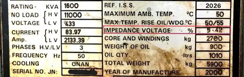
The above nameplate of a 1.6 MVA Transformer shows the percentage impedance as 5.42%.
3. Components of Transformer Impedance
Transformer impedance consists of two fundamental components that contribute to the total opposition to current flow:
3.1 Winding Resistance
Winding Resistance is the resistance component results from the physical resistance of the copper or aluminum conductors used in both primary and secondary windings. This resistance causes \(I^2 R\) losses (copper losses) during operation, which appear as heat dissipation and reduce transformer efficiency. The total equivalent resistance referred to either the primary or secondary side is the sum of both winding resistances, appropriately transformed by the turns ratio.
Winding resistance does not remain constant, it changes with temperature. As the transformer carries load, conductor temperature rises and the resistance increases proportionally. Standard practice requires correcting measured resistance values to a reference temperature of 75°C (for transformers with Class A insulation) or 85°C (for Class F insulation) so that test results from different ambient conditions can be compared on the same basis. This correction follows the formula:
\(R_{corrected}=R_{measured} \times \dfrac{T_{ref}+C}{T_{measured} + C}\)
where \(C\) is 234.5 for copper conductors and 225 for aluminum conductors. Factory acceptance test reports always include temperature-corrected impedance values for this reason.
3.2 Leakage Reactance
The reactance component arises from leakage flux, the portion of magnetic flux that links only one winding rather than both. In an ideal transformer, all flux generated by the primary winding would pass through the core and link perfectly with the secondary winding. In reality, some flux takes alternative paths through air, insulating oil, and structural materials.
This leakage flux induces self-reactance in each winding, represented as leakage reactance in the equivalent circuit. The leakage reactance depends on several design factors including winding geometry, spacing between windings, number of turns, core window size, and insulation thickness.
The total impedance is the vector sum of resistance and reactance:
\(Z_{eq}=\sqrt{R_{eq}^2+X_{eq}^2}\)
where, \(R_{eq}\) is the equivalent resistance and \(X_{eq}\) is the equivalent leakage reactance, both referred to the same side of the transformer.

4. Impedance Values and Standards
Transformer impedance values are not arbitrary, they follow well-established standards and typical ranges based on transformer size, voltage class, and application. International standards including IEEE C57.12.34, IEC 60076, and CSA C227.4 specify recommended impedance ranges for different transformer ratings.
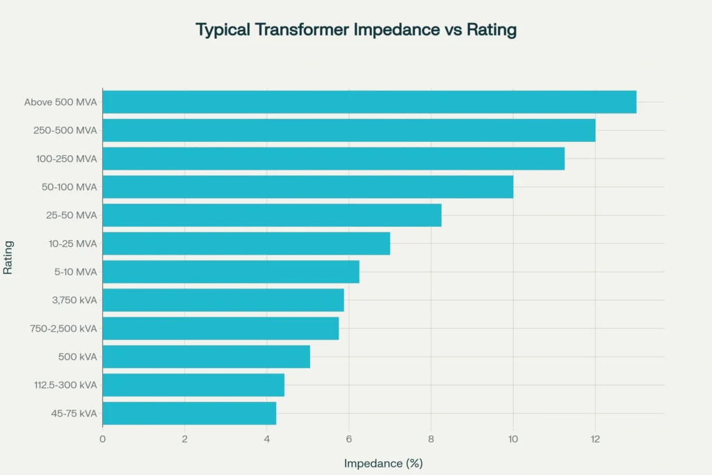
Distribution transformers (below 1 MVA) have impedance values that range from 4% to 6%. These relatively low impedance values help minimize voltage drops during normal operation and provides better voltage regulation for consumers. As transformer capacity increases, so does the impedance percentage. Medium power transformers (1-10 MVA) generally have impedances between 5.75% and 7.5%.
Large power transformers used in transmission networks exhibit even higher impedance values. Substation transformers in the 10-100 MVA range have impedances from 7% to 11%, while extra-high voltage (EHV) transmission transformers above 100 MVA commonly have impedances ranging from 10% to 14%. This progressive increase serves a protective function. It limits the massive fault currents that could otherwise flow in high-capacity systems.
Standards allow a tolerance of ±7.5% to ±10% from the specified impedance value after manufacturing. For instance, a 33 MVA, 132/6.6 kV transformer with a specified 13% impedance and a ±7.5% manufacturing tolerance should measure between 12.025% and 13.975% during factory acceptance testing.
5. Measurement of Transformer Impedance: The Short-Circuit Test
The short-circuit test (also called the impedance test or load loss test) is the standard method for determining a transformer’s impedance. This carefully controlled procedure measures impedance without risking transformer damage from excessive current.
5.1 Short-Circuit Test Procedure
- Short-circuit the low-voltage (LV) winding using a low-resistance conductor
- Apply voltage to the high-voltage (HV) winding starting from zero, using a variable voltage source (variac)
- Gradually increase the applied voltage while monitoring the current
- Record readings when the current reaches the rated full-load value
- Measure and document the applied voltage, current, and power consumption at this operating point
The test is performed from the HV side with the LV side short-circuited for two practical reasons: the HV side requires lower test currents (making measurement easier), and the reduced voltage levels on the HV side make the test safer to conduct. Because the applied voltage is only a small percentage of rated voltage (usually 4-15%), core losses remain negligible. The measured power therefore equals the copper losses at full load almost entirely.
The voltage required to circulate rated current under these short-circuit conditions is the impedance voltage. Expressing this voltage as a percentage of the rated voltage directly gives the percentage impedance.

5.2 Calculations and Parameters
From the short-circuit test measurements, several parameters can be determined:
Equivalent impedance:
\( Z_{01} = \dfrac{V_{sc}}{I_{rated}} \)
Equivalent resistance (from wattmeter reading):
\( R_{01} = \dfrac{W_{sc}}{I_{rated}^2} \)
Equivalent reactance:
\( X_{01} = \sqrt{Z_{01}^2 – R_{01}^2} \)
where, \(W_{sc}\) is the power measured during the short-circuit test, primarily consisting of copper losses at full load.
5.3 Worked Example: Short-Circuit Test Calculation
A 500 kVA, 11,000/415V three-phase transformer undergoes a short-circuit test from the HV side with the following readings:
- Applied voltage \((V_{sc}): 550V\)
- Current \((I_{rated}): 26.24A\) (rated HV current)
- Power \((W_{sc}): 4,200W\)
Step 1: Percentage impedance
\(\%Z=\dfrac{550}{11,000}\times 100=5\%\)
Step 2: Equivalent impedance referred to the HV side
\(Z_{01}=\dfrac{550}{26.24}=20.96\Omega\)
Step 3: Equivalent resistance
\(R_{01}=\dfrac{4200}{26.24^2}=6.10\Omega\)
Step 4: Equivalent reactance
\(X_{01}=\sqrt{20.96^2−6.10^2}=20.05\Omega\)
This tells us the transformer’s impedance is dominated by leakage reactance rather than winding resistance, which is the case for most power transformers above 100 kVA.
6. The Role of Impedance in Transformer Performance
6.1 Voltage Regulation
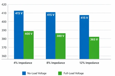
Voltage regulation describes how transformer secondary voltage changes between no-load and full-load conditions for a constant primary voltage. Impedance directly determines voltage regulation. Higher impedance produces greater voltage drops under load, resulting in poorer regulation.
The voltage regulation can be calculated using following formula for lagging power factor loads:
\( \text{% Regulation} \approx \dfrac{I_S(R\cos\phi + X\sin\phi)}{V_{2(rated)}} \times 100\% \)
For leading (capacitive) power factor loads, the sign before the reactance term changes to negative:
\( \text{% Regulation} \approx \dfrac{I_S(R\cos\phi – X\sin\phi)}{V_{2(rated)}} \times 100\% \)
where, \(I_s\) is the secondary current, \(R\) and \(X\) are the equivalent resistance and reactance referred to the secondary side, \(\phi\) is the power factor angle and \(V_{2(rated)}\) is the rated secondary voltage.
6.2 Short-Circuit Current Limitation
One of the most important protective functions of transformer impedance is limiting fault currents during short-circuit conditions. When a fault occurs on the secondary side, the transformer’s impedance restricts the magnitude of fault current that can flow.
The short-circuit current can be approximated by:
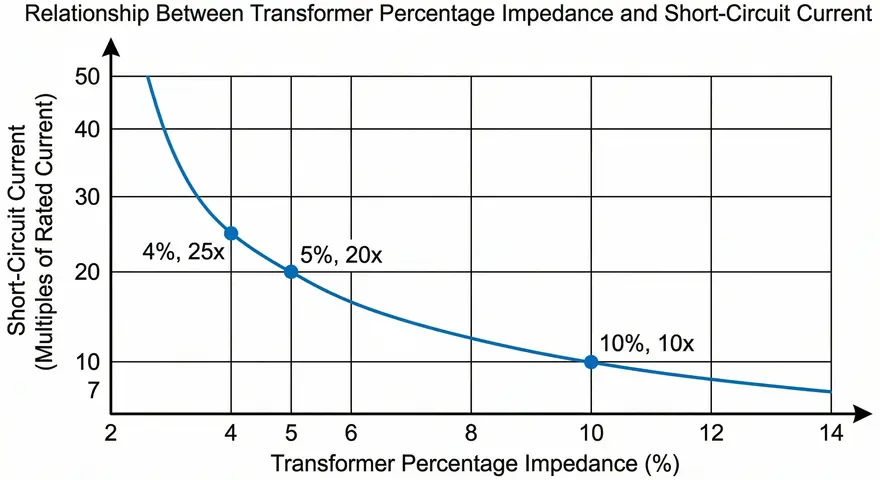
\( I_{sc} = \dfrac{I_{rated} \times 100}{\%Z} \)
A transformer with 5% impedance will produce a short-circuit current approximately 20 times its rated current, while a 10% impedance transformer limits this to 10 times rated current. Higher impedance transformers provide better protection against short-circuit damage but at the cost of increased voltage drop during normal operation. This protective characteristic becomes increasingly important in high-capacity systems where fault currents can reach destructive levels.
Example: A 1000 kVA, 11kV/415V transformer with 6% impedance has a rated secondary current of:
\(I_{rated}=\dfrac{1000\times 1000}{\sqrt{3}\times 415}=1391A\)
The maximum short-circuit current available at the secondary terminals is:
\(I_{sc}=\dfrac{1391\times 100}{6}=23,183A\)
All downstream circuit breakers, busbars, and cables must be rated to withstand this fault current level. If the transformer had 8% impedance instead, the fault current would drop to 17,388A — a 25% reduction that could allow smaller and less expensive switchgear to be used.
6.3 System Efficiency
Transformer impedance affects system efficiency through the voltage drops and losses it creates. The resistive component causes direct power loss proportional to the square of the load current, while the reactive component causes the voltage drop and power delivery to the load.
Lower impedance transformers generally provide better efficiency under normal loading conditions because they produce smaller voltage drops and allow more effective power transfer to the load. However, this advantage must be weighed against the increased short-circuit current stress and the need for more robust downstream equipment capable of withstanding higher fault levels.
7. High Impedance vs. Low Impedance Transformers
7.1 High Impedance Transformers
Advantages:
- Superior short-circuit protection through effective fault current limitation
- Reduced stress on system insulation and equipment during faults
- Better suited for stiff power systems with high available fault currents
- Enhanced protection against poor power factor conditions
Disadvantages:
- Increased voltage drop under load, resulting in poorer voltage regulation
- Higher voltage required to produce full-load current
- Reduced efficiency due to greater impedance losses
- Risk of voltage instability in weak systems
High impedance transformers find application in situations where limiting fault currents is paramount, such as industrial facilities with extensive downstream equipment or systems where existing switchgear has limited breaking capacity.
7.2 Low Impedance Transformers
Advantages:
- Excellent voltage regulation with minimal voltage drop under varying loads
- Higher efficiency during normal operation
- Better performance in weak systems or at the remote ends of long distribution lines
- Improved ability to start large motors without excessive voltage sag
Disadvantages:
- Higher short-circuit currents requiring more robust and expensive protective equipment
- Increased stress on transformer insulation during fault conditions
- Greater risk of damage during short-circuit events
Low impedance transformers (in the range of 2-4%) are often specified for distribution systems serving remote loads where voltage regulation matters most, or where the system impedance is already high enough to naturally limit fault currents.
8. Parallel Operation and Impedance Matching
Parallel operation of transformers provides various advantages including load sharing, improved efficiency, redundancy, and flexible capacity management.
8.1 Requirements for Parallel Operation
For transformers to share load properly when operated in parallel, several conditions must be satisfied:
- Identical voltage ratios to prevent circulating currents under no-load conditions
- Same percentage impedance on their respective MVA ratings
- Identical impedance angle (X/R ratio) to ensure proper real and reactive power sharing
- Same phase displacement and vector group
- Matched polarity across all terminals
8.2 Impact of Impedance Mismatch
The percentage impedance requirement is particularly important. Load sharing between paralleled transformers is inversely proportional to their impedances. When transformers with different percentage impedances operate in parallel, the transformer with lower impedance carries a disproportionately higher share of the total load.
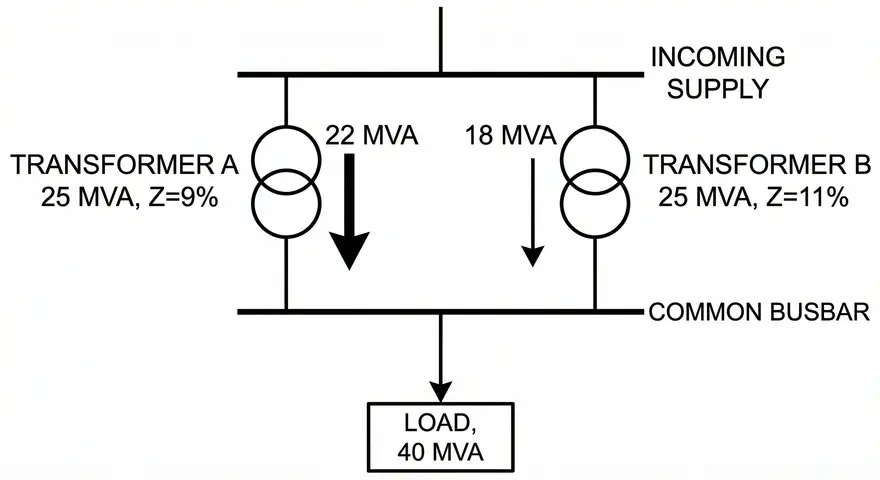
Consider two 25 MVA transformers connected in parallel, one with 9% impedance and the other with 11% impedance. The total load is 40 MVA at unity power factor.
Load sharing is inversely proportional to impedance:
- Transformer 1 (9%): Share \(=\dfrac{\frac{1}{9}}{\frac{1}{9}+\frac{1}{11}}=\dfrac{11}{20} = 55\%\) of 40 MVA = 22 MVA (88% of its 25 MVA rating)
- Transformer 2 (11%): Share \(=\dfrac{\frac{1}{11}}{\frac{1}{9}+\frac{1}{11}}=\dfrac{9}{20} = 45\%\) of 40 MVA = 18 MVA (72% of its 25 MVA rating)
The 9% unit is loaded to 88% of its capacity while the 11% unit is loaded to only 72%. This unequal sharing prevents full utilization of installed capacity and may overload the lower-impedance unit if the total load increases further.
For satisfactory parallel operation, circulating current should not exceed 10% of the full-load rated current of the smaller unit. Standards allow impedance tolerances of ±7.5% to ±10%, meaning transformers with nominally identical impedances may still exhibit slight differences that affect load sharing.
8.3 Parallel Operation Benefits and Challenges
When properly matched, paralleled transformers offer majorbenefits:
- Load sharing proportional to transformer ratings
- Improved overall efficiency by optimizing loading across units
- Redundancy for maintenance and emergency conditions
- Flexible capacity expansion without replacing existing equipment
However, parallel operation also introduces challenges:
- Increased system fault levels due to reduced combined impedance
- Higher circuit breaker and bus ratings required
- Complex protection coordination requirements
- Sensitivity to tap changer position mismatches
8.4 Effect of Tap Changer Position on Parallel Operation
Transformers equipped with on-load tap changers (OLTCs) require special attention during parallel operation. Each tap position changes the transformer’s effective voltage ratio, and a mismatch between tap positions of paralleled units creates a voltage difference that drives circulating current between the transformers. This circulating current adds to the load current in one unit and subtracts from it in the other, producing uneven loading and additional losses even at no-load conditions.
Most modern OLTC controllers include a parallel operation mode that coordinates tap changes across multiple units. Master-follower schemes, circulating current minimization methods, and power factor–based control algorithms are commonly used to keep tap positions matched within one step of each other.
The impedance of a transformer also varies slightly with tap position. At extreme tap positions, the effective impedance can differ by several percent from the nominal value. This variation must be accounted for in parallel operation studies and protection coordination.
9. Transformer Impedance in Power System Protection
Transformer impedance plays a direct role in power system protection schemes, influencing both fault level calculations and protection device coordination.
9.1 Fault Level Calculations
Accurate knowledge of transformer impedance is necessary for calculating available fault currents at various points in the power system. The transformer impedance forms part of the total system impedance that limits fault current magnitude.
For a standard fault calculation using the infinite bus assumption (where the source impedance is assumed to be zero), the maximum fault current on the secondary side is:
\(I_{fault}=\dfrac{I_{rated} \times 100}{\%Z}\)
In real systems, the source impedance is not zero. The actual fault current is lower than the infinite bus value because the upstream network impedance adds to the transformer impedance. Utility fault level data at the primary terminals is therefore needed for accurate calculations.
9.2 Protection Schemes
Several protection schemes rely on transformer impedance characteristics:
Differential protection compares currents entering and leaving the transformer, accounting for the impedance and turns ratio to detect internal faults. The impedance influences the sensitivity settings and restraint characteristics of differential relays.
Restricted earth fault protection provides sensitive ground fault detection for grounded wye-connected windings, with settings influenced by the transformer’s zero-sequence impedance. This impedance differs from positive-sequence impedance and depends on core construction and winding connections.
Distance protection for transformer-feeder arrangements uses impedance measurement principles, with the protection zone set to reach partway into the transformer impedance. Proper zone setting requires accurate impedance data to ensure adequate protection coverage without unwanted operations.
Overcurrent protection settings must account for transformer impedance to coordinate properly with upstream and downstream devices while providing adequate sensitivity for internal faults. The impedance determines the magnitude of fault current available to operate protective relays.
10. Zero-Sequence Impedance
Zero-sequence impedance is a specialized parameter used for analyzing unbalanced faults, particularly line-to-ground faults. Unlike positive- and negative-sequence impedances which are usually equal, zero-sequence impedance can differ greatly depending on transformer winding connections and core construction.
10.1 Measurement and Significance
Zero-sequence impedance is measured using a single-phase test where all three phase terminals are connected together and energized relative to a neutral point. The voltage is increased until rated current flows, similar to the positive-sequence short-circuit test.
For grounded wye-grounded wye transformers with three-limb core construction, zero-sequence flux must find return paths through tank walls, oil, and air rather than through the core iron. This results in complex zero-sequence behavior requiring multiple tests to characterize fully. Four separate tests may be necessary to determine all parameters of the equivalent T-model used for system studies.
The zero-sequence impedance strongly influences ground fault current magnitudes and the effectiveness of ground fault protection schemes. Accurate zero-sequence data is required for protective relay settings, particularly for restricted earth fault and differential protection.
10.2 Transformer Connection Effects
Zero-sequence impedance behavior varies with winding connections as follows:
- Delta windings provide a closed path for zero-sequence currents, trapping them and preventing propagation to other windings
- Ungrounded wye windings offer infinite zero-sequence impedance as no path exists for zero-sequence current flow
- Grounded wye windings allow zero-sequence current flow, with impedance depending on grounding method and core design
- Three-limb cores tend to show lower zero-sequence impedance than five-limb cores due to magnetic flux paths
11. Transformer Impedance Calculator
Transformer Impedance Calculator
Calculate impedance, fault current, and percentage impedance with precision
Formula: Z = V / I
Calculate impedance from voltage and current values
Educational tool for electrical engineering calculations. Always verify results with professional standards.
12. Quiz on Transformer Impedance
Transformer Impedance Quiz
Test your knowledge of transformer impedance concepts and calculations
Ready to Test Your Knowledge?
This comprehensive quiz covers transformer impedance concepts from basic fundamentals to advanced applications used in electrical engineering.
Based on your performance, here are some areas to focus on:
13. Conclusion
Transformer impedance is a foundational parameter that directly affects power system design, operation, and protection. This complex quantity made up of winding resistance and leakage reactance governs voltage regulation, limits fault currents, determines load sharing during parallel operation, and influences overall system efficiency.
A transformer with high impedance offers better fault current limitation but suffers from poorer voltage regulation. A low impedance transformer delivers excellent regulation but exposes downstream equipment to higher fault stresses. Selecting the right impedance value requires balancing these competing requirements for each specific application.
14. Frequently Asked Questions (FAQs)
The “right” percentage impedance depends on the transformer’s application. Distribution transformers below 1 MVA generally have 4% to 6% impedance to minimize voltage drop for end consumers. Power transformers in the 10-100 MVA range have 7% to 11% impedance to limit fault currents at substation levels. EHV transmission transformers above 100 MVA may have 10% to 14% impedance. There is no single “best” value, the choice involves a trade-off between voltage regulation and fault current limitation.
A transformer with excessively high impedance produces a large voltage drop under load, leading to poor voltage regulation at the secondary terminals.
Low impedance allows very high fault currents to flow during short-circuit conditions. This can overstress the transformer windings mechanically and thermally, damage downstream switchgear, and create safety hazards.
Yes, but they will not share load equally. The transformer with lower impedance will carry a proportionally larger share of the total load. If the impedance difference is too large, the lower-impedance transformer may become overloaded before the combined rated capacity is reached.
The short-circuit test applies only a small fraction of rated voltage (equal to the percentage impedance) to circulate full-load current. At this low voltage level, the core flux is very small, making core losses negligible. The test therefore isolates the winding impedance from core characteristics and provides an accurate measurement of both copper losses and leakage reactance.
The impedance itself (in ohms or as a percentage) is a fixed design characteristic that does not change with load.
Positive-sequence impedance governs transformer behavior under balanced three-phase conditions and during three-phase faults. Zero-sequence impedance governs behavior during unbalanced faults involving ground, such as single line-to-ground faults.
Changing the tap position alters the number of active turns in the tapped winding, which changes both the voltage ratio and the leakage reactance. At extreme tap positions, the impedance can vary by several percent from the nominal nameplate value.
Larger transformers are connected to systems with higher available fault currents. Higher percentage impedance limits these fault currents to levels that the transformer windings and connected equipment can safely withstand.
No. Transformer impedance is the impedance of the transformer alone. Source impedance includes the impedance of the entire upstream network — generators, transmission lines, other transformers, and the utility supply — as seen from a particular point in the system.