Every electrical system relies on insulation to keep current flowing safely through its intended path. Over time, insulation breaks down due to moisture, heat, chemical exposure, mechanical wear, and aging. If left unchecked, this degradation leads to short circuits, equipment failure, arc flash hazards, and even fires. A Megger formally called an insulation resistance tester is the go-to instrument used by electrical engineers, maintenance technicians, and industrial electricians worldwide to evaluate the health of electrical insulation.
In this technical guide, we will discuss everything you need to know about Megger testing, including its working principle, types of Megger instruments, test voltage selection, step-by-step testing procedure, temperature correction, guard terminal usage, result interpretation, relevant industry standards (IEEE 43, ANSI/NETA ATS, IEC 60364-6), and best practices for maintaining accurate records. Practical examples are included throughout to help you apply these concepts in real-world scenarios confidently.
1. What Is a Megger?
A Megger is a portable electrical testing instrument designed to measure the insulation resistance of electrical cables, motors, transformers, generators, and other electrical equipment. The device generates a high DC voltage from 250V to 15kV depending on the model, applies it to the insulation, and measures how much current leaks through.
The term “Megger” actually originated as a brand name from the company Megger Group Limited, but it has become so widely used that it now serves as a generic term for any insulation resistance tester. The test is named after the Megger brand, which pioneered insulation testing instruments in the early 20th century.

Think of a Megger as a doctor’s stethoscope for electrical systems. Just as a doctor uses a stethoscope to listen for abnormalities in your heartbeat, an electrician uses a Megger to detect weaknesses in insulation that might not be visible to the naked eye. The device applies a high DC voltage to the insulation and measures how much current leaks through it. Healthy insulation will allow very little current to pass, resulting in a high resistance reading measured in megaohms (MΩ)—hence the name “Megger.”
The fundamental purpose of a Megger test is to verify that the insulation between conductors and between conductors and ground is adequate for safe operation. When insulation deteriorates due to moisture, heat, age, chemical exposure, or physical damage, its resistance decreases. The Megger detects these changes allowing maintenance personnel to identify and address problems before they cause equipment failure or safety hazards.
2. How Does a Megger Work? (Working Principle)
The working principle of a Megger is based on Ohm’s Law, which states that voltage equals current multiplied by resistance (V = I × R). By applying a known high voltage across the insulation and measuring the resulting current flow, the Megger calculates the insulation resistance.
Here is a simplified breakdown of the process:
- The Megger generates a high DC voltage (for example, 500V, 1000V, or 5000V).
- This voltage is applied between the conductor and ground (or between two conductors).
- A tiny leakage current flows through the insulation.
- The instrument measures this current and uses Ohm’s Law (R = V / I) to calculate the insulation resistance.
- The result is displayed in megaohms (MΩ) or gigaohms (GΩ).
The Megger measures this current and calculates the insulation resistance. Higher insulation resistance values indicate more effective insulation. When electrical insulation is in good condition, the current flow is minimal and the Megger pointer moves toward infinity (∞). Conversely, if there is a short circuit or severe insulation breakdown, the pointer indicates zero.
To understand this better, let’s use a simple analogy. Imagine you’re trying to measure how waterproof a raincoat is. You spray water at it with a certain pressure (voltage) and measure how much water seeps through (current). A good raincoat will let very little water through, indicating high resistance to water penetration. Similarly, good electrical insulation will let very little current through when voltage is applied, indicating high insulation resistance.
3. Three Components of Leakage Current
The total current that flows during a Megger test is not one simple stream. It is made up of three distinct components, and recognizing them will help you take better readings.
3.1 Capacitive Charging Current
The insulation between a conductor and ground behaves like a capacitor. The moment you apply the test voltage, a surge of charging current flows in. The charging current disappears relatively rapidly as the equipment under test becomes charged. Larger units with more capacitance will take longer to be charged.
3.2 Absorption Current (Dielectric Absorption)
The absorption current decreases at a relatively slow rate, depending on the exact nature of the insulation. This current is caused by the molecular polarization of the insulating material. As the molecules align themselves with the applied electric field, the absorption current gradually tapers off. This can take several minutes, which is why test duration matters.
3.3 Leakage Current (Conduction Current)
This is the steady-state current that flows through and over the surface of the insulation. It is the current we are most interested in. Healthy insulation produces a very small leakage current. Damaged or contaminated insulation produces a higher leakage current. After the capacitive and absorption currents die away, the remaining current is leakage and this is what gives you a true picture of insulation health.
4. Main Components of a Megger
While modern digital Meggers may look different from traditional analog versions, the fundamental components remain similar.
4.1 DC Generator or Voltage Source
The heart of any Megger is its voltage source. In traditional hand-cranked Meggers, this is a small DC generator operated by turning a hand crank. Modern electronic Meggers use battery-powered circuits or mains power to generate the test voltage. The voltage source must be capable of producing stable, high DC voltages ranging from 250V to several thousand volts, depending on the application.
4.2 Current Coil and Pressure Coil
In analog Meggers using the crossed-coil principle, there are two coils that work together to provide the resistance reading.
The current coil is connected in series with the circuit being tested which carries the current that flows through the insulation. The pressure coil (or voltage coil) is connected across the voltage source. The interaction between the magnetic fields of these two coils moves the pointer to indicate the resistance value on the scale.
4.3 Indicator or Display
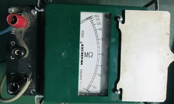
Traditional analog Meggers have a moving pointer that indicates the resistance value on a calibrated scale. Modern digital Meggers feature LCD or LED displays that show precise numerical readings often with additional information such as test voltage, test duration, and diagnostic messages. Digital displays are easier to read and eliminate parallax errors common with analog meters.
4.4 Test Leads and Terminals
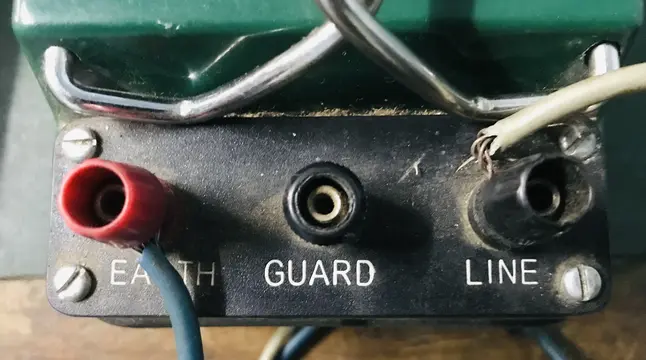
Every Megger comes with test leads that connect the instrument to the equipment being tested. Most Meggers have three terminals labeled Line (L), Earth (E), and Guard (G). The Line terminal connects to the conductor whose insulation is being tested. The Earth terminal connects to ground or the outer surface of the insulation. The Guard terminal is used for special testing situations to eliminate surface leakage currents from affecting the measurement.
5. Types of Megger
Meggers come in various types to suit different applications, working environments, and accuracy requirements.
5.1 Hand-Cranked Megger (Manual Megger)
The hand-cranked Megger is the traditional type that has been used for over a century. It contains a hand-operated DC generator that produces the test voltage when the operator turns the crank at a steady speed.

These instruments are completely self-contained and don’t require batteries or external power making them ideal for field use in remote locations. However, they require consistent cranking to maintain a stable test voltage, which can introduce variables in the test results.
5.2 Motor-Driven Megger
Motor-driven Meggers use an electric motor to drive the internal generator instead of manual cranking. This eliminates operator fatigue and provides more consistent test voltage throughout the measurement. These instruments require a power source either from batteries or mains supply, but they offer more reliable and repeatable results than hand-cranked versions.
5.3 Electronic/Digital Megger

Modern electronic Meggers use solid-state circuitry to generate the test voltage and measure the insulation resistance. They offer numerous advantages over traditional types including higher accuracy, digital displays, data storage capabilities, multiple test voltage options, and advanced features like polarization index calculation and stepped voltage testing. These instruments are now the standard choice for professional electrical testing.
5.4 Battery-Operated Megger
Battery-operated Meggers are a subset of electronic Meggers designed for maximum portability. They use rechargeable or replaceable batteries to power all functions, making them ideal for field testing where mains power is unavailable. Modern lithium-ion battery technology allows these instruments to perform numerous tests on a single charge.
6. Detailed Step-by-Step Testing Procedure
Performing a Megger test correctly requires following a systematic procedure to ensure accurate results and maintain safety. The following detailed procedure will guide you through the complete testing process.
Step 1: Preparation and Safety Measures
Before beginning any Megger test, safety must be your top priority. Start by ensuring that the equipment to be tested is completely de-energized. This means disconnecting it from all power sources not just switching it off. Use a voltage tester to verify that no voltage is present on the equipment. Remember the cardinal rule of electrical safety: treat every conductor as live until you have personally verified it is de-energized.
Lock out and tag out (LOTO) the equipment following your organization’s safety procedures. This prevents someone from accidentally re-energizing the equipment while you’re working on it. Discharge any capacitance that might be present in the equipment by temporarily shorting the conductors to ground. Capacitors, long cable runs, and motor windings can store electrical charge that poses a shock hazard and can affect test results.
Ensure you are wearing appropriate personal protective equipment (PPE). This includes safety glasses, insulated gloves rated for the test voltage you’ll be using, and safety shoes. Work in a dry environment whenever possible as moisture can affect both test results and safety.
Step 2: Inspect and Prepare the Megger
Before connecting the Megger to any equipment, inspect the instrument itself. Check the test leads for any damage, cracks, or exposed conductors. Damaged leads can cause inaccurate readings or safety hazards. Ensure all connections are clean and secure.
Verify that the Megger is functioning correctly by performing a simple verification test:
- Open Circuit Test: With the test leads not connected to anything, perform a test. The Megger should read infinity (∞) or a very high resistance value. This confirms that the instrument correctly indicates when no current path exists.
- Short Circuit Test: Connect the Line and Earth leads together and perform a test. The Megger should read zero or very close to zero ohms. This confirms that the instrument correctly indicates when a direct current path exists.
If the Megger fails either of these verification tests, do not use it until it has been repaired and calibrated.
Step 3: Select the Appropriate Test Voltage
Selecting the correct test voltage is important for obtaining meaningful results without damaging the equipment being tested. Using too low a voltage may not stress the insulation enough to reveal weaknesses, while too high a voltage could damage good insulation or equipment.
General guidelines for test voltage selection based on equipment rated voltage are as follows:
- Equipment rated up to 250V: Use 250V or 500V test voltage
- Equipment rated 250V to 1000V: Use 500V or 1000V test voltage
- Equipment rated above 1000V: Use test voltage equal to or slightly above the rated voltage
- For new installations: Test voltage can typically be higher than for aged equipment
- For old or suspect equipment: Use lower test voltages to avoid damage
When in doubt, consult the equipment manufacturer’s recommendations or relevant testing standards for your industry.
Step 4: Connect the Megger to the Equipment
Proper connection is essential for accurate results. Clean the connection points on the equipment to remove any dirt, dust, or corrosion that might affect the measurement. The connection method depends on what you’re testing.
For Cable Testing:
Connect the Line terminal to the conductor being tested and the Earth terminal to the cable’s metallic sheath, armor, or a grounding point. If testing conductor-to-conductor insulation, connect Line to one conductor and Earth to the other conductor.
For Motor Testing:
Disconnect the motor from its power supply and any connected load. Connect the Line terminal to one or more motor windings (often connected together for this test) and the Earth terminal to the motor frame or ground.
For Transformer Testing:
Disconnect the transformer from all circuits. Connect Line to the winding being tested and Earth to the tank, core, or other windings that are grounded together.
The Guard terminal, when used, should be connected to intercept surface leakage currents that would otherwise be included in the measurement. This is particularly important when testing equipment with surface contamination or when very precise measurements are required.
Step 5: Perform the Test
Once everything is connected and verified, you can perform the actual test. Ensure that no personnel are in contact with the equipment being tested, as dangerous voltages will be present during the test.
Start the test by pressing the test button or, for hand-cranked models, turning the crank at the specified speed. Maintain the test voltage for the required duration. For spot readings, 60 seconds is typically adequate. For more comprehensive tests like the Polarization Index test, you’ll need to maintain the voltage for 10 minutes.
During the test, observe the reading on the display. With analog meters, the pointer will move from zero toward infinity as the capacitive charging current diminishes. With digital instruments, you’ll see the resistance value increasing as the insulation charges. The final steady reading is your insulation resistance value.
Step 6: Record and Interpret Results
Record the test results immediately, along with all relevant information including the date, time, test voltage, temperature, humidity, equipment identification, and any observations about the equipment condition. This documentation is valuable for trending and comparison in future tests.
For most electrical equipment, a minimum insulation resistance of 1 megohm (1 MΩ) per 1000V of operating voltage is considered acceptable, with a minimum of 1 MΩ. For example, a motor rated at 3300V should have at least 3.3 MΩ of insulation resistance. However, many healthy pieces of equipment will show much higher readings often hundreds or thousands of megohms.
More important than absolute values is the trend over time. A reading of 50 MΩ might be acceptable in itself, but if the same equipment showed 500 MΩ six months ago, the decrease indicates deteriorating insulation that requires attention.
Step 7: Safely Discharge and Disconnect
After completing the test, you must safely discharge any electrical charge stored in the equipment’s capacitance. Many modern Meggers include an automatic discharge feature that activates when the test is completed. If your instrument doesn’t have this feature, keep the test leads connected and short the conductors to ground through an appropriate discharge resistor.
Never disconnect the test leads immediately after testing without discharging first. The stored charge can deliver a dangerous shock. Wait for the voltage to decay to safe levels before removing the connections.
Download the Complete PDF on How to Use Megger.
7. Advanced Megger Testing Methods
Beyond the basic spot reading test, several advanced testing methods provide additional diagnostic information about insulation condition.
7.1 Polarization Index (PI) Test
The Polarization Index test compares insulation resistance readings taken at two different time intervals at 1 minute and 10 minutes. The PI is calculated by dividing the 10-minute reading by the 1-minute reading. Good insulation will show an increasing resistance over time as absorption currents diminish resulting in a PI greater than 2. Marginal insulation typically shows a PI between 1 and 2, while deteriorated insulation may show a PI less than 1 (resistance actually decreasing over time due to heating effects).
This test is particularly valuable for evaluating motors, generators, and transformers where insulation condition is critical and trending over time is important.
7.2 Dielectric Absorption Ratio (DAR)
The Dielectric Absorption Ratio is similar to the Polarization Index but uses shorter time intervals 30 seconds and 60 seconds. The DAR is calculated by dividing the 60-second reading by the 30-second reading. This test is useful when time constraints prevent a full 10-minute PI test while still providing insight into insulation quality.
7.3 Step Voltage Test
In a step voltage test, the insulation is tested at progressively higher voltages, for example at 500V, 1000V, 2500V, and 5000V. Good insulation will show relatively constant resistance regardless of applied voltage. If insulation resistance drops as voltage increases it indicates that the insulation has weaknesses that only become apparent under higher electrical stress.
8. Interpretation of Megger Test Results
Results must be analyzed in context considering factors such as temperature, humidity, equipment type, and historical readings.
8.1 Temperature Correction
Insulation resistance varies inversely with temperature as temperature increases, resistance decreases. For accurate comparison of readings taken at different times results should be corrected to a standard temperature, typically 40°C (104°F) or 20°C (68°F).
The general rule is that insulation resistance doubles for every 10°C decrease in temperature and halves for every 10°C increase. Most testing standards provide correction factors or formulas for temperature normalization.
8.2 Humidity Effects
High humidity can reduce insulation resistance readings especially for equipment that has been idle or stored in damp conditions. If possible, test when humidity is moderate and consistent with previous test conditions. For equipment exposed to moisture, a “dry-out” procedure may be necessary before testing to obtain meaningful baseline readings.
8.3 Trending Analysis
Single readings, while useful for determining if equipment meets minimum requirements, tell only part of the story. Regular periodic testing and trend analysis reveal much more about insulation condition. Plotting insulation resistance over time shows whether insulation is stable, slowly degrading, or deteriorating rapidly. A gradual decline over years might be normal aging, while a sudden drop indicates a problem requiring immediate attention.
8.4 Minimum Acceptable Values
While specific requirements depend on equipment type and applicable standards, the following general minimums are widely accepted:
- New equipment: Typically 100 MΩ or higher
- Equipment in service: Minimum 1 MΩ per 1000V operating voltage, with absolute minimum of 1 MΩ
- Critical equipment: Often requires higher minimums as specified by manufacturer or applicable codes
9. Common Applications of Megger
The Megger finds applications across virtually every sector where electrical systems are installed and maintained.
9.1 Power Generation
In power plants, Meggers are used extensively to test generators, excitation systems, and auxiliary equipment. Generator stator and rotor windings require regular insulation testing to ensure reliable operation. The high cost of generator failures, both in repair expenses and lost production, makes regular Megger testing a sound investment.
9.2 Industrial Maintenance
Manufacturing facilities use Meggers to test motors, control systems, and power distribution equipment. Regular testing helps prevent unexpected failures that would halt production. Many plants include insulation resistance testing in their predictive maintenance programs.
9.3 Building Electrical Systems
Electricians use Meggers to test building wiring during installation and renovation. Before energizing new circuits, insulation resistance testing verifies that the installation is free from faults that could pose safety hazards. This testing is often required by electrical codes and inspection authorities.
9.4 Utility Systems
Electric utilities test underground cables, overhead lines, transformers, and switchgear using Meggers. Cable testing is particularly important because underground cable faults are expensive to locate and repair. Regular testing helps utilities identify deteriorating cables before they fail in service.
9.5 Marine and Offshore Applications
Ships, oil platforms, and other marine installations face harsh environmental conditions that accelerate insulation deterioration. Salt water, humidity, and vibration all take their toll on electrical systems. Regular Megger testing is important for maintaining safety and reliability in these challenging environments.
10. Safety Precautions When Using a Megger
Safety cannot be overemphasized when working with Meggers. The high voltages these instruments produce can cause severe injuries or fatalities if proper precautions are not followed.
Essential Safety Practices:
- Always de-energize equipment before testing and verify that it is de-energized using an appropriate voltage detector
- Implement proper lockout/tagout procedures to prevent accidental re-energization
- Post warning signs alerting others that high-voltage testing is in progress
- Never touch equipment, test leads, or connections while a test is in progress
- Always discharge equipment after testing before removing connections
- Use test leads and accessories rated for the test voltage being applied
- Inspect test leads for damage before each use
- Work in dry conditions whenever possible
- Wear appropriate PPE including insulated gloves and safety glasses
- Never test energized equipment—Meggers are designed for testing de-energized systems only
- Be aware of stored energy in capacitors and long cable runs
11. Advantages and Limitations of Megger Testing
11.1 Advantages
- Megger testing is non-destructive when performed correctly allowing equipment to be tested repeatedly over its lifetime without causing damage.
- The instruments are portable and relatively easy to use, making them practical for field testing.
- Results are available immediately for quick decisions about equipment condition.
- The testing method is well-established with decades of historical data and proven correlation to insulation condition.
- Modern digital Meggers offer high accuracy, data storage, and advanced diagnostic features.
11.2 Limitations
- Megger testing only assesses insulation resistance under DC voltage stress, which differs from the AC voltage stress that equipment experiences in normal operation.
- Some types of insulation defects, such as certain forms of tracking or treeing in cables, may not be detected by Megger testing.
- Results are influenced by temperature and humidity, requiring corrections for accurate trending.
- Megger testing cannot locate the specific position of a fault.
- Very long cable runs may show lower readings due to distributed capacitance and natural leakage even when insulation is healthy.
12. Conclusion
A Megger is one of the most valuable instruments in an electrical engineer’s or maintenance technician’s toolkit. It provides direct, measurable insight into the condition of electrical insulation. The testing procedure itself is straightforward: de-energize, isolate, disconnect at both ends, verify the instrument, connect the leads, apply the voltage for 60 seconds, record the reading, and discharge the equipment.
But accurate results demand more than just pushing a button. You need to correct for temperature, select the right test voltage, and maintain detailed records over time. Industry standards like IEEE Std 43, ANSI/NETA ATS, and IEC 60364-6 provide clear guidelines for minimum acceptable values and test procedures. Follow them. Build a trending database for every piece of equipment in your facility. The patterns you capture over months and years of consistent testing will protect your equipment, your personnel, and your bottom line.
13. Frequently Asked Questions (FAQs)
The answer depends on the motor type and winding class. Per IEEE Std 43, the absolute minimum for random-wound stator coils rated below 1kV is 5 MΩ at 40°C. For form-wound coils rated 1kV and above (built after 1970), the minimum is 100 MΩ at 40°C. In practice, healthy motors read much higher than these minimums.
No. A standard multimeter applies only about 9V DC on its ohms range. This is far too low to stress the insulation and detect weaknesses.
There is no single answer. The frequency depends on the age of the equipment, the operating environment, and the criticality of the asset. As a general guideline, motors and generators in industrial plants should be tested annually at minimum.
For equipment rated between 440V and 1000V, a test voltage of 1000V is commonly used. Some technicians prefer 500V for older or suspect motors.
This is normal and expected. The capacitive charging current drops almost immediately. The absorption current drops more slowly over 1 to 10 minutes. As these two currents decrease, the total measured current drops and the calculated insulation resistance rises. The reading at 60 seconds is the standard spot reading.
A zero reading indicates a dead short — the insulation has completely failed and there is a direct conductive path between the conductor and ground (or between conductors). Do not energize this equipment. Investigate and repair the fault before returning the equipment to service.
No. Capacitive equipment stores charge from the high-voltage test. Always discharge the equipment fully before disconnecting the test leads or touching any conductors.
The guard terminal is a third connection that diverts surface leakage current away from the measurement circuit. Use it when testing transformers (guard the untested winding), HV bushings (wrap a bare wire around the bushing midsection), or multi-conductor cables (guard the conductors you are not testing). It gives you a more accurate measurement of the true insulation resistance.