Power transformers are among the most expensive and valuable assets in any electrical power system. Protecting them from thermal damage requires accurate temperature monitoring at all times. One of the most effective methods of monitoring transformer winding temperature is through the Winding Temperature Indicator (WTI), which uses a dedicated Current Transformer known as the WTI CT. This small but powerful component plays a direct role in simulating the hot spot temperature of the transformer winding. Without it, operators would have no reliable way to predict thermal overloads before they cause permanent insulation damage or transformer failure.
In this technical guide, we will discuss everything you need to know about WTI CT in transformers, including its working principle, construction, specifications, selection criteria, wiring details, associated standards, testing procedures, and practical applications. Real-world examples are included throughout to help you apply these concepts in your engineering projects with confidence.
1. What Is a WTI CT in a Transformer?
A WTI CT is a small current transformer that is specifically installed to supply a proportional current to the Winding Temperature Indicator (WTI) of a power transformer. It is not used for metering or protection purposes. Its sole function is to feed a current signal into a heating element inside the WTI gauge.
The WTI CT is usually mounted on the transformer bushing turret or on the bushing itself. It senses the load current flowing through the primary or secondary windings of the transformer. The output of this CT is connected to a small resistive heater coil placed inside the WTI pocket, which is immersed in the top oil of the transformer. This heater coil raises the temperature reading above the actual top oil temperature to simulate the winding hot spot temperature.
The ratio and burden of the WTI CT are carefully selected by the transformer manufacturer to match the thermal characteristics of that specific transformer. This makes the WTI CT a transformer-specific component, not a generic one.
2. Why Is Winding Temperature Monitoring Necessary?
The insulation life of a transformer is directly related to the temperature of the winding hot spot. According to IEEE C57.91, the rate of insulation aging doubles for every 6 to 8 degrees Celsius rise above the rated hot spot temperature. This means even a small thermal overload, if sustained for long periods, can reduce the operational life of the transformer.
Oil temperature alone does not give an accurate picture of the actual winding temperature. The winding hot spot is always hotter than the surrounding oil due to the I²R losses in the copper conductors and eddy current losses. The temperature difference between the top oil and the winding hot spot is called the “hot spot gradient“.
A WTI simulates this gradient using the current signal from the WTI CT. Without this current signal, the WTI would behave just like an Oil Temperature Indicator (OTI), and the operator would never know the actual thermal condition of the winding.
3. How Does the WTI CT Work?
The working principle of the WTI CT is straightforward. It operates on the same electromagnetic induction principle as any other current transformer. The primary conductor passes through the CT core, and a proportional secondary current is generated.
Here is a step-by-step explanation of how it works in a transformer thermal monitoring circuit:
Step 1: The load current flows through the transformer bushing. The WTI CT is installed around this bushing.
Step 2: The WTI CT produces a secondary current proportional to the load current. For example, if the CT ratio is 600/5A and the load current is 600A, the secondary current will be 5A.
Step 3: This secondary current flows through a calibrated heating element (resistor) placed inside the WTI thermal pocket.
Step 4: The heating element generates heat proportional to I²R, where I is the secondary current and R is the resistance of the heater.
Step 5: This heat adds to the top oil temperature sensed by the WTI bulb. The combined reading is the simulated winding hot spot temperature.
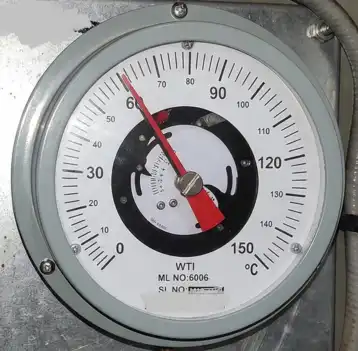
Step 6: The WTI gauge displays this simulated temperature. If it crosses preset alarm or trip thresholds, protective relays or cooling systems are activated.
This method is called the “thermal image” technique. The WTI CT is the source of the thermal image current.
4. Construction and Mounting of WTI CT
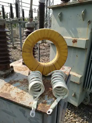
The WTI CT is a ring-type or window-type current transformer with a toroidal core. It is compact in size because it only needs to supply a few amperes to a small heater coil. The core material is usually grain-oriented silicon steel or sometimes a nanocrystalline alloy for better accuracy.
The CT is mounted directly over the bushing conductor, inside the bushing turret of the transformer. In some designs, it is mounted externally on the bushing flange. The mounting location depends on the transformer manufacturer’s design and the available space in the turret.
The secondary terminals of the WTI CT are brought out through a terminal block on the transformer tank. From there, shielded cables connect the CT output to the WTI heater coil. The cable length should be kept as short as possible to minimize additional burden on the CT.
For three-phase transformers, there is usually one WTI CT per phase. However, in many practical installations, only one CT is used — typically on the phase that carries the highest current or the phase with the highest thermal loading.
5. WTI CT Specifications and Ratings
The specifications of a WTI CT are always determined by the transformer manufacturer based on the thermal design of the transformer. Below are the common parameters specified for a WTI CT:
- CT Ratio: This depends on the rated current of the transformer winding. Common ratios include 200/5, 400/5, 600/5, 800/5, 1000/5, 1200/5, and 2000/5.
- Burden: The burden of the WTI CT is very low because it only drives a small heater element and values range from 1 VA to 15 VA.
- Accuracy Class: Since the WTI CT is not used for metering or protection, it does not need to conform to standard accuracy classes like 0.5 or 5P20. However, reasonable accuracy is required for proper thermal simulation.
- Insulation Level: The CT must withstand the full BIL (Basic Impulse Level) of the transformer bushing, as it is installed in the bushing turret area.
- Thermal Rating: The CT must continuously handle the rated current and must also withstand short-circuit currents without damage.
- Frequency: Standard power frequency, 50 Hz or 60 Hz depending on the region.
Here is an example specification table for a WTI CT used on a 20 MVA, 66/11 kV transformer:
| Parameter | HV Side WTI CT | LV Side WTI CT |
|---|---|---|
| CT Ratio | 200/5 A | 1200/5 A |
| Burden | 5 VA | 10 VA |
| Insulation Class | 72.5 kV | 12 kV |
| Core Type | Toroidal | Toroidal |
| Mounting | Bushing Turret | Bushing Turret |
6. Difference Between WTI CT and Protection/Metering CT
Many engineers confuse the WTI CT with the protection or metering CTs installed on the transformer bushings. Although they look similar and operate on the same principle, they serve entirely different purposes.
A protection CT is designed to accurately reproduce fault currents and has a defined accuracy limit factor (ALF), such as 5P20 or 10P10 as per IEC 61869. A metering CT is designed for high accuracy at normal load currents and has accuracy classes like 0.2 or 0.5.
A WTI CT, on the other hand, does not need to reproduce fault currents or maintain tight accuracy over a wide range. It only needs to produce a current proportional to the load current at normal operating conditions. Its output is not fed to any digital relay or meter. It goes directly to a resistive heater element.
The burden of a WTI CT is also much lower than that of a protection or metering CT. A protection CT might have a burden of 30 VA or more, while a WTI CT burden is often below 10 VA.
Another difference is that the WTI CT secondary is often terminated with a fixed resistance (the heater element), not with a variable load like relay coils or meter windings. This makes the circuit simpler but also means the CT must be properly matched to the heater resistance.
7. Relevant Standards and Codes
Several industry standards govern the design, installation, and testing of winding temperature indicators and their associated CTs. Here are the most relevant ones:
- IEEE C57.12.00 — This standard covers the general requirements for liquid-immersed distribution, power, and regulating transformers. It includes requirements for temperature indicators, including WTI specifications.
- IEEE C57.91 — This guide covers loading practices for mineral-oil-immersed transformers. It provides detailed methods for calculating winding hot spot temperatures, which is the theoretical foundation for the WTI thermal image method.
- IEC 60076-2 — This part of the IEC transformer standard deals with temperature rise. It specifies the permissible temperature rise limits for windings and oil.
- ANSI C57.12.90 — This standard covers test procedures for liquid-immersed transformers and includes provisions for testing temperature indicators.
- IEC 61869-2 — Although this standard primarily covers current transformers for metering and protection, it provides useful reference information for CT construction and testing.
8. WTI CT Wiring and Circuit Diagram
The wiring of the WTI CT circuit is simple but must be done correctly to avoid errors in temperature indication.
The secondary of the WTI CT is connected in a dedicated circuit, separate from the protection and metering CT circuits. The two leads from the CT secondary go directly to the WTI heater element terminals on the transformer tank junction box.
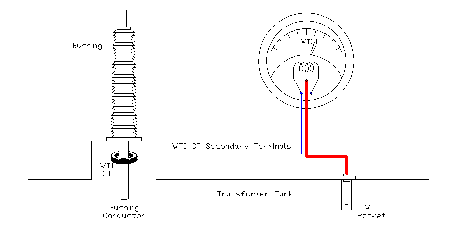
Here is a basic circuit description:
- WTI CT secondary terminal S1 connects to heater terminal H1 of the WTI gauge.
- WTI CT secondary terminal S2 connects to heater terminal H2 of the WTI gauge.
- The circuit is a simple series loop. No other equipment is connected in this loop.
- The CT secondary must never be left open-circuited when the transformer is energized. If the WTI is removed for maintenance, the CT secondary must be short-circuited.
Some WTI gauges have an additional calibration resistor that can be adjusted during commissioning to fine-tune the temperature indication. This resistor is connected in series or parallel with the heater element.
The cable used for WTI CT wiring should be rated for the secondary current (usually 5A or 1A) and should be shielded if the cable run is long. The cable resistance adds to the total burden of the CT, so it must be accounted for during design.
9. Calibration and Testing of WTI CT
Calibration of the WTI CT system is performed during transformer commissioning. The goal is to verify that the WTI gauge reads the correct simulated winding temperature at rated load conditions.
Ratio Test: The CT ratio is verified by injecting a known primary current and measuring the secondary output. The ratio should match the nameplate value within acceptable tolerances.
Polarity Test: Although polarity is not as important for the WTI heater circuit as it is for protection CTs, it should still be verified to maintain consistency.
Burden Test: The total burden of the circuit (heater resistance + cable resistance) is measured and compared with the CT rated burden to confirm the CT is not overloaded.
Thermal Image Test: This is the most important test. It involves injecting rated current into the WTI CT primary (or a proportional current into the secondary) and observing the WTI gauge reading. The reading should match the expected value calculated from the transformer’s thermal design data.
For example, if the transformer has a rated top oil rise of 55°C and a winding gradient of 15°C, then at rated load, the WTI should read approximately 15°C above the OTI reading. The WTI CT and heater must be calibrated to produce this 15°C differential.
Insulation Resistance Test: A megger test is performed on the CT secondary winding to verify the insulation integrity. A minimum of 500V DC is typically used.
10. Alarm and Trip Settings of the WTI
The WTI gauge is equipped with adjustable contacts that can be set to trigger alarms or trips at predefined temperatures. These settings are based on the transformer’s thermal ratings and the applicable standard.
According to IEEE C57.12.00 and IEC 60076-2, the following are common alarm and trip Settings of WTI for oil-filled transformers:
| Setting | Typical Value (°C) |
|---|---|
| WTI Alarm | 105°C |
| WTI Trip | 120°C |
| OTI Alarm | 85°C |
| OTI Trip | 95°C |
11. Common Problems and Troubleshooting
Several issues can arise with the WTI CT circuit during the life of a transformer. Here are some common problems and their solutions:
11.1 WTI reading equals OTI reading
This indicates that the heater element is not receiving current. Check the WTI CT secondary circuit for open connections, blown fuses (if any), or a damaged heater element. Also verify that the CT is properly installed around the bushing conductor.
11.2 WTI reading is excessively high.
This could be caused by a short circuit in the CT secondary, incorrect CT ratio, or a wrong heater element resistance. Verify the CT ratio and measure the heater resistance with a multimeter.
11.3 WTI reading fluctuates erratically.
Loose connections in the CT secondary circuit can cause intermittent contact, leading to erratic readings. Tighten all terminal connections and check the cable for damage.
11.4 WTI gauge is stuck or not moving.
The mechanical linkage inside the WTI gauge may be jammed. This is a gauge problem, not a CT problem. The gauge should be sent to the manufacturer for repair or replacement.
12. Practical Example: WTI CT Selection for a 40 MVA Transformer
Let us work through a practical example to illustrate how a WTI CT is selected.
Transformer Rating: 40 MVA, 132/33 kV, three-phase, ONAN/ONAF cooling.
HV Rated Current: \(\dfrac{40,000}{(1.732 \times 132)} = 175 A\)
LV Rated Current: \(\dfrac{40,000}{(1.732 \times 33)} = 700 A\)
12.1 WTI CT on HV Side
The nearest standard CT ratio for 175A primary current would be 200/5 A. The heater element resistance would be designed by the WTI gauge manufacturer to produce the correct winding gradient at 5A (corresponding to rated current of approximately 175A through the CT primary).
12.2 WTI CT on LV Side:
The nearest standard CT ratio for 700A primary current would be 800/5 A. Again, the heater element would be calibrated for the expected winding gradient at the corresponding secondary current.
Most transformer OEMs prefer to install the WTI CT on the LV side because the LV current is higher and gives a stronger thermal image signal. However, the choice depends on the specific design.
13. Conclusion
The WTI CT is a small but highly functional component in a power transformer’s thermal protection system. It provides the current signal needed to simulate the winding hot spot temperature, which is the most important parameter for assessing transformer insulation health and remaining life. Proper selection, installation, wiring, and calibration of the WTI CT are necessary to achieve accurate winding temperature readings.
Engineers and maintenance personnel must understand how this component works and how to troubleshoot it when issues arise. Following the applicable IEEE and IEC standards during design and testing will help maintain the reliability of the transformer’s thermal monitoring system. A well-functioning WTI CT system directly contributes to safer transformer operation, extended equipment life, and reduced risk of unexpected failures.
14. Frequently Asked Questions
WTI CT stands for Winding Temperature Indicator Current Transformer. It is a dedicated CT used to supply current to the heater element inside the WTI gauge for thermal image simulation.
The WTI CT is installed around the bushing conductor inside the bushing turret of the transformer. In some designs, it is mounted externally on the bushing flange.
No. The WTI CT is designed specifically for the thermal image circuit. Its burden, accuracy, and rating are not suitable for protection or metering applications.
An open-circuited CT can develop very high and dangerous voltages at its secondary terminals. It must always be short-circuited if the WTI gauge or heater element is disconnected.
If the WTI reads higher than the OTI by the expected winding gradient at rated load, the CT is working correctly. If the WTI and OTI readings are the same, the CT circuit may be faulty.
Common ratios include 200/5, 400/5, 600/5, 800/5, 1000/5, 1200/5, and 2000/5. The exact ratio depends on the rated current of the transformer winding.
Not all transformers have WTI CTs. Small distribution transformers usually have only an OTI. Power transformers rated above 5 MVA typically have both OTI and WTI, with the WTI requiring a dedicated CT.
Changing the CT ratio after manufacturing is not recommended because the heater element is calibrated for a specific CT ratio. Any change would require recalibration of the entire thermal image system.