A 3-way switch allows you to control a single light fixture from two different locations. This is one of the most common switching configurations used in residential and commercial electrical systems across North America. You will find 3-way switches installed at stairways, hallways, bedrooms with multiple entries, and garages.
The circuit uses two single-pole double-throw (SPDT) switches connected by a pair of traveler wires. The light turns on or off depending on whether both switches route power through the same traveler wire or through different ones. This concept is simple in theory but requires careful attention to wiring details during installation.
In this technical guide, we will discuss everything you need to know about 3-way switch wiring diagrams, including the working principle, terminal identification, circuit configurations, traveler wire functions, step-by-step installation procedures, NEC and ANSI code references, common wiring mistakes, and troubleshooting methods. Practical examples are included throughout to help you apply these concepts in real-world scenarios confidently.
1. What is a 3-Way Switch?
A 3-way switch is a single-pole double-throw (SPDT) switch with three screw terminals and one ground terminal. It does not work like a standard single-pole switch that simply opens or closes a circuit. Instead, it redirects electrical current from one path to another. Two 3-way switches are always used together in a pair to control one light fixture or electrical load from two separate locations.
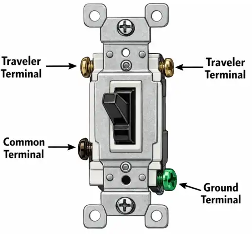
The three terminals on a 3-way switch are:
1.1 Common Terminal
This is the most important terminal on the switch. It is usually a darker color (black or dark brass) and is set apart from the other two terminals. On the power-entry switch (Switch 1), the common terminal receives the incoming hot wire from the electrical panel. On the load-side switch (Switch 2), the common terminal sends the switched hot wire to the light fixture.
1.2 Traveler Terminal 1
This is one of two lighter-colored brass or copper terminals. It connects to one of the two traveler wires that run between the switches.
1.3 Traveler Terminal 2
This is the second lighter-colored terminal. It connects to the other traveler wire. Together, the two traveler terminals provide two alternate paths for current to flow between Switch 1 and Switch 2.
1.4 Ground Terminal
This is the green screw on the switch body. It connects to the bare copper or green-insulated ground wire for safety and equipment grounding per NEC Article 250 and ANSI/NFPA 70.
A 3-way switch does not have “ON” or “OFF” printed on its toggle. The reason is that the switch position alone does not determine whether the light is on or off. The state of the light depends on the combined positions of both switches in the pair.
2. How Does a 3-Way Switch Work?
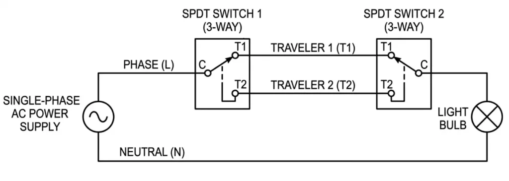
Each 3-way switch contains an internal contact arm that pivots between two positions. In Position A, the contact arm connects the common terminal to Traveler Terminal 1. In Position B, the contact arm connects the common terminal to Traveler Terminal 2. There is no “off” position. The switch is always connected to one traveler or the other.
Two 3-way switches are wired together using two traveler wires. These two wires create two possible paths for current to travel from Switch 1 to Switch 2. The circuit is complete and the light turns on only when both switches route current through the same traveler wire. The circuit is broken and the light turns off when each switch routes current through a different traveler wire.
2.1 The Four Possible Circuit States
There are exactly four combinations of switch positions. Two combinations produce a complete circuit (light ON) and two produce a broken circuit (light OFF).
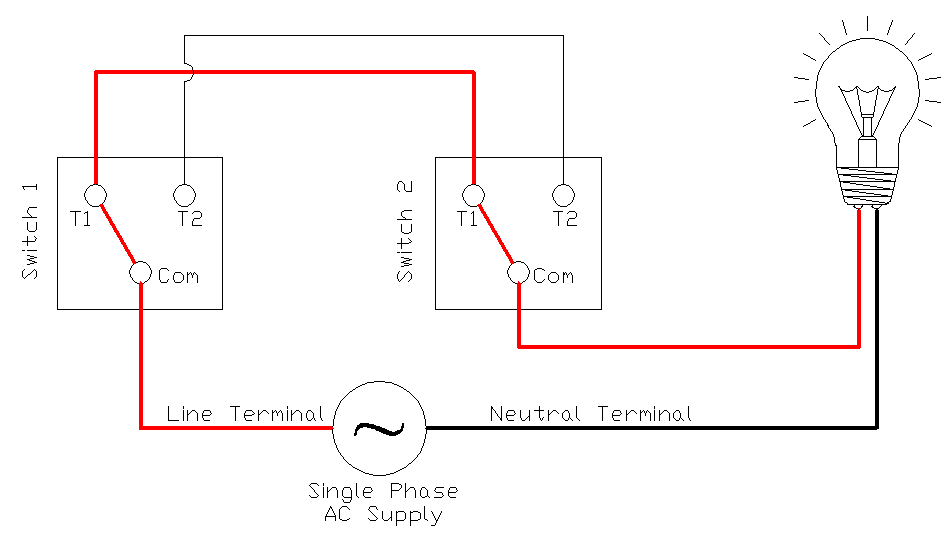
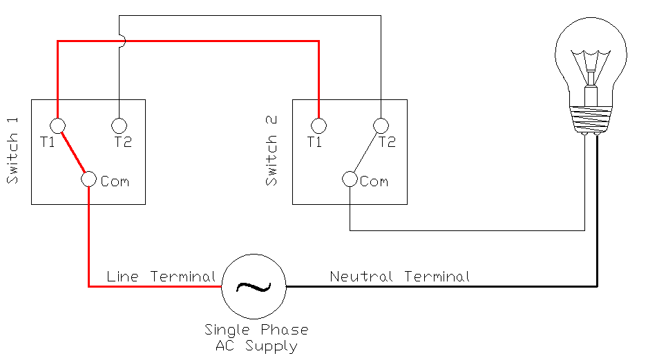
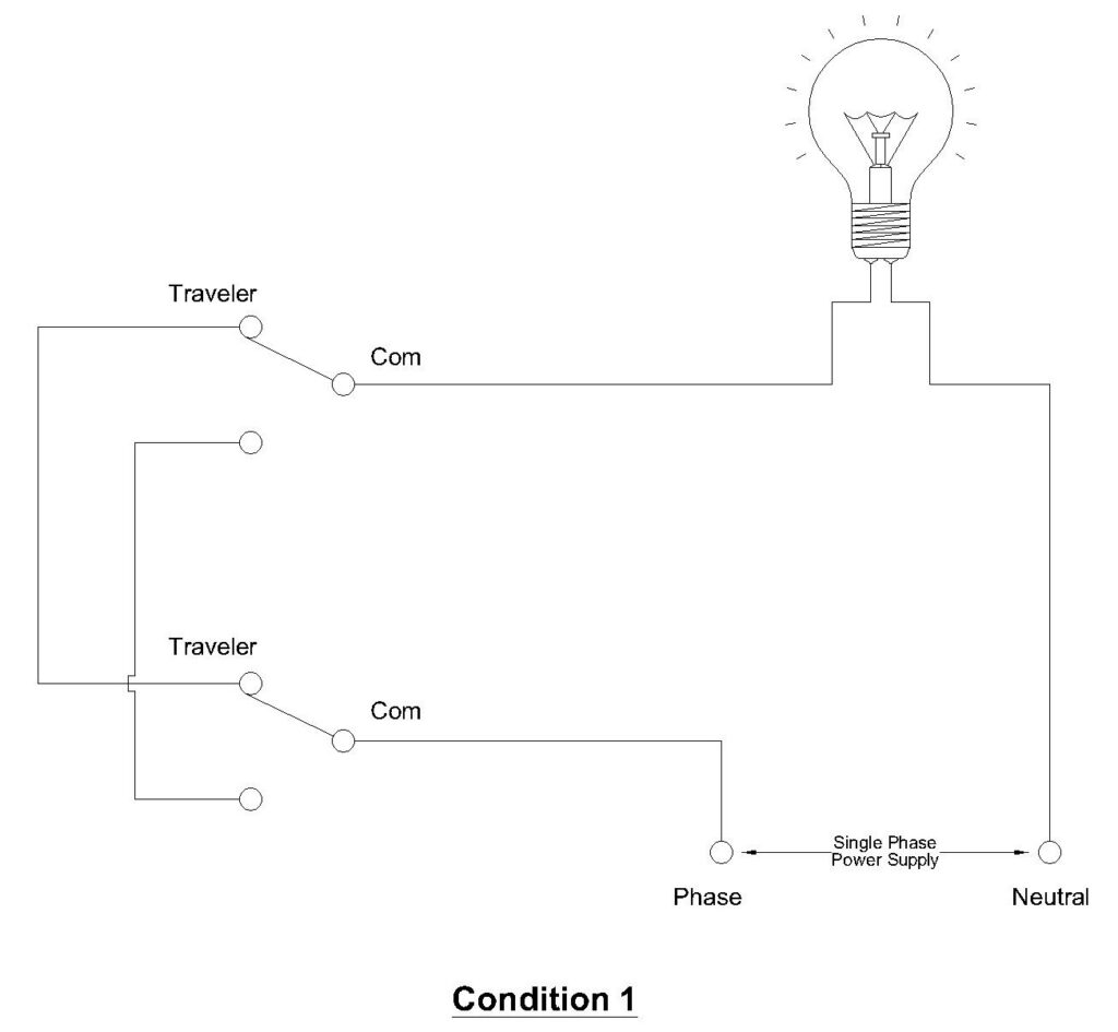
2.1.1 State 1 — Light ON
Switch 1 is in Position A. Switch 2 is in Position A. Both switches connect to Traveler Wire 1. Current flows from the hot wire through Switch 1’s common terminal, out through Traveler Wire 1, into Switch 2’s Traveler Terminal 1, through Switch 2’s common terminal, and to the light fixture. The neutral wire completes the circuit back to the panel.
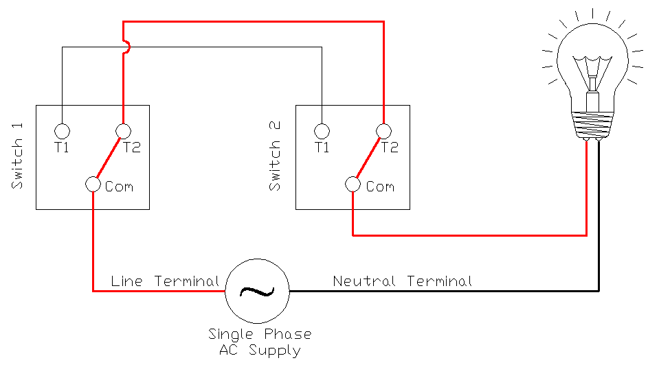
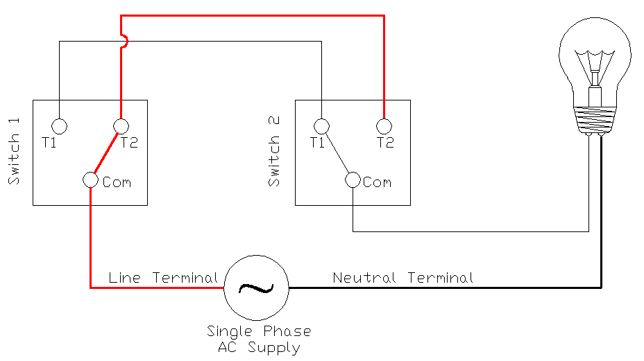
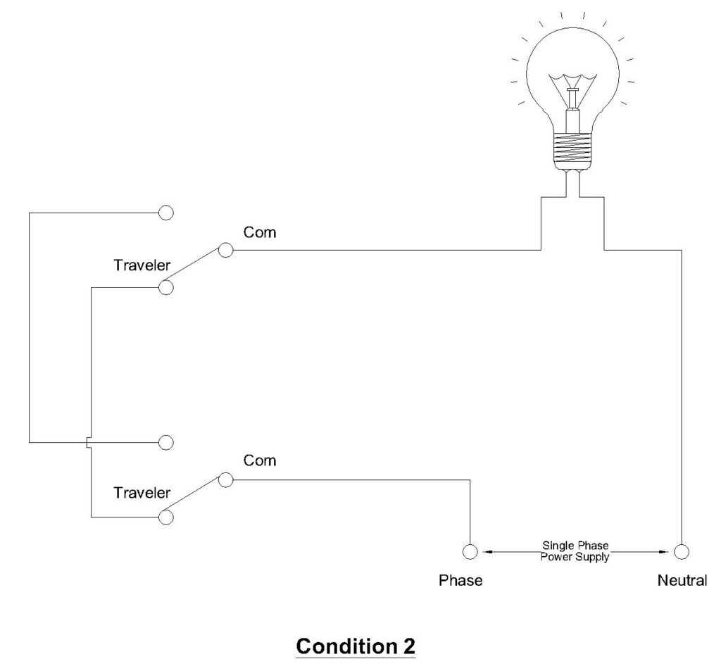
2.1.2 State 2 — Light ON
Switch 1 is in Position B. Switch 2 is in Position B. Both switches connect to Traveler Wire 2. Current flows through the same type of path but uses the second traveler wire instead. The result is the same, the circuit is complete and the light is on.
2.1.3 State 3 — Light OFF
Switch 1 is in Position A (connected to Traveler Wire 1). Switch 2 is in Position B (connected to Traveler Wire 2). The current leaving Switch 1 through Traveler Wire 1 arrives at Switch 2’s Traveler Terminal 1, but Switch 2’s contact arm is connected to Traveler Terminal 2. There is no path to the common terminal. The circuit is broken and the light is off.
2.1.4 State 4 — Light OFF
Switch 1 is in Position B (connected to Traveler Wire 2). Switch 2 is in Position A (connected to Traveler Wire 1). The same mismatch occurs in reverse. The circuit is broken and the light is off.
This is the core principle of 3-way switching. Flipping either switch changes the circuit from one state to another. If the light is on, flipping either switch will turn it off. If the light is off, flipping either switch will turn it on.
3. What Are Traveler Wires?
Traveler wires are the two conductors that run between Switch 1 and Switch 2 in a 3-way switch circuit. They do not connect directly to the power source or to the light fixture. Their only job is to carry current between the two switches through one of two possible paths.
In a standard NM (non-metallic sheathed) cable installation per NEC Article 334, the traveler wires are carried inside a 14/3 or 12/3 cable. This cable contains four conductors:
- Black wire — used as Traveler Wire 1
- Red wire — used as Traveler Wire 2
- White wire — used as the neutral conductor
- Bare copper wire — used as the equipment grounding conductor
The black and red wires serve as the two traveler conductors. The white wire passes through the switch boxes without connecting to any switch terminal. It carries neutral current directly from the source to the light fixture.
3.1 Cable Selection for Traveler Wires
The NEC requires that conductor size match the overcurrent protection on the circuit (NEC Article 240). For residential lighting circuits:
- 14 AWG conductors (14/3 NM cable): Rated for 15-ampere circuits
- 12 AWG conductors (12/3 NM cable): Rated for 20-ampere circuits
Between the two switches, always use a 3-conductor cable (plus ground) so that both traveler wires and the neutral are enclosed in a single cable assembly. Between the panel and Switch 1, and between Switch 2 and the light fixture, a 2-conductor cable (plus ground) is sufficient because only one hot or switched conductor is needed along with the neutral and ground.
4. 3-Way Switch Wiring Diagram: Light at the End of the Run
This is the most common 3-way switch configuration. Power enters at Switch 1, travels through the traveler wires to Switch 2, and the light fixture is connected at Switch 2. The neutral wire runs from the source through both switch boxes to the light fixture without being interrupted.
4.1 Wiring Connections at Each Point
4.1.1 At the Electrical Panel
A 14/2 or 12/2 NM cable carries the hot (black), neutral (white), and ground (bare) from the circuit breaker to Switch 1.
4.1.2 At Switch 1 (Power Entry Switch)
- Connect the black wire from the panel cable to the Common terminal (dark screw) on Switch 1. This is the incoming hot wire.
- Connect the black wire from the 14/3 cable (going to Switch 2) to Traveler Terminal 1 on Switch 1.
- Connect the red wire from the 14/3 cable to Traveler Terminal 2 on Switch 1.
- Connect the white wires from both cables together using a wire nut. The neutral passes straight through this box — it does not connect to the switch.
- Connect all bare ground wires together and to the green ground screw on Switch 1. Use a pigtail if needed.
4.1.3 At Switch 2 (Load Side Switch)
- Connect the black wire from the 14/3 cable (coming from Switch 1) to Traveler Terminal 1 on Switch 2.
- Connect the red wire from the 14/3 cable to Traveler Terminal 2 on Switch 2.
- Connect the black wire from the 14/2 cable (going to the light fixture) to the Common terminal (dark screw) on Switch 2. This is the switched hot wire going to the light.
- Connect the white wires from both cables together using a wire nut. The neutral passes through this box as well.
- Connect all bare ground wires together and to the green ground screw on Switch 2.
4.1.4 At the Light Fixture
- Connect the black wire (switched hot from Switch 2) to the hot terminal of the light fixture.
- Connect the white wire (neutral) to the neutral terminal of the light fixture.
- Connect the bare ground wire to the ground terminal or ground screw on the fixture mounting bracket.
5. 3-Way Switch Wiring Diagram: Light in the Middle of the Run
In some installations, the light fixture box sits physically between the two switch locations. Power enters at Switch 1, goes to the light fixture box, and then continues to Switch 2. The wiring in this configuration is more involved because the light fixture box acts as a junction point for multiple cables.
5.1 Wiring Connections at Each Point
5.1.1 At Switch 1 (Power Entry Switch)
- Connect the incoming hot wire (black from panel) to the Common terminal.
- Connect the two traveler wires (black and red from the 14/3 cable going to the light fixture box) to the Traveler Terminals.
- Connect the white neutral wires together with a wire nut (pass-through).
- Connect ground wires to the green ground screw.
5.1.2 At the Light Fixture Box (Junction Point)
This box contains two 14/3 cables — one coming from Switch 1 and one going to Switch 2. It also has the light fixture connections.
- Connect the black traveler from Switch 1’s cable to the black traveler of Switch 2’s cable using a wire nut. These pass through without connecting to the light.
- Connect the red traveler from Switch 1’s cable to the red traveler of Switch 2’s cable using a wire nut. These also pass through.
- Connect all white neutral wires together — from Switch 1’s cable, Switch 2’s cable, and the light fixture’s neutral terminal. Use a wire nut with a pigtail to the fixture.
- The light fixture’s hot terminal connects to a separate conductor. In this configuration, an additional conductor must carry the switched hot from Switch 2’s common terminal back to the fixture. This is where wiring becomes more complex, and some installations use the white wire as a re-identified switched hot conductor per NEC 200.7(C)(2), marked with black tape.
- Connect all ground wires together and to the fixture ground terminal.
5.1.3 At Switch 2
- Connect the traveler wires (black and red from the 14/3 cable) to the Traveler Terminals.
- Connect the switched hot wire to the Common terminal. This wire runs back to the light fixture.
- Connect ground wires to the green ground screw.
This configuration requires careful wire identification. Label all wires before pushing them into the boxes. A label maker or colored tape is very helpful here.
6. Step-by-Step Installation Guide for 3-Way Switches
6.1 Materials Needed
- Two 3-way switches (rated for circuit amperage — 15A or 20A)
- 14/2 or 12/2 NM cable (panel to Switch 1 and Switch 2 to light fixture)
- 14/3 or 12/3 NM cable (between switches)
- Wire nuts (appropriately sized per wire gauge and number of conductors)
- Electrical tape
- Ground pigtails (bare copper, same gauge as circuit wiring)
- Light fixture
- Electrical boxes (sized per NEC 314.16 box fill calculations)
6.2 Tools Needed
- Wire strippers
- Needle-nose pliers
- Phillips and flathead screwdrivers
- Non-contact voltage tester
- Digital multimeter
- Label maker or colored tape
6.3 Installation Procedure
Step 1: Disconnect Power
Turn off the circuit breaker feeding the circuit at the main electrical panel. Lock out the breaker if possible, or place tape over it to prevent accidental re-energization. Use a non-contact voltage tester at the work location to verify that power is off. Test again with a multimeter set to AC voltage mode. Never rely on a single test always confirm with two independent methods per NFPA 70E safe work practices.
Step 2: Verify Box Sizing
Count the number of conductors entering each electrical box. Use NEC 314.16 (Table 314.16(B)) to verify that the box volume is adequate. For 14 AWG conductors, each conductor requires 2.00 cubic inches. For 12 AWG, each requires 2.25 cubic inches. The switch itself counts as two conductors. Ground wires count as one conductor total regardless of how many ground wires are present. If the box is too small, replace it with a deeper box or a two-gang box.
Example: A Switch 1 box with a 14/2 cable entering and a 14/3 cable leaving has the following conductor count:
- 14/2 cable: 2 insulated conductors (black, white)
- 14/3 cable: 3 insulated conductors (black, red, white)
- Grounds: 1 (counted as one regardless of number)
- Switch: 2 (counts as two conductor equivalents)
- Total: 8 conductor equivalents × 2.00 cu in = 16.00 cubic inches minimum
A standard single-gang old work box is about 14 cubic inches. This would be too small. You would need a deeper box or a two-gang box.
Step 3: Run Cables
Run the appropriate cables between all locations. Leave at least 6 inches of free conductor extending from each box per NEC 300.14. Strip approximately 8 inches of the outer NM cable sheath at each box. Strip 3/4 inch of insulation from the end of each individual conductor.
Step 4: Wire Switch 1
Follow the connection instructions described in the “Light at the End of the Run” section above. Make sure the incoming hot (black) wire goes to the common terminal. Make sure both traveler wires go to the traveler terminals. Make sure neutral wires are spliced through without connecting to the switch.
Step 5: Wire Switch 2
Connect the traveler wires to the matching traveler terminals. Connect the switched hot wire to the common terminal. Splice the neutrals through. Connect the grounds.
Step 6: Wire the Light Fixture
Connect the switched hot (black) to the fixture’s hot terminal. Connect the neutral (white) to the fixture’s neutral terminal. Connect the ground (bare) to the fixture’s ground terminal.
Step 7: Secure, Close, and Test
Carefully fold the wires into each box without pinching or crimping them. Screw each switch into its box. Install cover plates. Turn the breaker back on. Test the circuit by flipping each switch individually and verifying that the light toggles on and off from both locations. Test all four states described earlier in this guide.
7. Common Wiring Mistakes and Troubleshooting
Mistake 1: Traveler Wires Connected to the Wrong Terminals
This is the most frequent error. If a traveler wire is accidentally connected to the common terminal instead of a traveler terminal, the circuit will not work correctly. The light may work from only one switch position, or it may not work at all.
How to fix it: Turn off power. Remove the switch from the box. Identify the common terminal — it is the darker-colored screw set apart from the other two. Make sure only the incoming hot (at Switch 1) or the outgoing load wire (at Switch 2) is connected to this terminal. The two traveler wires must connect to the two lighter-colored screws.
Mistake 2: Neutral Wire Interrupted at a Switch Box
The neutral wire must run continuously from the power source to the light fixture. It should not be cut, switched, or terminated at any switch. The neutral wire passes through each switch box as a splice — it is connected to no switch terminal.
How to fix it: Open each switch box and verify that the white wires are spliced together with a wire nut and are not connected to any switch terminal.
Mistake 3: Wrong Cable Type Between Switches
If a 14/2 cable is used between the switches instead of a 14/3 cable, there will be only one traveler wire available. The circuit cannot function with a single traveler. Two traveler conductors are mandatory for 3-way switching.
How to fix it: Replace the cable between the switches with a 14/3 or 12/3 NM cable that provides both traveler conductors, a neutral, and a ground.
Mistake 4: Ground Wires Not Bonded
All ground wires at each box must be bonded together and connected to the green ground screw on the switch or fixture. Missing ground connections create a safety hazard and violate NEC Article 250.
How to fix it: At each box, gather all bare copper ground wires. Twist them together. Add a pigtail wire if needed and connect it to the green ground screw. Use a wire nut or a green grounding connector to secure the splice.
Mistake 5: Reversed Traveler Wire Connections Between Switches
If the black traveler connects to Traveler Terminal 1 on Switch 1 but connects to Traveler Terminal 2 on Switch 2, the switch logic is reversed. The circuit will still function — the light will still toggle on and off from both locations. However, the switching states will be swapped (the light may be on when you expect it to be off, and vice versa). This is not a safety hazard, but it can be confusing.
How to fix it: For clean wiring practice, connect the black traveler to the same relative terminal position on both switches, and the red traveler to the same relative terminal position on both switches. This is not strictly required by code, but it makes future troubleshooting easier.
8. 3-Way Switches vs. 4-Way Switches
A 4-way switch is used only in systems where you need to control a light from three or more locations. In such a system, two 3-way switches are always placed at the beginning and end of the switch chain. One or more 4-way switches are placed in the middle positions between the two 3-way switches.
| Feature | 3-Way Switch | 4-Way Switch |
|---|---|---|
| Number of Terminals | 3 (1 common + 2 travelers) | 4 (2 traveler inputs + 2 traveler outputs) |
| Switch Type | Single-pole double-throw (SPDT) | Crossover switch (swaps traveler pair connections) |
| Number per Circuit | Always 2 | 1 or more (placed between the two 3-way switches) |
| Control Locations | 2 | 3 or more |
| NEC Reference | Article 404 | Article 404 |
A 4-way switch works by either passing the two traveler wires straight through or crossing them over. It does not have a common terminal. It has four traveler terminals two inputs and two outputs. Each time you flip a 4-way switch, it swaps the connections between the traveler pairs, changing the circuit state.
9. Practical Applications
Stairway Lighting: A switch at the bottom and top of the stairs controls the stairway light. You turn the light on before climbing and off after reaching the other floor.
Hallway Lighting: A switch at each end of a hallway lets you control the hall light from either direction. This is especially useful at night.
Bedroom with Ensuite Bathroom: A switch near the bedroom door and another inside the bathroom entrance control the same bedroom light. You do not have to walk across a dark room to reach a switch.
Garage and House Entry: One switch inside the house near the door to the garage and another switch inside the garage control the same garage light. You can turn the light on before entering the garage and turn it off from inside the house after returning.
10. Relevant NEC and ANSI Standards
The following standards apply to 3-way switch installations in North America:
| Standard | Description |
|---|---|
| ANSI/NFPA 70 (NEC) | National Electrical Code — the primary standard governing electrical installations |
| NEC Article 200 | Grounded (neutral) conductors — including re-identification rules (200.7) |
| NEC Article 240 | Overcurrent protection — conductor sizing and breaker ratings |
| NEC Article 250 | Grounding and bonding requirements |
| NEC Article 300 | General wiring methods — including conductor length in boxes (300.14) |
| NEC Article 314 | Boxes, conduit bodies, and fittings — including box fill calculations (314.16) |
| NEC Article 334 | NM-sheathed cable (Romex) installation requirements |
| NEC Article 404 | Switches — installation requirements, grounding, ratings |
| ANSI/UL 20 | Standard for general-use snap switches — product safety listing |
| NFPA 70E | Standard for Electrical Safety in the Workplace — safe work practices |
Always check with your local Authority Having Jurisdiction (AHJ) for any amendments or additional requirements beyond the NEC.
11. Conclusion
The 3-way switch wiring diagram is a foundational topic in residential electrical work and electrical engineering education. The circuit relies on two SPDT switches connected by a pair of traveler wires. The light turns on when both switches connect to the same traveler wire and turns off when they connect to different traveler wires.
Proper installation requires correct terminal identification, appropriate cable types (14/3 or 12/3 NM cable for the traveler run), continuous neutral conductors, and complete ground bonding at every box. Always follow NEC requirements and local code amendments.
Test the installation by verifying all four switching states before closing up the boxes. If you are not comfortable performing electrical work, hire a licensed electrician to do the installation safely and correctly.
12. Frequently Asked Questions (FAQs)
No. A single-pole switch has only two terminals (plus ground) and can only open or close a circuit. It cannot redirect current between two traveler paths. You must use two 3-way switches. They are specifically designed with three terminals to route current through one of two traveler wires.
A 3-way switch does not have fixed ON and OFF positions. The state of the light depends on the combined positions of both switches. Flipping one switch changes the circuit state, but whether the light turns on or off depends on the position of the other switch at that moment.
For a 15-ampere lighting circuit, use 14 AWG conductors (14/2 and 14/3 NM cable). For a 20-ampere circuit, use 12 AWG conductors (12/2 and 12/3 NM cable). The wire gauge must match the circuit breaker rating per NEC Article 240.
Yes, but only one of the two switches can be a dimmer. The other must be a compatible 3-way companion switch. Check the dimmer manufacturer’s instructions to verify compatibility with 3-way wiring.
The circuit will still work. The light will still toggle on and off from both locations. The only difference is that the pairing of switch positions changes. The light may be on in states where it was previously off, and vice versa.
Yes. NEC 404.2(C) requires a neutral conductor in most switch boxes for new installations. This is to accommodate future use of electronic switches, timers, or smart switches that need a neutral to operate.
The common terminal is usually a different color than the two traveler terminals. It is most often a black or dark brass screw, set apart from the two lighter brass or copper traveler screws.
Yes. You can connect multiple light fixtures in parallel on the load side of Switch 2’s common terminal. All the fixtures will turn on and off together from both switch locations.