An anti-pumping relay is a specialized electrical protection device integrated into the closing circuit of circuit breaker control systems to prevent hunting oscillations. Hunting, also known as pumping, is the rapid and uncontrolled repeated closing attempts of a circuit breaker that occur when the control circuit attempts multiple reclosures in quick succession without allowing adequate time for the system to stabilize. This phenomenon causes severe mechanical stress on the breaker contacts, generates excessive electromagnetic stress, and reduces the operational lifespan of power equipment.
In this technical guide we will discuss what is an Anti Pumping Relay, how does Anti Pumping Relay works, circuit diagram, and types with practical examples along with the testing procedures of Anti Pumping Relay.
1. What is Anti Pumping in Circuit Breakers?
Before we understand the anti pumping relay, let’s first understand what “pumping” means in the context of circuit breakers. Pumping refers to the repeated closing and opening of a circuit breaker when the close command signal persists while a fault condition exists in the system.
Imagine you have a circuit breaker with a fault on the load side. An operator presses the close button and keeps it pressed. The circuit breaker closes, detects the fault, and the protection relay trips it open. But since the close button is still pressed, the circuit breaker immediately tries to close again, only to be tripped once more by the protection relay. This cycle continues rapidly causing what we call “pumping.”
This pumping action can cause several serious problems. The mechanical components of the circuit breaker experience excessive wear and tear due to rapid operation. The electrical contacts suffer from severe arcing damage. The circuit breaker’s operating mechanism may fail prematurely. Most importantly, the repeated fault current flow can damage transformers, cables, and other connected equipment.
2. How Does an Anti Pumping Relay Work?
The anti pumping relay works on a simple but effective principle. It monitors the circuit breaker’s position and controls the closing circuit to prevent repeated closing attempts. The relay creates a logical interlock that breaks the closing circuit after one complete close-open operation until the close command is removed and reapplied.
When you press the close button, the anti pumping relay allows the closing signal to reach the circuit breaker’s closing coil. The circuit breaker closes successfully. At this moment, the anti pumping relay notes that a closing operation has occurred and blocks any further closing signals even if the close button remains pressed.
If the circuit breaker trips due to a fault or any other reason while the close button is still pressed, the relay prevents the circuit breaker from closing again. The relay only resets and allows another closing operation when the close command is removed and circuit breaker has (the button is released) and then reapplied (the button is pressed again).
Let’s understand this with a practical example. Suppose a technician is testing a circuit breaker and accidentally keeps the close button pressed. Without an anti pumping relay, if a fault occurs, the breaker would pump continuously. With the anti pumping relay, the breaker closes once, and if it trips, it won’t close again until the technician releases and presses the close button again. This simple action prevents catastrophic equipment damage.
3. Block Diagram of Anti Pumping Relay Circuit
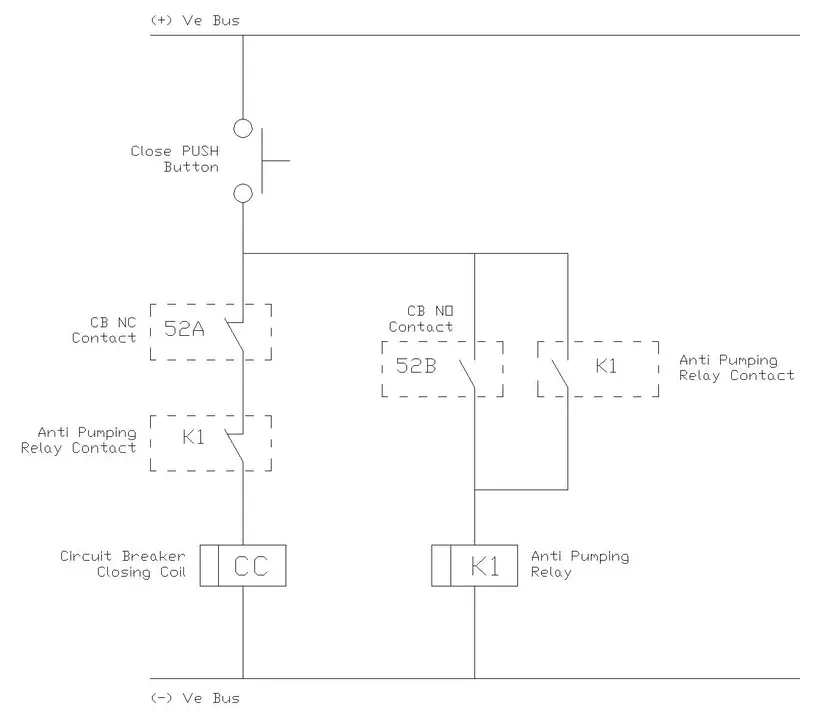
The anti pumping relay auxiliary contact is connected in series with the circuit breaker’s closing coil circuit. The relay has auxiliary contacts that create the necessary interlocking logic. A typical configuration includes the close button, the anti pumping relay contacts, the circuit breaker auxiliary switches, and the closing coil.
The circuit breaker’s auxiliary switch provides feedback to the anti pumping relay about the breaker’s position. When the breaker is open, one set of auxiliary contacts is closed. When the breaker closes, these contacts open, and another set closes.
Here’s a simplified block diagram representation of the control logic:

4. Types of Anti Pumping Schemes
4.1 Electrical Anti Pumping Relay
The electrical anti pumping relay is the most common type used in modern substations. It uses electromagnetic or solid-state logic to create the interlocking function. These relays are compact, reliable, and easy to integrate into control panels. They typically operate on the same DC supply voltage used for the circuit breaker control (usually 110V DC or 220V DC).
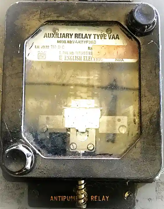
An electrical anti pumping relay monitors the circuit breaker position through auxiliary contacts and controls the closing circuit accordingly. These relays often have indication LEDs to show their operating status.
4.2 Mechanical Anti Pumping System
Some older circuit breakers, especially in lower voltage applications, use mechanical anti pumping mechanisms built into the operating mechanism itself. These systems use mechanical latches and interlocks that physically prevent the closing mechanism from operating again until manually reset.
While mechanical systems are simple and don’t require external power, they have limitations. They’re prone to wear and require more maintenance than electrical relays. Modern installations almost exclusively use electrical anti pumping relays due to their reliability and ease of maintenance.
4.3 Electronic Anti Pumping Relay
Modern electronic anti pumping relays use microprocessor-based logic. These relays offer additional features like event logging, adjustable timing parameters, and self-diagnostics. They can be programmed to accommodate different circuit breaker types and operating characteristics.
Electronic relays are particularly useful in automated substations where integration with SCADA systems is required. They can provide detailed operational data and remote monitoring capabilities that traditional electromagnetic relays cannot offer.
5. Circuit Breaker Control Scheme with Anti Pumping
Let me walk you through a complete control scheme to help you understand how all the components work together. Consider the following control circuit diagram showing a typical closing circuit of a SF6 Circuit Breaker.
The control circuit receives power from a DC battery bank, which provides 110V DC.
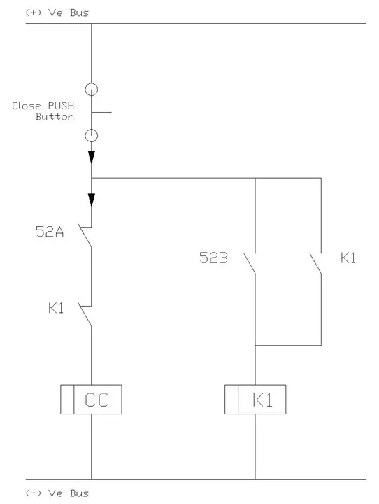
The close button is a momentary push button switch that an operator presses to close the breaker. The circuit breaker has auxiliary contacts that change state based on the breaker position – these are labeled as 52A (closes when breaker is open) and 52B (closes when breaker is closed).
When the breaker is open, the 52A contact is closed, and the 52B contact is open. The anti pumping relay’s contact is in its normal closed position, ready to allow a closing operation.
When the operator presses the close button, current flows through the following path:

The closing coil energizes, and the breaker closes.
As the breaker closes, the 52A contact opens, and the 52B contact closes. This change in auxiliary contact position signals the anti pumping relay (K1) to operate. The anti pumping relay opens its contact in the closing circuit and simultaneously starts a timer or remains latched in this state.
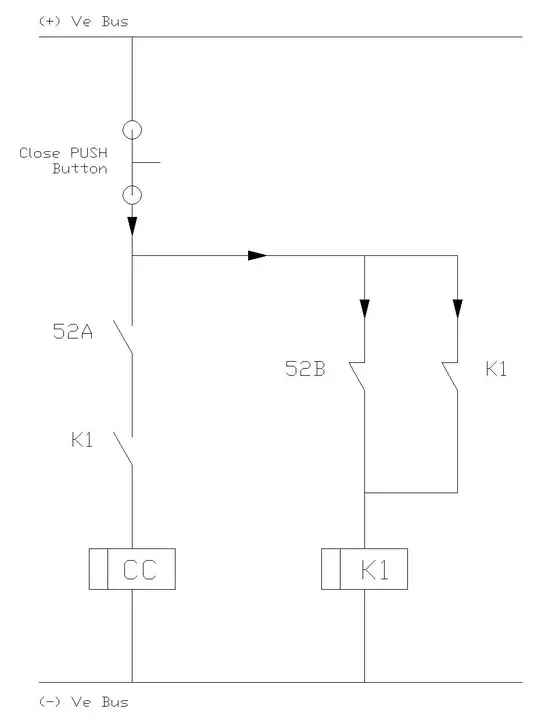
Even if the operator continues holding the close button, no current can flow to the closing coil because the anti pumping relay contact is now open. If the breaker trips due to a fault, the 52A contact closes again, but the breaker still won’t close because the anti pumping relay contact (K1) in the closing circuit remains open.
The anti pumping relay only resets when the close button is released. Once reset, if the operator presses the close button again, the relay allows another closing operation. This ensures controlled, deliberate closing operations rather than uncontrolled pumping.
6. Timing Diagram Analysis
The timing sequence helps visualize how the anti pumping relay coordinates with other control elements. Let’s trace through a scenario where pumping would occur without protection and see how the anti pumping relay prevents it.
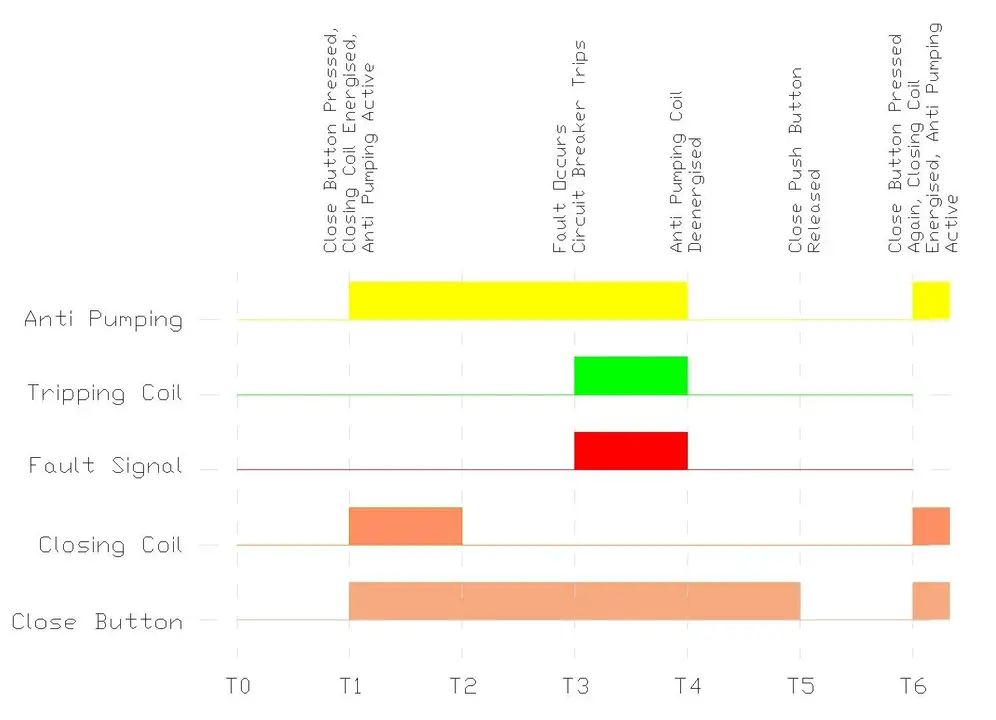
At time T0, the circuit breaker is open, and all systems are at rest. The operator presses and holds the close button at T1. The closing coil energizes, and the breaker begins its closing operation. At T2, approximately 100-200 milliseconds later depending on the breaker type, the breaker reaches the fully closed position.
At T3, a fault occurs on the system, and the protection relay sends a trip signal. The breaker opens at T4, approximately 50-100 milliseconds after the trip command. Here’s where the anti pumping function becomes critical. The close button is still pressed from T1, but the anti pumping relay has already blocked the closing circuit.
Without the anti pumping relay, the breaker would attempt to reclose immediately at T4 when it opens, because the close signal is still present. This would create a pumping cycle with the breaker closing and opening every few hundred milliseconds, causing severe damage.
With the anti pumping relay, the breaker remains open at T4 and beyond, regardless of the close button state. Only when the operator releases the button at T5 and presses it again at T6 will the breaker attempt another closing operation. This controlled behavior protects both the circuit breaker and the power system.
7. Practical Example: Substation Transformer Protection
Let’s consider a real-world scenario to see the anti pumping relay in action. You’re working at a 132/33 kV substation with a 50 MVA transformer. The transformer’s high voltage side is protected by an SF6 circuit breaker with protection relays including differential protection, overcurrent protection, and Buchholz relay.
During a maintenance procedure, a technician is preparing to energize the transformer after an inspection. The technician presses the close button on the high voltage circuit breaker. Unknown to the technician, there’s an internal fault in the transformer winding that wasn’t detected during the visual inspection.
The circuit breaker closes, and immediately the differential protection relay detects the fault and sends a trip signal. The breaker opens within three cycles (approximately 60 milliseconds on a 50 Hz system). Now, here’s the critical moment. The technician, being cautious, was keeping the close button pressed to observe the energization.
Without an anti pumping relay, the circuit breaker would immediately attempt to close again as soon as it opens. Given that the closing time is around 100 milliseconds and the tripping time is 60 milliseconds, the breaker would pump at a rate of about six operations per second. In just two seconds, the breaker would undergo twelve close-open cycles.
Each closing operation would establish the full fault current through the transformer, generating enormous magnetic forces and heat. The circuit breaker contacts would experience severe arcing each time they open under fault current. The SF6 gas would decompose due to repeated arcing, reducing its insulation properties. The operating mechanism’s spring energy would be rapidly consumed and recharged, stressing mechanical components.
With the anti pumping relay installed, the circuit breaker closes once and trips on the fault. Despite the technician holding the close button, the breaker remains open. The technician releases the button, realizes something is wrong, and investigates the cause. The transformer fault is discovered and repaired before any further closing attempts are made. The single fault interruption causes no damage to the circuit breaker, which can continue normal operation for years to come.
8. Installation and Wiring Guidelines
The relay should be mounted in the circuit breaker control panel in a location that’s easily accessible for maintenance but protected from environmental factors.
The relay requires a DC power supply, typically the same voltage used for the circuit breaker control. Ensure that the power supply connections are secure and properly fused. Most anti pumping relays have a dedicated power supply terminal separate from the control contacts.
Follow these simple steps to wire the anti pumping relay circuit correctly:
- Step 1: Connect positive DC bus (+Ve) to one terminal of the close push button.
- Step 2: From the other terminal of PUSH close button, connect to CB normally closed contact 52A. This contact is closed when breaker is open.
- Step 3: From 52A contact, connect to first anti pumping relay contact K1 (normally closed).
- Step 4: From K1 contact, connect to CB Closing Coil (CC).
- Step 5: From CB Closing Coil, connect to negative DC bus (-Ve).
- Step 6: Again From the other terminal of close PUSH button, connect to the CB NO contact 52B and Anti Pumping Relay auxiliary NO contact.
- Step 7: From both CB NO contact 52B and Anti Pumping Relay auxiliary NO contact, connect to the Anti Pumping Relay Coil.
- Step 8: For Anti Pumping Relay coil, connect to negative DC bus (-Ve).
9. Testing and Commissioning
Before putting a circuit breaker with anti pumping protection into service, testing is essential. Start with a visual inspection of all wiring connections to ensure they’re tight and correctly terminated. Check that the relay is properly mounted and that all terminal markings are clear and match the wiring diagram.
Perform a functional test of the anti pumping relay using the following procedure.
- With the circuit breaker open and de-energized from the main system, apply control power to the relay. Verify that the relay’s power indicator illuminates, showing it’s receiving supply voltage.
- Press and hold the close button. The circuit breaker should close normally. While continuing to hold the close button, manually trip the breaker using the trip button. Observe that the breaker opens but does not attempt to reclose despite the close button still being pressed. This confirms the anti pumping function is working correctly.
- Release the close button and press it again. The breaker should close normally, demonstrating that the relay has reset properly. Repeat this test several times to ensure consistent operation.
10. Common Issues and Troubleshooting
10.1 Circuit Breaker Won’t Close
If pressing the close button doesn’t close the circuit breaker, the anti pumping relay could be in a latched state from a previous operation. First, check if the relay’s status indicator shows it’s in the operated position. Release the close button completely and wait a few seconds before trying again.
Verify that the relay is receiving proper power supply voltage. Use a multimeter to measure the DC voltage at the relay’s power terminals. It should match the rated voltage within acceptable limits, typically ±10%. Low voltage can prevent the relay from operating or resetting correctly.
Check the circuit breaker’s auxiliary contacts. If an auxiliary contact is stuck in the wrong position, it may prevent the anti pumping relay from resetting. Manually inspect the auxiliary switch mechanism on the circuit breaker for any mechanical binding or damage.
10.2 Relay Not Blocking Reclosing
If the circuit breaker pumps despite having an anti pumping relay, the relay may not be functioning correctly.
First, verify that the relay contact in the closing circuit is actually operating. You can check this by measuring voltage across the relay contact during a closing operation – it should be near zero when closed and full supply voltage when open.
Examine the auxiliary contact connections to the relay. If these connections are loose or broken, the relay won’t receive proper position feedback from the circuit breaker. The relay needs to know when the breaker has closed to activate its blocking function.
The relay itself may be defective. If you’ve verified all wiring and auxiliary contacts are correct but pumping still occurs, replace the relay with a new one.
11. Conclusion
The anti pumping relay is a small but critical component in circuit breaker control systems. While it may seem like a simple device, its proper function prevents equipment failures and maintains power system stability. Understanding how anti pumping relays work, how to install and maintain them correctly, and how to integrate them with modern protection systems is essential knowledge for electrical engineers working with power systems.