A Capacitive Voltage Transformer, commonly abbreviated as CVT or CCVT is a special device that safely converts extremely high voltages from transmission lines and high voltage busbars into low, manageable voltages that can be measured by meters and understood by protection relays. The traditional voltage transformers uses iron cores and electromagnetic induction. However, CVTs use capacitors and a smart circuit design to achieve this voltage transformation.
In this technical guide, we will discuss everything about Capacitive Voltage Transformer (CVT), including their Working Principle, Circuit Diagram, their Applications in Metering and Protection, Installation, Testing and Commissioning with Practical Examples.
1. What is a Capacitive Voltage Transformer?
A Capacitive Voltage Transformer (CVT), also known as a Coupling Capacitor Voltage Transformer (CCVT), is an instrument transformer used in high-voltage and extra-high-voltage (EHV/UHV) electrical systems. Its primary purpose is to step down the high voltage from transmission lines or Busbars to a standard low voltage typically 110 V or 220 V that can be safely used by metering devices and protection relays.
The term “capacitive” refers to the voltage divider made from capacitors. This is the first stage of voltage reduction in these transformers. CVTs are commonly used in substations with voltage ratings of 132 kV and above where traditional inductive voltage transformers would be too large, expensive, and difficult to install.
The basic principle of a CVT is straightforward: it converts high voltage into low voltage using two main stages.
In the first stage, a series of capacitors divides the high voltage into a more manageable intermediate voltage.
In the second stage, a small auxiliary transformer further reduces this intermediate voltage to the standard secondary voltage needed for meters and relays.
This two-stage approach makes CVTs efficient and practical for extremely high voltage applications. Without CVTs protecting high-voltage transmission lines would be nearly impossible in modern power systems.
2. Working Principle of Capacitive Voltage Transformers
2.1 The Capacitive Voltage Divider Circuit
To understand how a CVT works, you first need to know how capacitors can divide voltage. When two capacitors are connected in series across a voltage source, the voltage distributes between them based on their capacitance values.
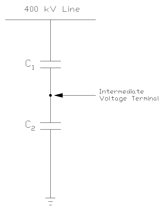
In a CVT, the capacitors are called C1 and C2. The C1 capacitor, positioned near the high-voltage terminal, has a very small capacitance value, often measured in picofarads (pF). The C2 capacitor, positioned closer to the ground, has a much larger capacitance value, typically measured in thousands of picofarads.
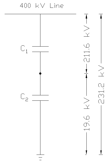
This difference in capacitance values causes the high voltage to divide unevenly, with most of the voltage dropping across C1 and only a smaller voltage appearing at the junction between C1 and C2 as shown in the image above. This intermediate voltage at the junction is then fed to the next stage of the CVT for further reduction.
Example: Suppose a 400 kV transmission line has a CVT connected to it as shown in the figure above. The C1 capacitor might have a capacitance of 100 pF, while C2 has a capacitance of 2000 pF. Using the voltage divider formula, the intermediate voltage at the junction would be approximately 19.6 kV. This is still too high for direct use but is manageable for the next stage of transformation.
The advantage of using capacitive voltage division is that the capacitors themselves do not generate heat during normal operation. The capacitor stack inside a CVT is carefully constructed to ensure proper insulation at the high voltage terminal while maintaining reliable voltage division across all operating conditions.
2.2 The Auxiliary Transformer
After the capacitor voltage divider reduces the voltage to an intermediate level (typically 5 to 20 kV), this intermediate voltage is still too high for meters and relays. To solve this problem, a small auxiliary transformer (also called an intermediate voltage transformer) is connected to the output of the capacitor divider. This transformer is a conventional voltage transformer but much smaller in size and rated for the intermediate voltage, not the original high voltage.
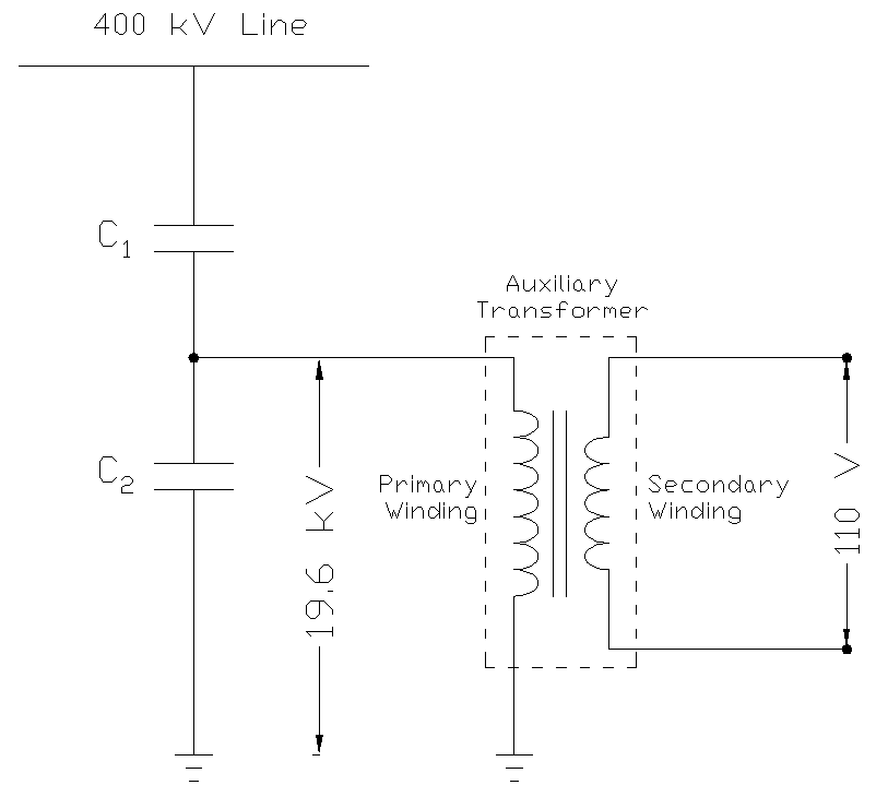
The auxiliary transformer’s primary winding receives the intermediate voltage from the capacitor divider as shown in the image above, and its secondary winding provides the standardized low voltage output, such as 110 V, 220 V, or 110 V/√3. The working principle of this auxiliary transformer is based on Faraday’s Law of Electromagnetic Induction which is the same as in any conventional transformer.
2.3 Compensating Reactor and Phase Angle Correction
When you connect a resistive load (like a meter) to the output of a capacitor voltage divider, the capacitor introduces a phase shift. The output voltage no longer aligns perfectly with the primary voltage; instead, it lags by a certain angle. This phase shift causes errors in protection and metering, especially in distance relays that depend on accurate phase information.
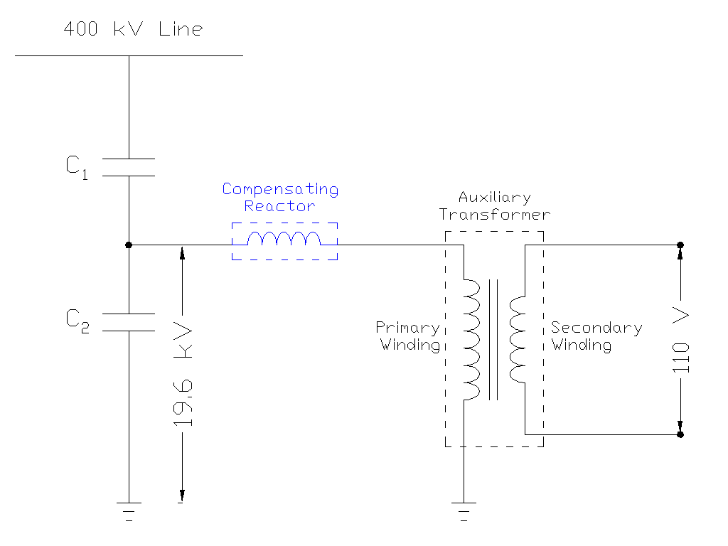
To correct this problem, engineers add a compensating reactor (also called a tuning reactor) in series with the circuit. A reactor is an inductor with controlled inductance. The inductor introduces an equal but opposite phase shift, which cancels out the phase shift caused by the capacitor.
Think of it like balancing: the capacitor pushes the phase in one direction, and the inductor pushes it back. When tuned correctly at the nominal power frequency (50 Hz or 60 Hz), the capacitive reactance and inductive reactance become equal in magnitude but opposite in effect, resulting in a perfectly aligned output voltage.
2.4 Ferroresonance Suppression Circuit
One of the most significant challenges with CVTs is a phenomenon called ferroresonance. This occurs when the capacitive and inductive elements in the CVT interact in unexpected ways during transient conditions, such as when a circuit breaker opens or a fault occurs.
Ferroresonance can cause the voltage inside the CVT to oscillate wildly, reaching several times the normal voltage level, damaging the transformer and causing incorrect operation of protection relays.
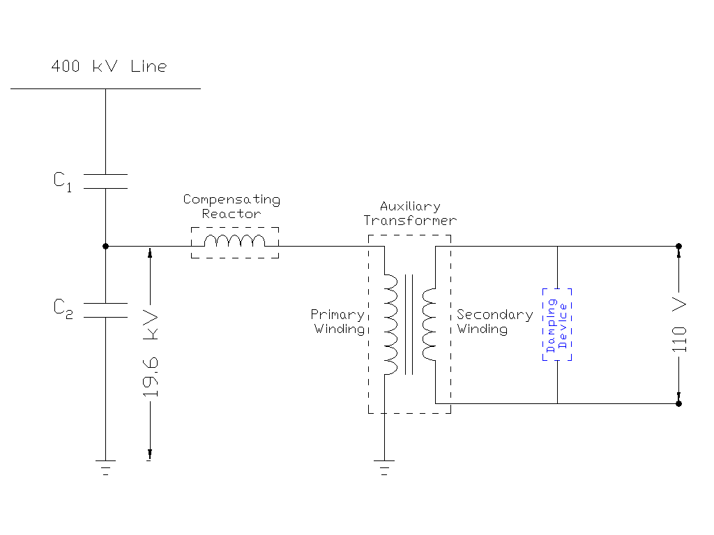
To prevent ferroresonance, CVTs are equipped with a ferroresonance suppression circuit (FSC) or damping circuit. This circuit typically consists of a resistor placed in series with an inductor. The resistor absorbs the energy of the oscillations, converting it to heat and dissipating it. The inductor helps fine-tune the damping to be most effective at preventing the problematic oscillations. Modern CVTs may also use electronic ferroresonance suppression circuits (EFSC) that use electronic control to actively suppress transient overvoltages.
3. Construction and Components of a CVT
3.1 Primary Components
The entire CVT is housed in a metal tank filled with mineral oil for insulation and cooling. At the top of the tank is the high-voltage terminal, which is connected to the transmission line. Below this terminal is the porcelain or composite insulator, which provides mechanical support and electrical insulation. Inside this insulator is the capacitor stack, consisting of hundreds or even thousands of individual capacitor elements stacked in series.
As discussed above, the capacitor stack is divided into two main sections: C1 (the high-voltage capacitor section) and C2 (the intermediate-voltage capacitor section). The junction between C1 and C2 serves as the intermediate voltage terminal, where the output of the capacitive voltage divider is tapped. From this point, the intermediate voltage signal is routed to the electromagnetic unit (EMU), which houses the auxiliary transformer, compensating reactor, and damping circuit.
The electromagnetic unit is mounted at the bottom of the CVT tank and contains all the inductive and resistive components. It is carefully designed and sealed to protect these components from moisture and external environmental conditions.
The primary winding of the auxiliary transformer receives the intermediate voltage, while the secondary winding provides the standardized low-voltage output. The secondary terminals are connected to the metering and protection circuits through individual lead wires.
3.2 Capacitor Stack Design
The capacitor stack is not a single large capacitor but rather a series connection of many small capacitor elements. This design is necessary for two reasons.
First, no single capacitor can be manufactured with both the extremely small capacitance value (in picofarads) required for the C1 section and the ability to withstand the full high voltage across it. By stacking capacitors in series, the voltage is distributed across many elements with each element experiencing only a fraction of the total voltage.
Second, the distributed design provides built-in redundancy. If a single capacitor element fails (short-circuits), the remaining elements in the stack can continue to function, although with reduced performance.
3.3 Auxiliary Transformer and Reactor
The auxiliary transformer inside the electromagnetic unit in a CVT is much smaller and rated for a lower voltage (typically 5 to 20 kV on the primary). It serves the specific purpose of stepping down the intermediate voltage from the capacitive divider to the standard secondary voltage.
The compensating reactor is carefully integrated into the electromagnetic unit, typically wound on the same core as the auxiliary transformer or placed in series with the primary winding. The reactor’s inductance is designed to resonate with the capacitance of the CVT at the nominal power frequency, creating a tuned circuit that provides precise voltage transformation. The inductance value of the reactor is usually between 1 and 10 microhenries for a typical CVT.
The damping circuit, consisting of resistance and inductance, is connected across the secondary terminals or integrated into the electromagnetic unit. This circuit is the “safety net” of the CVT, preventing dangerous transient overvoltages from damaging internal components or affecting connected protection relays. The damping resistance typically ranges from 10 to 100 ohms, depending on the CVT’s design and rating.
4. CVT Applications in Metering
4.1 Voltage Measurement and Energy Billing
One of the primary applications of a CVT is voltage metering. In electrical substations, it is essential to continuously monitor the voltage on transmission lines for several reasons.
First, accurate voltage measurement is necessary for proper operation of the power system. If the voltage at a particular location is too high or too low, it indicates system problems that need to be addressed.
Second, for commercial purposes, the energy supplied must be measured accurately to ensure fair billing and detect theft or illegal tapping.
When a CVT is used for metering, it must provide a secondary voltage that accurately represents the primary voltage. This accuracy is specified by the metering accuracy class. For metering applications, CVTs are designed to meet class 0.2 or class 0.5 accuracy, which means the ratio error should not exceed 0.2% or 0.5%, respectively.
The metering core of a CVT is designed with optimized accuracy over the normal operating voltage range, typically from 90% to 110% of the rated voltage. Due to this the metering core does not saturate at these normal voltages. However, if a fault occurs and the voltage exceeds the normal range, the metering core may saturate. However, this is acceptable because metering is not required during faults.
4.2 Power Quality Monitoring
CVTs are also used for power quality monitoring in modern electrical systems. Power quality refers to the characteristics of the electrical supply, such as voltage magnitude, frequency, harmonics, and voltage transients. Poor power quality can damage sensitive equipment and reduce efficiency. To monitor power quality, instruments called power quality analyzers measure voltage waveforms at the substation level and send this data to monitoring systems.
4.3 Load Flow and System Monitoring
In a power system, it is essential to know the voltage at different locations to understand how power flows through the network. This information is used for system planning, operation, and optimization. CVTs provide voltage inputs to supervisory control and data acquisition (SCADA) systems, which collect voltage data from substations throughout the power network. SCADA systems use this data to create a real-time picture of the system’s operating conditions.
5. CVT Applications in Protection
5.1 Distance Protection and Directional Relays
Distance protection is one of the most important protection schemes in transmission systems. These relays measure the impedance to a fault and trip the circuit breaker if the impedance falls below a set threshold. Distance relays require accurate voltage measurements to calculate impedance correctly. A CVT used for distance protection must not introduce phase errors or amplitude errors, as even small errors can cause the relay to misidentify the fault location or fail to detect a fault.
For distance protection applications, CVTs must meet protection accuracy class 3P or 6P, where “P” stands for protection. The number (3 or 6) indicates the maximum allowable ratio error in percent. A class 3P CVT has a maximum ratio error of ±3%, while a class 6P CVT has a maximum ratio error of ±6%. The tolerance is higher than for metering (class 0.2) because protection relays can tolerate larger measurement errors and still operate correctly.
5.2 Overvoltage and Under-voltage Protection
While distance protection is the primary application, CVTs also provide voltage inputs for simpler protection schemes such as overvoltage protection and under-voltage protection. Overvoltage protection monitors the secondary voltage output of the CVT and issues a signal to trip the circuit breaker if the voltage exceeds a preset threshold, typically set at 110% to 120% of the rated voltage.
Under-voltage protection operates on the opposite principle. It monitors for abnormally low voltages and may trigger load-shedding schemes or alert operators to system problems. Under-voltage conditions often indicate a loss of generation or major transmission line outages, and quick detection and response are important for system stability.
These protection schemes are less sensitive to small measurement errors compared to distance protection, so they can use CVTs with lower accuracy classes. However, the voltage input from the CVT must still be reliable and representative of the actual system conditions to ensure proper protection operation.
5.3 Voltage Unbalance and Phase Sequence Detection
In three-phase power systems, ideally all three phases should have equal voltage magnitude and be equally spaced in phase (120 degrees apart). However, unbalanced loads and unsymmetrical faults can cause the three phases to have different magnitudes and phase angles. This voltage unbalance can damage equipment and reduce system reliability.
Protection relays that detect voltage unbalance use voltage inputs from three CVTs (one on each phase) to calculate the positive sequence, negative sequence, and zero sequence voltage components. These components are used to identify and quantify unbalance conditions.
6. CVT Accuracy Classes and Specifications
6.1 Metering Accuracy Classes
The IEC 61869 standard and various national standards (such as IS 2705 in India and IEEE standards in North America) define accuracy classes for CVTs used in metering. These standards specify the maximum allowable error in the voltage ratio and phase displacement error under specified conditions.
For metering CVTs, the standard accuracy classes are:
- Class 0.1: Maximum ratio error of ±0.1% at rated voltage and rated burden. This is the highest accuracy class and is used in applications where measurement precision is paramount.
- Class 0.2: Maximum ratio error of ±0.2% at rated voltage and rated burden. This is the most common metering class used in utility substations for revenue metering.
- Class 0.5: Maximum ratio error of ±0.5% at rated voltage and rated burden. This class is acceptable for many applications where slightly lower accuracy is tolerable.
- Class 1: Maximum ratio error of ±1% at rated voltage and rated burden. This class is rarely used in modern substations.
6.2 Protection Accuracy Classes
For protection applications, accuracy classes are defined differently. The protection classes specify the maximum error at high voltage levels (typically at several times the rated voltage) and include a composite error, which accounts for both ratio error and phase displacement error.
The standard protection accuracy classes are:
- Class 3P: Maximum composite error of ±3% at the accuracy limit factor times the rated voltage. This class is used for sensitive protection schemes such as distance protection.
- Class 6P: Maximum composite error of ±6% at the accuracy limit factor times the rated voltage. This class is used for less sensitive protection schemes.
The accuracy limit factor (ALF) defines the voltage level at which the accuracy specification applies. For example, a class 3P protection CVT with an ALF of 1.2 will maintain ±3% accuracy at 1.2 times the rated voltage.
Example: A 400 kV class 3P protection CVT will maintain ±3% accuracy up to 400 kV × 1.2 = 480 kV. If a transient overvoltage causes the voltage to exceed 480 kV, the accuracy specification is no longer guaranteed, but the CVT should not fail.
6.3 Secondary Burden and Classification
The secondary burden is the total impedance connected to the secondary of the CVT. This includes the impedance of the protection relays, metering devices, wiring, and any other connected instruments. Burden is measured in volt-amperes (VA) or ohms (Ω).
CVTs are rated with a burden designation, such as Y, Z, ZZ, or ZZZ, which specifies the maximum burden for which the CVT will maintain its accuracy class:
- Y: Maximum burden of 75 VA
- Z: Maximum burden of 200 VA
- ZZ: Maximum burden of 400 VA
- ZZZ: Maximum burden of 800 VA
When selecting a CVT for a substation, it is essential to calculate the total secondary burden and ensure that the CVT’s burden rating is sufficient. The total burden includes the lead resistance, the impedance of the connected relays, and the impedance of the metering devices.
Example: A substation has three protection relays (each with 0.3 VA burden) and three metering devices (each with 0.5 VA burden) connected to a protection CVT through 100 meters of wire (2.5 mm² copper). The lead burden is calculated as 0.5 Ω (approximately 2.5 VA for 110 V secondary). The total burden is approximately 0.3 + 0.3 + 0.3 + 0.5 + 0.5 + 0.5 + 2.5 = 5.4 VA. A CVT with burden rating Y (75 VA) would be more than sufficient for this application.
7. CVT in Power Line Carrier Communication (PLCC)
7.1 Dual Function
One of the unique advantages of CVTs is their ability to serve a dual function: voltage transformation for metering and protection, and signal coupling for power line carrier communication (PLCC). PLCC is a communication system that uses the power transmission line itself as a communication channel, allowing voice, data, and control signals to be transmitted between substations without requiring separate fiber optic cables.
The capacitor stack inside the CVT naturally acts as a coupling element for high-frequency signals. The same capacitors that divide the low-frequency power voltage (50 or 60 Hz) have relatively low impedance to high-frequency signals (30 to 500 kHz), allowing these signals to pass through to the PLCC equipment. This means that a single CVT can perform both the voltage transformation function and the coupling function that would otherwise require separate equipment.
When a CVT is used with PLCC equipment, it is sometimes referred to as a Coupling Capacitor Voltage Transformer (CCVT), for its dual role. The CCVT eliminates the need for separate coupling capacitors, saving both cost and installation space in the substation.
7.2 Wave Trap and Line Tuner Integration
To enable PLCC communication on a transmission line, additional equipment is required. The wave trap (also called line trap) is a parallel resonant circuit installed in series with the transmission line at the substation. The wave trap is tuned to block the high-frequency communication signals from flowing into the substation bus.
The line tuner is another component that works in conjunction with the CVT and wave trap. The line tuner is a resonant circuit that matches the impedance of the PLCC transmitter and receiver to the characteristic impedance of the transmission line for efficient transfer of communication signals. Together, the CVT, wave trap, line tuner, and PLCC equipment form a complete communication system.
8. CVT vs. Inductive Voltage Transformers (IVTs)
In electrical substations, two main types of voltage transformers are used: inductive voltage transformers (IVTs), also called electromagnetic voltage transformers (EMVTs), and capacitive voltage transformers (CVTs). Each type has distinct characteristics and applications.
IVTs use a conventional transformer design with a laminated iron core, a primary winding connected to the high voltage circuit, and secondary winding(s) providing low voltage outputs. IVTs operate on the principle of electromagnetic induction, the same principle as power transformers. IVTs are suitable for voltage levels up to about 33 kV and are commonly used in medium voltage (MV) substations.
The following table summarizes the key differences between IVTs and CVTs:
| Parameter | IVT (Electromagnetic VT) | CVT (Capacitive VT) |
|---|---|---|
| Suitable Voltage Range | Up to 33 kV | 132 kV and above |
| Primary Principle | Electromagnetic induction | Capacitive voltage division + induction |
| Physical Size & Weight | Larger and heavier | Compact and lightweight |
| Cost | Less expensive at lower voltages | More economical at higher voltages |
| Accuracy for Metering | Higher (typically class 0.1-0.2) | Good (class 0.2-0.5) |
| Transient Response | Better transient response | May have transients; requires damping |
| PLCC Capability | Requires separate coupling capacitor | Integrated coupling capability (CCVT) |
| Maintenance | Simpler, conventional design | More complex; requires specialized knowledge |
| Insulation Requirements | Requires large insulation distance | Compact insulation design |
8.1 Advantages of CVTs for EHV Applications
As transmission voltages have increased to 245 kV, 400 kV, 500 kV, and beyond, CVTs have become the dominant choice for voltage transformation.
The advantages of CVTs in EHV applications are compelling:
- Cost Advantage: An inductive VT designed for 400 kV would require a massive laminated iron core and extensive insulation, making it prohibitively expensive. In contrast, a CVT uses a much smaller electromagnetic unit, resulting in total cost savings of 30% to 50% compared to an equivalent IVT.
- Size and Weight Advantage: A typical 400 kV IVT might be 3 to 4 meters tall and weigh 1000 to 1500 kg, requiring substantial foundation support and substation space. A comparable CVT might be 2 to 3 meters tall and weigh 300 to 500 kg, saving substation space and reducing installation costs.
- Integrated PLCC Capability: CVTs naturally provide coupling for PLCC without requiring additional equipment, whereas IVTs require separate coupling capacitors and associated hardware.
- Flexibility: CVTs can be easily retrofit with electronic enhancements, such as electronic ferroresonance suppression circuits or transient overvoltage compensation algorithms, to improve performance. IVTs are more limited in this regard due to their conventional design.
8.2 Disadvantages and Limitations of CVTs
Despite their many advantages, CVTs do have some disadvantages and limitations that must be considered:
- Transient Sensitivity: CVTs are more sensitive to transients than IVTs. A fault event that would cause only mild oscillations in an IVT might cause significant transients in a CVT. This is why damping circuits and advanced protection schemes are essential for CVT-based protection systems.
- Complexity: CVT design and maintenance require specialized knowledge and equipment. Troubleshooting a malfunctioning CVT is more complex than for a simple IVT.
- Risk of Ferroresonance: The potential for ferroresonance in CVTs is a significant concern that requires careful design and testing. While ferroresonance suppression circuits are now standard, this is an additional complexity not found in simple IVTs.
- Burden Sensitivity: The accuracy of a CVT is more sensitive to secondary burden than an IVT.
- Maintenance and Testing: CVT maintenance and insulation testing (such as dissipation factor testing) are more involved than for IVTs and require specialized equipment and expertise.
9. Selection of CVTs
When designing a substation, selecting the appropriate CVT is an important task. The selection process involves several steps:
- Determine the voltage rating: The CVT’s primary voltage rating must be equal to or higher than the system voltage. For a 400 kV system, a 420 kV rated CVT is typically selected.
- Determine the number of cores and accuracy classes: For applications requiring both metering and protection, a CVT with separate cores is typically used. Each core has its own accuracy class. For example, a 400 kV CVT might have a metering core with class 0.2 accuracy and a protection core with class 3P accuracy.
- Calculate the secondary burden: All instruments and relays connected to the CVT secondary must be listed, and their impedances must be summed. This total burden must not exceed the CVT’s burden rating. If the calculated burden exceeds the CVT’s rating, a CVT with a higher burden rating must be selected, or the number of connected instruments must be reduced.
- Determine if PLCC capability is required: If power line carrier communication is needed, a CCVT with integrated coupling capability should be selected. If PLCC is not required, a standard CVT without coupling capability can be used at lower cost.
- Select the damping circuit type: Modern CVTs should have either a passive ferroresonance suppression circuit (PFSC) or an electronic suppression circuit (EFSC).
Example of CVT selection: A 400 kV transmission substation requires a new CVT for a bay with distance protection relays and revenue metering. The required specifications would be: 400 kV primary rating, two cores (0.2 metering + 3P protection), burden rating Z (200 VA) to accommodate the three distance relays and three metering devices, and an electronic ferroresonance suppression circuit for reliable distance relay operation during transients.
10. Installation and Commissioning
The CVT must be installed on the correct phase of the transmission line, with the high-voltage terminal securely connected to the line and the neutral connected to ground. The secondary terminals must be clearly labeled to indicate which core (metering or protection) each terminal belongs to, to prevent incorrect connections during commissioning.
During commissioning, several tests must be performed:
- Visual Inspection: Check for any damage to the CVT during shipping and installation. Inspect the porcelain insulator for cracks or damage. Check that all connections are tight and properly identified.
- Metering Tests: Verify that the secondary voltage is within acceptable limits under normal operating conditions. Use a precision voltmeter to measure the secondary voltage and compare it with the expected value. Verify that the metering core accuracy meets the specified class.
- Protection Tests: Verify that the protection relays respond correctly to secondary voltage from the protection core. Inject a secondary voltage into the CVT and verify that the relays trip at the expected settings.
- Transient Tests: If an electronic damping circuit is present, verify that it is functioning correctly by injecting transient signals and observing the damping behavior.
After successful commissioning, periodic maintenance and testing must be performed for continued reliable operation.
11. Difference Between CVT and CCVT
Capacitive Voltage Transformer (CVT) and Coupling Capacitor Voltage Transformer (CCVT) are both essential instruments in high-voltage power systems, but they serve different purposes and have distinct configurations. Let’s have a look at the key differences between CVT and CCVT.
11.1 CVT vs CCVT
| Comparison Parameter | CVT (Capacitive Voltage Transformer) | CCVT (Coupling Capacitor Voltage Transformer) |
|---|---|---|
| Basic Definition | A voltage transformer that combines a capacitive voltage divider with an electromagnetic voltage transformer to step down high voltage for metering and protection | A CVT with an integrated coupling unit (PLCC equipment) that enables power line carrier communication in addition to voltage transformation |
| Primary Function | Step down high voltage (132 kV to 1200 kV) to standard secondary voltage (110 V or 220 V) | Same as CVT: Step down high voltage to standard secondary voltage |
| Secondary/Auxiliary Function | Optional: Can be used with PLCC if HF terminal is connected to separate coupling unit | Mandatory: Provides coupling path for PLCC signals using integrated coupling unit or HF terminal connection |
| Main Components | 1) Capacitive voltage divider (C1, C2) 2) Compensating reactor 3) Auxiliary transformer 4) Damping circuit 5) Secondary windings (metering & protection) | All CVT components PLUS: 6) PLCC coupling unit or carrier coupling terminal 7) Integrated or dedicated HF (High Frequency) terminal |
| PLCC Capability | Can support PLCC if external coupling equipment is added to HF terminal | Designed with integrated PLCC capability; ready for immediate coupling to PLCC equipment |
| Wave Trap Requirement | Wave trap is used if PLCC communication is planned | Wave trap is typically installed to block high-frequency signals from entering the substation bus |
| Carrier Frequency Range | N/A (not designed for PLCC unless externally coupled) | 40 kHz to 500 kHz (optimized for PLCC communication) |
| High Frequency (HF) Terminal | May have HF terminal but it is kept grounded when not in use | HF terminal is active and ready for PLCC equipment connection; integral to the design |
| Cost | Lower cost (no PLCC coupling unit integrated) | Higher cost due to integrated PLCC coupling unit and additional components |
| Installation Flexibility | Can be installed in any substation; PLCC can be retrofitted later if needed | Best for substations where PLCC is planned or already in use |
| Typical Applications | 1) Basic metering applications 2) Protection relay voltage input 3) Power quality monitoring 4) Substations without PLCC requirement | 1) Transmission line protection with pilot schemes 2) Remote substations needing PLCC communication 3) Integrated communication and control systems 4) Long transmission line protection |
| Maintenance Complexity | Simpler maintenance; standard CVT testing procedures | More complex; requires knowledge of both voltage transformation and PLCC coupling circuits |
| Testing Requirements | 1) Standard CVT tests (dissipation factor, capacitance) 2) Transient response testing 3) Accuracy verification | All CVT tests PLUS: 4) PLCC coupling efficiency testing 5) HF terminal impedance verification 6) Carrier signal attenuation testing |
| Accuracy Classes | Metering: Class 0.2, 0.5 Protection: Class 3P, 6P | Same accuracy classes as CVT (PLCC coupling does not affect voltage transformation accuracy) |
| Future Flexibility | Can add PLCC capability later (retrofit possible) | Not easily downgradable; designed specifically for PLCC |
| Recommended for Substations | ✓ Distribution substations ✓ Local substations without remote control ✓ Budget-conscious utilities ✓ Systems without pilot protection | ✓ Transmission substations ✓ Remote substations requiring communication ✓ Lines requiring selective tele-protection ✓ Modern utilities with fiber backup or PLCC backup |
12. Conclusion
Capacitive Voltage Transformers (CVTs) are indispensable components in modern high-voltage electrical power systems, serving important functions in both metering and protection. By utilizing capacitive voltage division combined with an auxiliary transformer and compensating reactor, CVTs efficiently and cost-effectively transform extremely high voltages into low, safe, and measurable voltages. Their integration of voltage transformation with power line carrier communication capability adds further value in remote or fiber-free substations.