An SF6 circuit breaker is one of the most important protective devices used in modern power systems. It is designed to safely interrupt electrical circuits during normal operation and especially during fault conditions.
The term “SF6” refers to sulfur hexafluoride gas, which is a remarkable insulating and arc-extinguishing medium that has revolutionized the electrical industry since its introduction in high-voltage applications. Compared to the traditional circuit breakers that relied on oil or air insulation, SF6 circuit breakers offer superior performance, compact design, and excellent reliability.
In this technical guide, we will discuss every aspect of SF6 circuit breakers, from basic working principles to complex component including properties of SF6 gas, construction, tripping mechanism, closing mechanism, spring charging mechanism, control circuit, maintenance, Testing & Commissioning.
1. Importance of Circuit Breaker
Before discussing about the SF6 circuit breaker in detail, let’s first understand what a circuit breaker does and why it’s necessary in power systems.
The importance of circuit breakers in electrical systems cannot be brush aside. A circuit breaker is an automatic switching device that can open or close an electrical circuit under normal operation and can automatically interrupt the circuit when a fault current exceeds a predetermined threshold value. The circuit breaker detects abnormal condition through protective relays like overcurrent relay, distance relay, differential relay, etc., and interrupts the current within milliseconds to protect the entire system.
Without a circuit breaker, this fault current would damage transformers, generators, cables, and other equipment by causing fires and endangering personnel.
Every circuit breaker, regardless of its insulation medium or voltage rating, must perform four essential functions:
- Normal switching operation – The breaker can be manually opened and closed to connect or disconnect circuits during planned maintenance or load changes.
- Fault detection – Protective relays connected to the breaker detect abnormal conditions such as overcurrent, overvoltage, or ground faults.
- Fast tripping – When a fault is detected, the breaker must open very quickly, typically within 30 to 100 milliseconds, depending on the system requirements.
- Arc suppression – When the contacts separate, an electric arc forms between them, and this arc must be rapidly extinguished to prevent continued current flow and damage to the contacts.
2. Why SF6 Gas is Superior for Circuit Breaker Applications?
The insulation medium used inside the circuit breaker must perform two competing tasks simultaneously.
First, it must insulate the conductors from each other and from ground to prevent unwanted current leakage between the circuit breaker phases.
Second, it must help extinguish the arc that forms when the contacts separate to allow the circuit to be safely interrupted.
SF6 gas is exceptional because it excels at both these tasks far better than oil, air, or vacuum.
2.1 Exceptional Arc-Extinguishing Properties
SF6 gas possesses extraordinary arc-extinguishing capability that is approximately 100 times better than air at the same pressure.
During interruption, an electric arc forms between the circuit breaker contacts. This arc is an ionized gas column carrying the fault current at extremely high temperatures. The arc must be cooled and de-ionized to break the conduction path. SF6 achieves this through negative ion formation.
When SF6 molecules are exposed to the thermal and electrical energy of the arc, they attach free electrons from the plasma to form negative ions such as SF6⁻ and SF5⁻. These heavy negative ions move much slower than free electrons. This reduces the conductivity of the gas and thus rapidly extinguishing the arc current.
2.2 Superior Insulating Strength
In addition to arc suppression, SF6 gas provides outstanding dielectric strength. It resists electrical breakdown and can safely withstand high voltages without allowing current to flow between conductors.
The dielectric strength of SF6 at atmospheric pressure is approximately 2.4 times greater than air. At higher pressures (typically 4 to 5 bar in commercial circuit breakers), the insulation capability increases proportionally.
This superior insulation allows circuit breaker manufacturers to design compact equipment that can handle up to 765 kV transmission voltages.
2.3 Environmental and Safety Considerations
While SF6 gas offers exceptional electrical performance, it is important to note that SF6 is a potent greenhouse gas with a global warming potential (GWP) approximately 23,500 times that of carbon dioxide.
However, when handled properly with good maintenance practices and leak detection, SF6 circuit breakers remain the industry standard because their superior performance enables more reliable and safer power systems.
3. Main Components of an SF6 Circuit Breaker
An SF6 circuit breaker is a complex assembly of many precisely engineered components working in perfect coordination. Let’s discuss some of the main components of an SF6 Circuit Breaker.
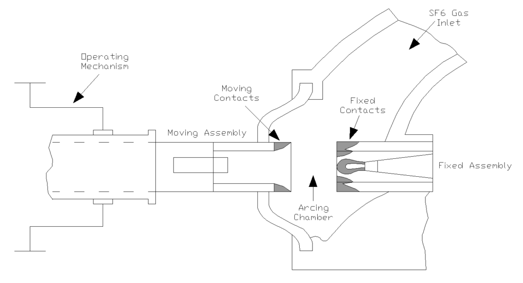
3.1 Fixed and Moving Contacts
The fixed contact and moving contact form the interrupting unit of the circuit breaker. The fixed contact is mounted on the stationary part of the breaker frame and carries the incoming current from the power system. The moving contact is attached to a movable rod that can separate from the fixed contact when the breaker opens.
Both contacts are typically manufactured from copper-tungsten composite material because it offers excellent electrical conductivity, high arc erosion resistance, and mechanical strength. When the breaker is closed, these contacts touch each other with significant contact pressure to ensure low electrical resistance and minimal heat generation during normal current flow.
During the opening operation, the moving contact is pulled away from the fixed contact by the electromagnetic repulsion force from the opening coil combined with the spring release mechanism. As the gap increases, an electric arc forms between the contacts, carrying the circuit current. The arc erodes the contact surfaces, creating a small amount of metal vapor and roughening the contact surfaces.
A single opening operation might remove only micrograms of contact material, but after many switching operations (typically 1,000 to 10,000 cycles depending on the duty), the contacts must be inspected or replaced to maintain optimal breaking capacity.
3.2 Arc Extinguishing Chamber (Interrupter)
The arc extinguishing chamber is the heart of the circuit breaker where the arc is actually created and then suppressed. This chamber contains several carefully designed internal structures:
The nozzle is a specially shaped passage through which the SF6 gas is forced during the opening operation. As the moving contact separates, a puffer piston (described below) compresses the SF6 gas, forcing it at high velocity through the nozzle and directly across the arc column. This high-velocity gas stream cools the arc, removes ionized particles, and pushes them away from the contact gap to prevent arc re-ignition.
The puffer piston is directly attached to the moving contact assembly. As the moving contact travels downward during opening, the puffer piston moves upward relative to the fixed contact structure. This compresses the SF6 gas trapped below the moving contact. This compression creates pressure that forces the gas through the nozzle with considerable velocity.
3.3 Spring Charging Mechanism
The spring charging system stores mechanical energy that will be released when the breaker closes. In most SF6 circuit breakers, a large helical spring is compressed and latched in the charged position by a catch mechanism. This stored spring energy provides the force needed to drive the moving contact from the open position back to the closed position when the closing command is given.
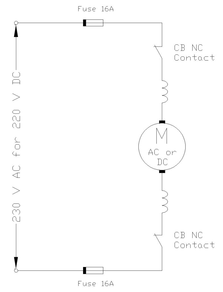
The spring charging can be done manually using a hand crank lever (for smaller breakers) or automatically using an electric motor driven by the station DC or AC power supply. A charging indicator on the breaker shows whether the spring is charged or discharged.
Without sufficient spring energy, the closing operation might fail which may leave the breaker in a dangerous intermediate position where the contacts are not fully separated or fully closed.
3.4 Operating Mechanism
The operating mechanism is the collection of mechanical linkages, latches, and guides that convert the stored spring energy into controlled motion of the moving contact assembly. When the spring is released by the catch mechanism, it pushes a rotating shaft or sliding rod that transfers the motion to the moving contact assembly through a series of mechanical linkages.
The operating mechanism also includes overtravel design, which means the closing motion continues for a small distance past the point where the contacts first touch each other. This overtravel ensures that the contacts are pressed together with the correct contact force, which is typically between 1,000 and 5,000 Newtons depending on the contact size and breaker rating.
3.5 The Trip Coil
The trip coil (also called the opening coil or tripping solenoid) is an electromagnetic device that initiates the opening operation of the circuit breaker. It consists of a coil of copper wire wound around an iron core, similar to any electromagnetic relay. When the protective relay detects a fault condition and sends an electrical signal to energize the trip coil, current flows through the coil windings. This current creates a magnetic field that pulls on the iron armature attached to the breaker’s latch mechanism.
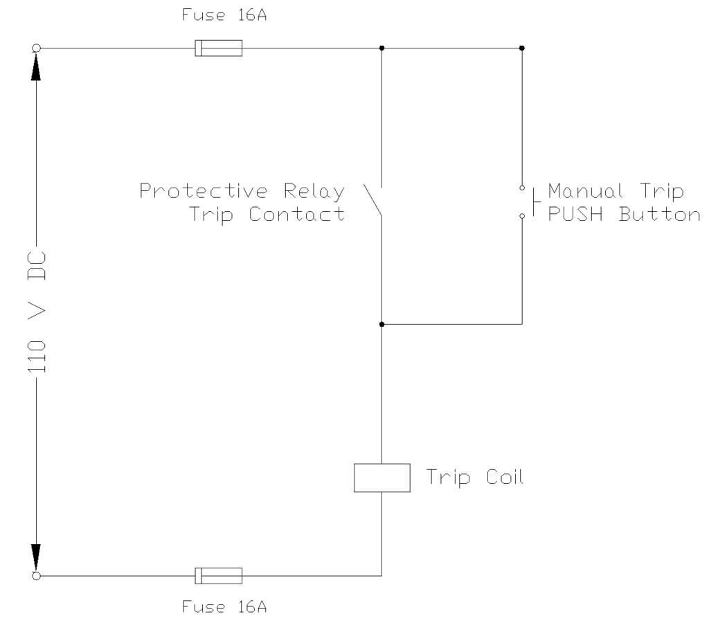
Once the trip coil is energized, this magnetic pull releases the latch that was holding the moving contact in the closed position against the spring pressure. Immediately upon latch release, the spring pressure pushes the moving contact downward (in a typical vertical-break design), rapidly separating it from the fixed contact. The trip coil does not need to provide the actual opening force; it only needs to release the mechanical latch. The tripping time is typically within 20 milliseconds.
The trip coil is energized by the secondary circuit of a protective relay. Typically, the relay is energized from the secondary of a current transformer (CT) that monitors the phase currents, or from the secondary of a potential transformer (PT) that monitors voltage.
3.6 The Closing Coil
The closing coil (also called the closing solenoid) is structurally very similar to the trip coil but serves the opposite function: it initiates the closing operation rather than the opening operation.
When an operator wants to close the breaker, the closing coil is energized, which pulls on an armature that releases the spring catch mechanism. Releasing the spring catch allows the compressed spring to push the moving contact assembly upward toward the fixed contact. As the contacts approach each other, they accelerate due to the spring force and often reach contact speeds between 2 and 5 meters per second.
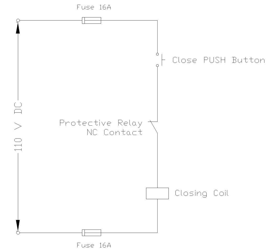
Unlike the trip coil, which must act instantaneously upon fault detection, the closing coil receives its energization signal from the operator or from an automatic control system. The closing action is not as time-critical as the opening action, but it must still be reliable. Closing time is typically 1 to 3 seconds, compared to opening time of only 30 to 100 milliseconds.
3.7 The Control Circuit
The control circuit is an essential system that coordinates the trip coil, closing coil, protective relays, and operator commands into a controlled sequence. A properly designed control circuit ensures that the circuit breaker cannot be damaged by simultaneous closing and tripping commands, that the operator has the information needed to safely operate the breaker, and that the protective relays can reliably trip the breaker when faults occur.
A typical SF6 circuit breaker control circuit includes the following elements:
- Spring charge monitoring involves a position switch that checks whether the spring is fully charged. The control circuit prevents the operator from attempting to close the breaker if the spring is not charged.
- Manual control switches allow the operator to command the breaker to open or close from a local control panel. These switches are interlocked so that accidentally pressing both the “close” and “open” buttons simultaneously cannot cause simultaneous energization of both coils. Additionally, the control circuit prevents closing commands if the breaker is already closed, and prevents opening commands if the breaker is already open.
- Protective relay coordination is handled through auxiliary contacts on the protective relays. When a protective relay detects a fault, it closes its trip contacts, completing a circuit that energizes the trip coil. The control circuit ensures that the trip command takes priority over any closing command.
- Position indication is provided by position switches that sense when the moving contact is fully closed and when it is fully open. These position indications are transmitted to the control room through copper wires or optical fiber to verify the breaker status and detect any failure of the breaker to complete its operation.
- DC power supply comes from the station battery system (typically 110 or 220 volts DC).
4. The Arc Extinguishing Process
When the moving contact begins to separate from the fixed contact, the contact gap increases from zero to several millimeters. At the moment of separation, the moving contact is carrying the full fault current, and this current must flow through the increasing air gap between the contacts.
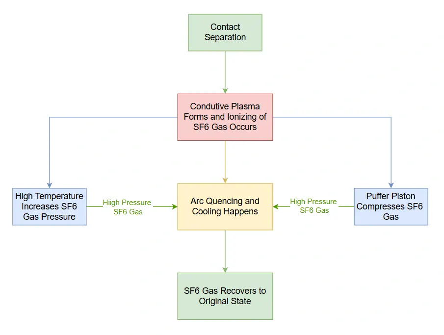
Initially, at the moment of contact separation, the gap is extremely small (less than 1 micrometer), and the electric field strength at the gap is enormous often exceeding millions of volts per meter. At this field strength, the SF6 gas molecules are ionized and a conductive plasma forms. This allows the current to continue flowing across the gap.
Arc pressure development occurs as the arc heats the SF6 gas to extremely high temperatures. The heated gas expands rapidly, creating pressure waves that travel outward from the arc column. In a puffer-type breaker design, the puffer piston motion further compresses the gas, creating even higher pressure that forces the gas to flow through the nozzle and across the arc column at high velocity.
Arc cooling and de-ionization happens as the high-velocity SF6 gas stream removes heat and ionized particles from the arc column. As the ions are swept away and the arc temperature drops below the ionization temperature, the gas molecules recombine with free electrons, re-forming neutral SF6 molecules. The conductivity of the gas drops as the ion population decreases. Meanwhile, the circuit current decreases naturally as the AC sine wave passes through zero.
Current zero is the moment when the AC fault current naturally decreases to zero amperes. At this instant, the ions and free electrons in the arc are at their minimum concentration because the arc power has dropped to nearly zero. The voltage difference between the contacts begins to increase (this is called the transient recovery voltage or TRV), but if the gas has recovered sufficient dielectric strength before the TRV reaches peak value, the gas will not break down and the arc will not re-ignite. This is where SF6 excels due to its superior insulation recovery and ion de-ionization rate are faster than any other commonly available gas.
Post-arc recovery continues for several milliseconds after the current zero as residual ions continue to recombine and the SF6 gas fully recovers its insulating properties. By the time the next half-cycle of the AC voltage begins, the gas has regained full dielectric strength, and no further arcing occurs. The circuit is safely interrupted.
5. SF6 Circuit Breaker Advantages and Disadvantages
5.1 Advantages
- Excellent arc suppression – SF6 circuit breakers can safely interrupt fault currents far higher than air or vacuum circuit breakers of similar size
- Compact design – Because SF6 has superior insulation and arc suppression properties, circuit breakers can be much smaller than equivalent air-insulated designs
- High reliability – SF6 breakers have proven track records with mean-time-between-failures measured in decades
- Low maintenance – Well-sealed SF6 breakers require minimal maintenance and can operate for 15-20 years between major overhauls
- Wide operating temperature range – Modern SF6 breakers operate reliably from -40°C to +50°C, making them suitable for harsh climates
- High voltage capability – SF6 breakers are economically available for voltages up to 765 kV and even higher
- Excellent switching capability for capacitive loads – SF6 breakers can safely switch circuits containing capacitors without the repetitive re-ignition problems that sometimes affect other breaker types
5.2 Disadvantages
- Environmental impact – SF6 is a potent greenhouse gas; leakage must be minimized through proper maintenance and periodic inspection
- Contact erosion – Arc erosion of contacts requires periodic maintenance and eventual contact replacement
- Complexity – SF6 breakers are more complex than some alternative breaker types and require specialized maintenance training
- Higher initial cost – The sophisticated design and manufacturing process makes SF6 breakers more expensive than some alternative types
- Gas recovery equipment – Proper maintenance of SF6 breakers requires specialized gas recovery and recycling equipment
6. Maintenance and Testing of SF6 Circuit Breakers
6.1 SF6 Gas Analysis
SF6 gas analysis (or Dissolved Gas Analysis) is an important diagnostic test that evaluates the quality and purity of the sulfur hexafluoride gas inside the circuit breaker. During arc interruption operations, the extreme temperatures cause partial decomposition of SF6, producing byproducts like sulfur dioxide, hydrogen fluoride, and other compounds. These decomposition products can be toxic, corrosive, and reduce the gas’s dielectric strength.
The test involves extracting a gas sample from the breaker using specialized sampling equipment and analyzing it using gas chromatography or other analytical methods. High levels of decomposition products indicate heavy arcing activity and may require gas filtering or replacement.
Regular gas analysis helps predict maintenance needs and ensures the breaker maintains its full interrupting capability. Most standards recommend gas analysis after major fault interruptions or every 3-5 years during routine maintenance.
6.2 SF6 Gas Dew Point Test
The dew point test determines the moisture content in SF6 gas. It is important because water contamination severely degrades both the dielectric strength and arc-quenching properties of the gas. Moisture can enter the breaker through leaking seals, during gas filling operations, or from hygroscopic materials inside the equipment. When moisture combines with SF6 decomposition products, it forms corrosive acids that attack metal components and insulating materials.
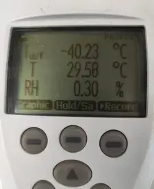
The test measures the temperature at which moisture in the gas begins to condense. This is expressed as dew point in degrees Celsius at atmospheric pressure. Acceptable dew point values typically range from -40°C to -50°C, depending on the breaker’s rated voltage and manufacturer specifications.
6.3 Contact Timing Test
Contact timing test, also called circuit breaker timing test, measures the precise timing characteristics of the breaker’s opening and closing operations. This test verifies that the breaker operates within manufacturer specifications and ensures all three poles of a three-phase breaker operate synchronously.
Timing test can be done using a circuit breaker analyzer to measure parameters including opening time, closing time, arcing time, and pole discrepancy.
For example, a typical 132 kV SF6 breaker might have an opening time specification of 40-50 milliseconds with maximum pole discrepancy of 3 milliseconds. Deviations from specified timings indicate mechanical problems such as worn bearings, inadequate lubrication, weakened springs, or damper issues.
The test should be performed during commissioning, after major maintenance, and periodically as part of the maintenance schedule. Trending timing measurements over years helps identify gradual mechanical deterioration before it causes failure.
6.4 Contact Resistance Test (CRM and DCRM)
Contact Resistance Measurement (CRM) and Dynamic Contact Resistance Measurement (DCRM) detect contact erosion, oxidation, and mechanical deterioration by measuring electrical resistance across the circuit breaker contacts.
Static CRM uses a bridge method with 100 amperes DC current injected through the closed contacts and measures voltage drop to calculate resistance value using Ohm’s law. Normal contact resistance is typically 50-150 microohms (μΩ).
Dynamic CRM (DCRM), also called Dynamic Resistance Measurement (DRM), measures contact resistance during the opening stroke as the contacts separate, creating a resistance-versus-position curve that reveals contact wear patterns and remaining contact travel.
Higher resistance values indicate contact erosion requiring eventual replacement.
6.5 Coil Resistance Test
Coil resistance testing verifies the electrical integrity of the trip coil and closing coil circuits by measuring their DC resistance. Using a digital multimeter or specialized test equipment, the resistance of each coil can be measured and compare it against manufacturer specifications and previous test results.
A typical trip coil might have a resistance of 80-150 ohms, while closing coils, being larger and more powerful, might measure 20-60 ohms depending on the design and operating voltage.
6.6 Insulation Resistance Test
Insulation resistance testing, commonly performed using a megohmmeter (Megger), evaluates the integrity of insulation between current-carrying parts and ground, and between different phases. The test applies a DC voltage and measures the resulting leakage current. It is then converted to resistance in megohms or gigohms.
Acceptable values depend on voltage rating but generally should exceed 1000 megohms for main circuits and 10 megohms for control circuits.
7. Conclusion
SF6 circuit breakers is one of the most important achievements in electrical engineering. It enables reliable transmission and distribution of electrical power at voltages that would be impossible to manage with earlier technologies. The combination of exceptional arc-suppression properties and superior insulation in SF6 gas allows circuit breakers to be compact, reliable, and capable of handling enormous fault currents.