In electrical power systems, protective relays act as vigilant that detect faults and initiate corrective actions to prevent damage to expensive equipment and maintain system reliability. Among these protective devices, directional and non-directional relays play important roles in safeguarding electrical networks. Having knowledge about the difference between these two types of relays is essential for anyone working in power system protection, substation design, or electrical engineering.
In this technical guide we will walk you through everything you need to know about directional and non-directional relays, their working principles, applications, and how they function within substation protection schemes.
1. What Are Protective Relays?
Before moving into the specifics of directional and non-directional relays, let’s establish a fundamental understanding of what protection relays do. A protection relay is an automatic device designed to detect abnormal conditions in an electrical power system and initiate the operation of circuit breakers to isolate the faulty section.
Protection relays monitor various electrical quantities such as current, voltage, frequency, and power flow direction. When these parameters exceed or fall below predetermined thresholds, the relay sends a trip signal to the circuit breaker to disconnect the faulty portion from the healthy system. This prevents cascading failures, equipment damage, and safety hazards.
2. Non-Directional Relays
Non-directional relays, as the name suggests, operate based on the magnitude of electrical quantities without considering the direction of power flow or fault current.
These relays respond to overcurrent conditions regardless of whether the fault current is flowing forward or backward through the protected element. They are the simpler of the two types and are widely used in radial distribution systems where power flows in only one direction.
The fundamental principle behind non-directional overcurrent relays is that the relay continuously monitors the current flowing through the circuit. When the current exceeds a preset value for a predetermined time, the relay operates and sends a trip command to the circuit breaker. This threshold current is called the pickup current or setting value.
2.1 Key Characteristics of Non-Directional Relays
- Magnitude-based operation: They respond only to the magnitude of current or voltage
- Simplicity: Require only current input from current transformers (CTs)
- Cost-effectiveness: Less expensive than directional relays
- Suitable for radial systems: Ideal where power flows in one direction only
- No directional discrimination: Cannot differentiate between forward and reverse faults
2.2 Working Principle
A non-directional overcurrent relay operates when the current flowing through it exceeds its pickup setting.
For example, if a relay is set at 150% of the rated current, it will operate whenever the current exceeds this value for the specified time delay. The time delay is incorporated to provide coordination with downstream protective devices and to make sure that the relay closest to the fault operates first.
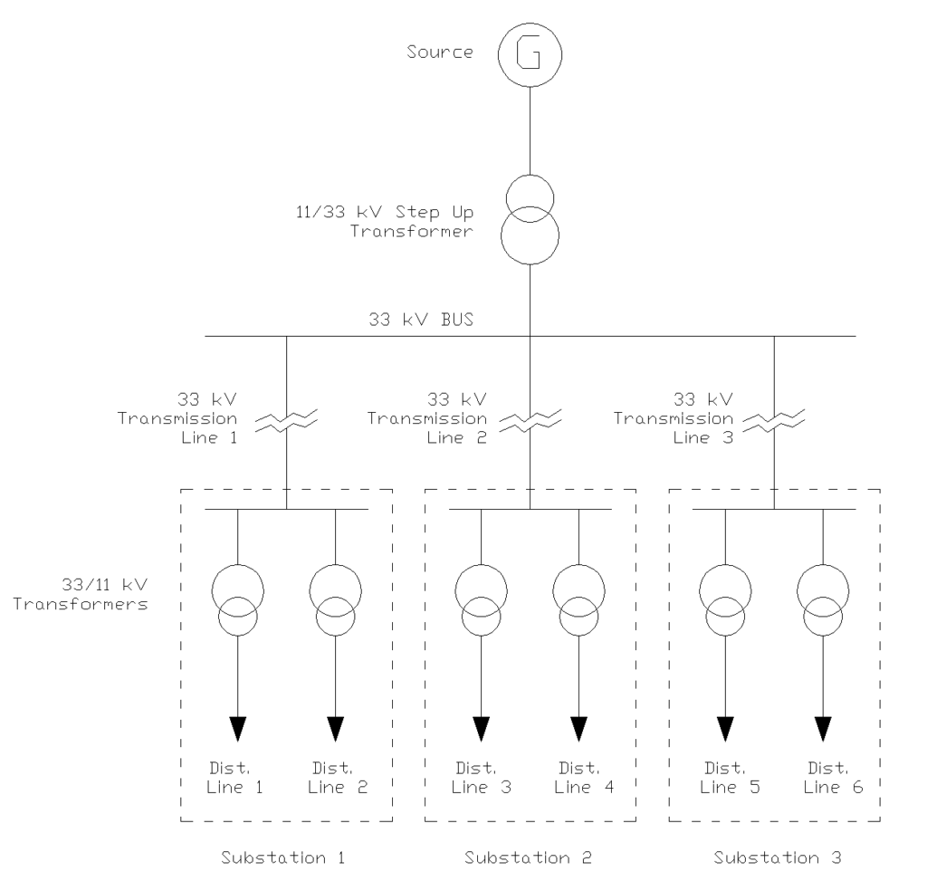
Consider a simple radial distribution feeder supplying power from a substation to various loads. If a short circuit occurs anywhere on this feeder, the current will increase. A non-directional overcurrent relay installed at the substation will detect this overcurrent and, after the preset time delay, it will trip the feeder circuit breaker to isolate the fault. Since power can only flow in one direction in this radial system, there’s no need to check the direction of fault current.
2.3 Applications of Non-Directional Relays
Non-directional relays are predominantly used in radial distribution networks where the source is at one end and loads are distributed along the feeder. In such systems, fault current always flows from the source toward the fault location and the directional discrimination is not necessary.
These relays are also used for transformer protection, motor protection, and generator backup protection. In transformer applications, they protect against overload conditions and through faults. For motors, they provide protection against starting current, running overload, and short circuit conditions.
The simplicity and reliability of non-directional relays make them the first choice when directional sensitivity is not required.
3. Directional Relays
Directional relays are more advanced approach to power system protection. Unlike their non-directional counterparts, these relays consider both the magnitude and direction of current flow when making tripping decisions. They are essential in systems where power can flow in both directions such as interconnected networks, parallel feeders, and ring main systems.
The fundamental difference lies in the relay’s ability to distinguish between faults occurring in different directions. A directional relay will only operate for faults in a specific direction typically the forward direction, and will restrain from operating for faults in the reverse direction. This directional discrimination is achieved by comparing the phase angle between current and voltage at the relay location.
3.1 Key Characteristics of Directional Relays
- Direction-sensitive operation: Responds to faults only in a predetermined direction
- Requires voltage and current inputs: Needs both voltage transformers (VTs, CVTs) and current transformers (CTs)
- Complex but precise: More advanced circuitry for accurate directional determination
- Essential for interconnected systems: Necessary where power flow can be bidirectional
- Better selectivity: Provides improved fault discrimination in complex networks
3.2 Working Principle
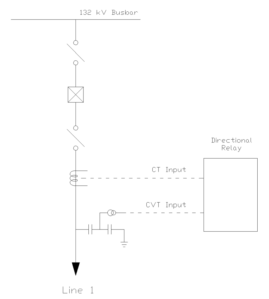
The operation of a directional relay depends on the phase relationship between voltage and current. The relay requires two input quantities: current from a CT and voltage from a VT (or PT – Potential Transformer). The relay measures the phase angle between these two quantities and determines the direction of power flow or fault current.
In a healthy system, current and voltage maintain a certain phase relationship depending on the power factor of the load. During a fault, this phase relationship changes. A directional relay is designed to operate only when the phase angle between voltage and current falls within a specific angular range known as the operating zone or characteristic angle. This zone is typically oriented to detect faults in the forward direction.
Let me illustrate with an example.
Consider two substations A and B connected by a transmission line. If we install a directional overcurrent relay at substation A to protect the line, we want it to trip only for faults occurring on the line between A and B (forward direction). If a fault occurs on a line behind substation A (reverse direction), this relay should not operate, as that fault should be cleared by other relays protecting that section.
3.3 Components and Connections
A directional relay system consists of several components working together. The current transformer provides the current signal proportional to the line current. The voltage transformer supplies the voltage reference signal. Inside the relay, these signals are processed by the directional element, which determines whether the fault is in the forward or reverse direction, and the overcurrent element, which checks if the current magnitude exceeds the threshold.
The voltage reference for directional relays is carefully chosen based on the type of fault being detected. For phase fault detection, phase-to-phase voltages are typically used, while for ground fault detection, phase-to-neutral voltages or residual voltages are employed. The correct selection and connection of these voltage and current inputs are very important for proper directional relay operation.
3.4 Applications of Directional Relays
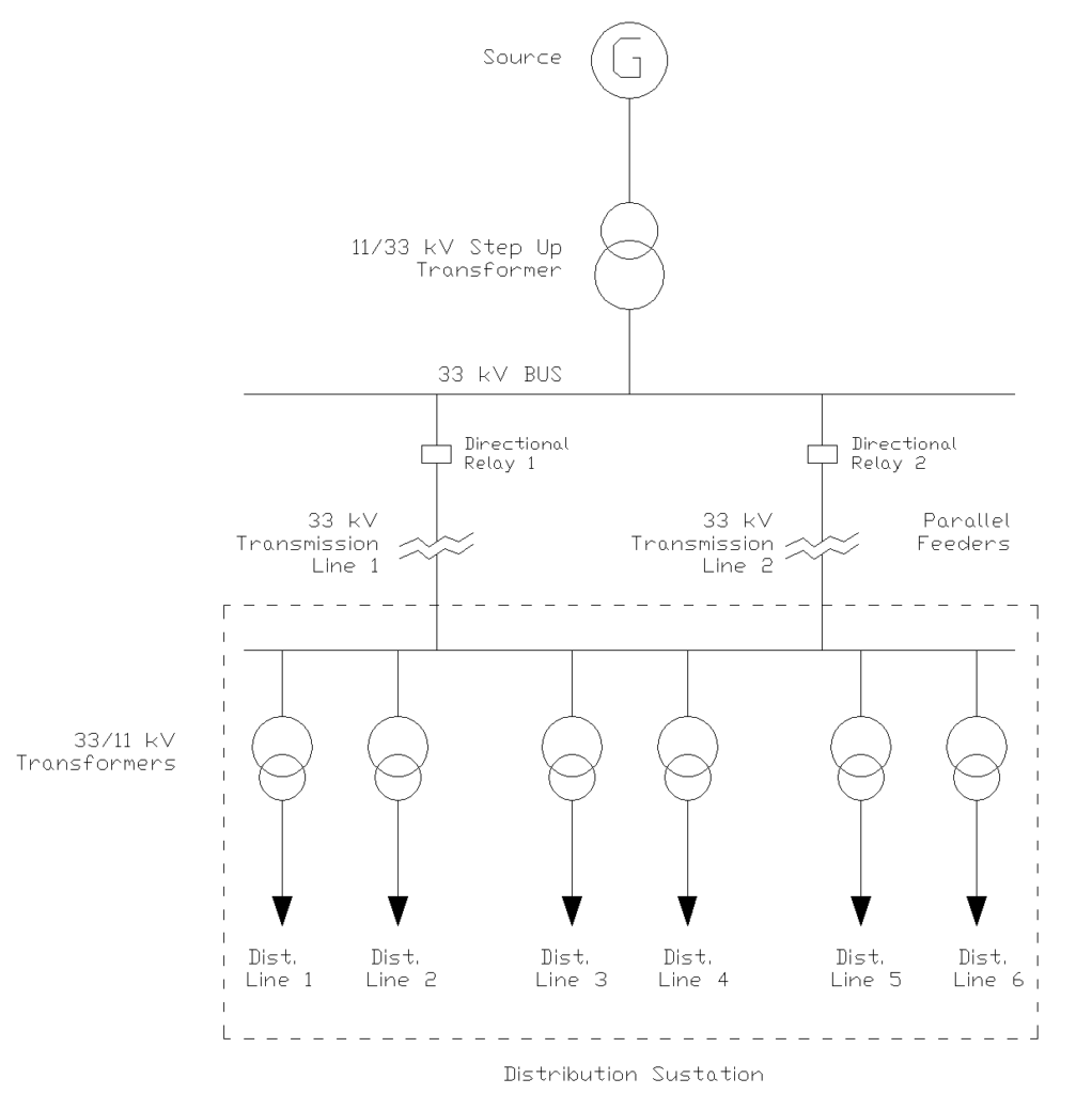
Directional relays are indispensable in parallel feeder arrangements where two or more feeders run between the same substations. In such configurations, a fault on one feeder would be seen by relays on all parallel feeders. Without directional control, all relays would operate, disconnecting healthy feeders unnecessarily. Directional relays make sure that only the relay on the faulted feeder operates.
They are also very much important in ring main systems where multiple sources can feed a fault location. In such systems, fault current can flow from both directions, and directional relays at each end of a line section ensure proper fault isolation. Another important application is in systems with distributed generation, where generators at various locations can contribute to fault currents, making power flow bidirectional.
4. Operating Zone and Characteristic Angle of Directional Relays
4.1 The Concept of Characteristic Angle
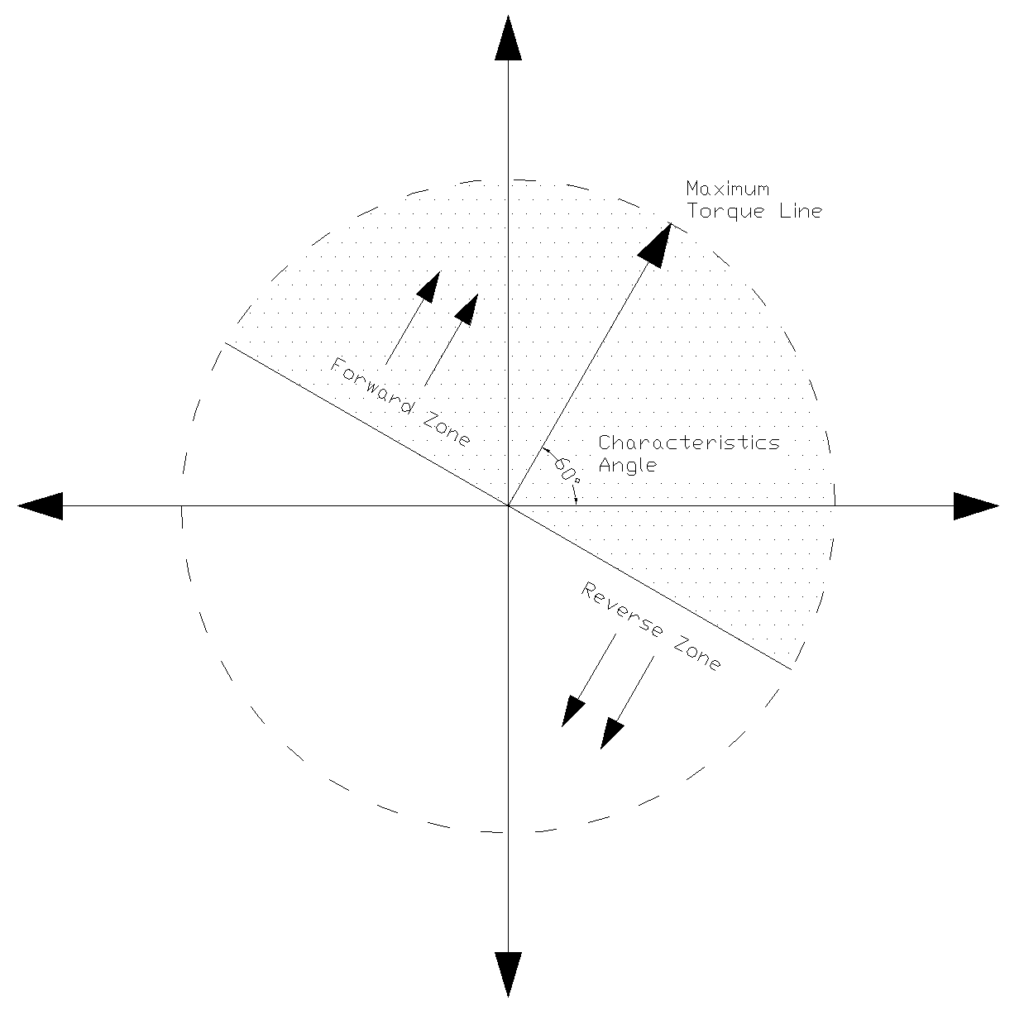
The characteristic angle, also called the Relay Characteristic Angle (RCA) or Maximum Torque Angle (MTA), is the phase angle between voltage and current at which the directional relay produces maximum operating torque.
Think of the characteristic angle as the relay’s “preferred direction” for detecting faults.
When the phase angle between the current and voltage phasors aligns with this characteristic angle, the relay reaches its peak sensitivity. As the actual fault angle deviates from the characteristic angle, the relay’s sensitivity decreases until, at 90 degrees away from the characteristic angle in either direction, the relay reaches its boundary of operation.
The selection of an appropriate characteristic angle depends on the system impedance angle and the type of faults the relay is designed to detect.
For phase fault protection, the characteristic angle ranges from 60° to 75°, while for ground fault protection, angles between 45° and 60° are more common.
4.2 The Torque Equation
The operation of a directional relay is governed by a torque equation that determines whether the relay will operate or restrain. The fundamental equation for relay operating torque is:
\(T = K \times V \times I \times cos(\theta – \alpha)\)
Where:
- T = Operating torque produced by the relay
- K = Relay constant (dependent on relay design and construction)
- V = Voltage magnitude at the relay location (from voltage transformer)
- I = Current magnitude at the relay location (from current transformer)
- θ = Phase angle between the voltage and current phasors
- α = Relay Characteristic Angle (RCA or MTA)
The relay operates (trips the circuit breaker) when the torque T is positive (T > 0), which occurs when:
\(cos(\theta – \alpha) > 0\)
This condition is satisfied when the difference between the actual angle θ and the characteristic angle α falls within ±90 degrees:
\(-90° < (\theta – \alpha) < +90°\)
This ±90° range around the characteristic angle defines the relay’s operating zone. Any fault that produces a current-voltage phase relationship within this zone will cause the relay to operate, while faults outside this zone will be blocked.
4.3 Calculation Example 1: Phase Fault on Transmission Line
Let’s work through an example to illustrate how the characteristic angle and operating zone function in practice.
System Parameters:
- Transmission line impedance: Z = 5 + j20 Ω (per phase)
- Line impedance angle: tan⁻¹(20/5) = 75.96° ≈ 76°
- Relay characteristic angle setting: α = 75° (chosen to match line impedance angle)
- Voltage at relay location during fault: V = 60 kV (phase-to-phase)
- Fault current: I = 2000 A
Scenario: A three-phase fault occurs at the far end of the protected line section.
Step 1: Determine the phase angle between voltage and current
During a fault on an inductive line, the current lags the voltage by approximately the line impedance angle. For our transmission line:
θ = 76° (current lags voltage by 76°)
Step 2: Calculate the angle difference
Angle difference = \(\theta – \alpha = 76° – 75° = 1°\)
Step 3: Evaluate the operating condition
\(cos (\theta – \alpha) = cos(1°) = 0.9998\)
Since cos(1°) > 0 and 1° falls within the range -90° < (θ – α) < +90°, the relay will operate.
Step 4: Calculate relative torque
If we normalize the maximum torque to 1.0 (which occurs when θ = α), the actual torque for this fault is:
Relative torque = \(cos(1°) / cos(0°) = 0.9998 / 1.0 = 99.98%\)
This means the relay operates at nearly maximum sensitivity because the fault angle almost perfectly matches the characteristic angle.
4.4 Calculation Example 2: Ground Fault with Different Characteristic Angle
Ground faults often have different impedance characteristics than phase faults. Let’s examine a ground fault scenario.
System Parameters:
- Zero-sequence line impedance: Z₀ = 15 + j50 Ω
- Zero-sequence impedance angle: tan⁻¹(50/15) = 73.3°
- Ground fault loop impedance angle: Approximately 60°
- Relay characteristic angle for ground fault element: α = 60°
- Residual voltage: V₀ = 20 kV
- Ground fault current: I₀ = 800 A
Scenario: A single-phase-to-ground fault occurs in the forward direction.
Step 1: Determine phase angle
For a ground fault, the residual current lags the residual voltage by approximately the ground fault loop impedance angle:
\(\theta = 60°\)
Step 2: Calculate angle difference
Angle difference \(= \theta – \alpha = 60° – 60° = 0°\)
Step 3: Evaluate operating condition
\(cos(\theta – \alpha) = cos(0°) = 1.0\)
This represents maximum torque operation. The relay operates with 100% of its maximum sensitivity.
4.5 Calculation Example 3: Reverse Fault
Let’s analyze a reverse fault scenario.
System Parameters:
- Same system as Example 1
- Relay characteristic angle: α = 75°
- Fault behind the relay location (reverse direction)
Scenario: A fault occurs on the busbar behind the relay, causing current to flow in the reverse direction.
Step 1: Determine phase angle for reverse fault
For a reverse fault, the current leads the voltage (opposite to forward faults). The phase angle becomes:
\(θ = -104°\) (or equivalently, 256° measured in the positive direction)
Alternatively, we can think of this as 180° – 76° = 104° in the opposite direction, hence -104°.
Step 2: Calculate angle difference
Angle difference \(= \theta – \alpha = -104° – 75° = -179°\)
Step 3: Evaluate operating condition
\(cos(\theta – \alpha) = cos(-179°) = -0.9998\)
Since cos(-179°) < 0 and -179° falls outside the range -90° < (θ – α) < +90°, the relay will NOT operate.
The negative cosine value means the torque is negative (restraining) causing the relay to block.
5. R-X Diagram and Operating Zone
The operating zone of a directional relay can be visualized on an R-X (Resistance-Reactance) diagram, which is commonly used in power system protection analysis. On this diagram:
The horizontal axis represents resistance (R), and the vertical axis represents reactance (X). The relay’s characteristic angle is drawn from the origin at angle α from the R-axis. The operating zone extends ±90° from this characteristic angle line, forming a semicircular region.
Any fault impedance that falls within this semicircular operating zone will cause the relay to operate. Impedance outside this zone are in the restraining region, and the relay will block for such conditions.
6. Selecting the Appropriate Characteristic Angle
Choosing the correct characteristic angle is important for reliable directional relay operation. The selection process involves several considerations:
6.1 For Phase Fault Protection
The characteristic angle should be set close to the protected line’s impedance angle. Transmission lines typically have impedance angles between 70° and 85°, so characteristic angles of 70° to 75° are common.
Distribution lines may have lower impedance angles (60° to 70°) which requires correspondingly lower characteristic angle settings.
For example, if a transmission line has an impedance of Z = 10 + j40 Ω, the impedance angle is:
\(atan(\frac{40}{10}) = 75.96°\)
A characteristic angle setting of 75° would be appropriate.
6.2 For Ground Fault Protection
Ground fault loops include zero-sequence impedances, which typically have different angles than positive-sequence impedances. The characteristic angle for ground fault elements is often set between 45° and 60°.
Consider a system where the ground fault loop impedance angle is calculated as:
Zero-sequence impedance: \(Z_0 = 30 + j50 \text{Ω} \)
Ground fault loop angle: \(atan(\frac{50}{30}) = 59.03°\)
A characteristic angle setting of 60° would be appropriate.
6.3 Practical Considerations
Modern numerical relays offer flexible characteristic angle settings adjustable in 1° or 5° increments from -90° to +90°.
Some relays provide separate characteristic angle settings for different fault types (phase faults, ground faults) and different operating elements (instantaneous, time-delayed).
7. Quadrilateral and Mho Characteristics
While we’ve discussed the basic directional characteristic with a ±90° operating zone, modern relays often employ more advanced characteristics:
7.1 Mho Characteristic:
Distance relays with directional capability often use a Mho characteristic which is inherently directional. The Mho characteristic appears as a circle passing through the origin on the R-X diagram with its diameter determined by the reach setting and characteristic angle.
7.2 Quadrilateral Characteristic:
Advanced directional relays may use quadrilateral characteristics, which provide independent control of resistive and reactive reach along with directional supervision. This allows more precise coverage of fault impedances while maintaining directional discrimination.
8. Testing and Verification of Characteristic Angle
Verifying the correct characteristic angle setting requires specialized test equipment capable of generating voltage and current signals with controlled phase relationships. The testing procedure typically involves:
8.1 Maximum Torque Angle Test
Inject voltage at 0° and current at various angles (typically from -180° to +180° in 15° increments). Record the angle at which the relay operates with minimum current input.
This is the maximum torque angle and should match the characteristic angle setting.
8.2 Operating Zone Boundary Test
Set the injected current magnitude to 150% of the pickup setting. Vary the phase angle between voltage and current until the relay just operates. This boundary should occur at (α – 90°) on one side and (α + 90°) on the other side, confirming the ±90° operating zone.
8.3 Directionality Test
Inject faults at angles representing forward conditions (near α) and reverse conditions (near α ± 180°). Verify the relay operates for forward faults and blocks for reverse faults.
9. Practical Setting Guidelines
Based on extensive field experience and industry standards, here are recommended characteristic angle settings:
Transmission Line Protection:
- Phase elements: 70° to 85° (match line impedance angle)
- Ground elements: 45° to 75° (match ground fault loop impedance)
Distribution Feeder Protection:
- Phase elements: 60° to 75° (distribution lines often have lower X/R ratios)
- Ground elements: 45° to 60° (consider resistive ground fault paths)
Industrial Systems:
- Phase elements: 45° to 70° (cables have lower X/R ratios than overhead lines)
- Ground elements: 30° to 60° (resistive grounding systems common)
Always verify settings through fault studies and field testing to ensure optimal performance for your specific system configuration.
10. Comparing Directional and Non-Directional Relays
10.1 Comparison Table
| Feature | Non-Directional Relay | Directional Relay |
|---|---|---|
| Input Requirements | Current only (from CT) | Current (CT) and Voltage (VT) |
| Complexity | Simple design and operation | More complex with directional element |
| Cost | Lower cost | Higher cost due to additional components |
| Applications | Radial distribution systems | Interconnected systems, parallel feeders |
| Fault Detection | Magnitude-based only | Magnitude and direction-based |
| Coordination | Simpler but limited | More flexible and selective |
| Maintenance | Easier with fewer connections | Requires careful testing of both elements |
10.2 When to Use Each Type
Use non-directional relays when you have a radial system with a single source and unidirectional power flow. They are perfect for simple distribution feeders, single-ended transformer protection, and motor protection applications.
Opt for directional relays in interconnected systems, parallel feeder arrangements, ring main configurations, and any system with distributed generation or multiple sources.
11. Conclusion
Directional and non-directional relays serve as fundamental protective devices in electrical power systems. Each suited to specific applications based on system configuration and protection requirements.
Non-directional relays offer simple, cost-effective protection for radial systems where power flows unidirectionally, while directional relays provide advanced protection capable of discriminating fault direction in complex, interconnected networks.