An Air Circuit Breaker is one of the most widely used protective devices in electrical power systems. This type of circuit breaker uses air at atmospheric pressure to extinguish the electric arc that forms when the contacts separate. Air Circuit Breakers are commonly installed in low voltage and medium voltage electrical systems. They play a major role in protecting electrical equipment from damage caused by overcurrent and short circuit conditions.
In industrial and commercial buildings, Air Circuit Breakers serve as the primary switching and protection device. They are designed to handle large amounts of electrical current. The popularity of Air Circuit Breakers comes from their reliability and ease of maintenance. Engineers and electricians prefer these breakers because they can be serviced without special equipment or gases.
1. What is an Air Circuit Breaker?
An Air Circuit Breaker is an electrical switching device that operates in atmospheric air. It is designed to make and break electrical circuits under both normal and abnormal conditions. When a fault occurs in the electrical system, the Air Circuit Breaker opens its contacts to interrupt the flow of current. The arc that forms during this process is extinguished using air as the interrupting medium.
Air Circuit Breakers are available in different current ratings. They can handle currents ranging from 800 Amperes to 6300 Amperes or even higher. These breakers are mainly used in applications where the voltage level is below 1000 Volts AC. Some models are also designed for DC applications.
For example, consider a large manufacturing plant with multiple production lines. Each production line draws heavy current from the main power supply. An Air Circuit Breaker installed at the main distribution panel protects the entire facility. If a short circuit occurs on any production line, the breaker trips and isolates the faulty section from the rest of the system.
2. Working Principle of Air Circuit Breaker
The working principle of an Air Circuit Breaker is based on arc interruption using air. When the breaker receives a trip signal due to a fault, its operating mechanism separates the main contacts. As the contacts move apart, an electric arc forms between them. This arc must be extinguished quickly to prevent damage to the breaker and the electrical system.
The arc extinction process in an Air Circuit Breaker happens through several methods. The arc is stretched and cooled as it moves through the arc chute. The arc chute contains multiple arc splitter plates made of insulating material. These plates divide the main arc into several smaller arcs. Each smaller arc requires a higher voltage to sustain itself. When the combined voltage requirement exceeds the available system voltage, the arc extinguishes.
The entire arc interruption process takes only a few milliseconds. Modern Air Circuit Breakers can interrupt fault currents within 30 to 60 milliseconds. This fast operation prevents damage to cables and equipment connected to the electrical system.
3. Construction and Components of Air Circuit Breaker
An Air Circuit Breaker consists of several important components that work together to perform switching and protection functions.
3.1 Main Contacts
The main contacts carry the normal load current. They are made of copper alloy material with silver plating to reduce contact resistance. The main contacts are designed for high current carrying capacity. They do not participate in arc interruption.
3.2 Arcing Contacts
The arcing contacts are separate from the main contacts. They are made of arc-resistant materials like tungsten or copper-tungsten alloy. During the opening operation, the main contacts separate first while the arcing contacts continue to carry current. The arc forms on the arcing contacts when they finally separate. This arrangement protects the main contacts from arc damage.
3.3 Arc Chute
The arc chute is a chamber that contains the electric arc during interruption. It consists of multiple arc splitter plates arranged in a stack. These plates are made of materials that can withstand high temperatures. The arc chute guides the arc upward and splits it into smaller sections. This cooling and splitting action helps extinguish the arc quickly.
3.4 Operating Mechanism
The operating mechanism provides the force needed to open and close the breaker contacts. Air Circuit Breakers use different types of operating mechanisms. Manual operation is available using a handle or lever. Electric motor operation allows remote control of the breaker. Spring-charged mechanisms store energy for fast opening and closing operations.
3.5 Trip Unit
The trip unit monitors the current flowing through the breaker. It sends a signal to the operating mechanism when the current exceeds preset limits. Modern Air Circuit Breakers use electronic trip units with adjustable settings. These trip units can detect overcurrent conditions and short circuit faults. They can also provide ground fault protection in some models.
3.6 Frame and Housing
The frame provides mechanical support for all breaker components. It is made of reinforced insulating material or metal with insulating barriers. The housing protects internal components from dust and physical damage. The frame size determines the maximum current rating of the breaker.
4. Types of Air Circuit Breakers
Air Circuit Breakers are classified into different types based on their construction and operating characteristics.
4.1 Plain Break Air Circuit Breaker
The plain break type is the simplest form of Air Circuit Breaker. It has a simple construction with main contacts in an arc chute. The arc is stretched and cooled by the natural movement of hot air. This type is suitable for low current applications. Plain break Air Circuit Breakers are now less common in modern installations.
4.2 Air Blast Circuit Breaker
Air Blast Circuit Breakers use compressed air to blow out the electric arc. The compressed air is stored in a tank and released when the breaker opens. The high-pressure air blast cools the arc and removes ionized particles from the contact gap. This type can interrupt very high fault currents. Air Blast Circuit Breakers are used in medium and high voltage applications.
There are three variations of Air Blast Circuit Breakers:
- Axial Blast Type: The air flows parallel to the arc in the same direction as the contact movement. This design is simple and effective for many applications.
- Cross Blast Type: The air flows perpendicular to the arc. This arrangement provides strong cooling action and fast arc extinction.
- Radial Blast Type: The air flows radially across the arc. This design is used in specific high-voltage applications.
4.3 Magnetic Blow Out Air Circuit Breaker
This type uses magnetic fields to drive the arc into the arc chute. Permanent magnets or electromagnets are positioned near the arcing contacts. When the arc forms, the magnetic field pushes it into the arc chute. This magnetic assistance helps extinguish the arc more quickly. Magnetic blow out breakers are effective for DC applications where the arc does not pass through zero.
4.4 Draw Out Type Air Circuit Breaker
Draw out type Air Circuit Breakers can be removed from their mounting frame without disconnecting cables. The breaker slides on rails and connects to the bus bars through a plug-in arrangement. This design makes maintenance and replacement very convenient. Draw out breakers are commonly used in switchgear panels.
4.5 Fixed Type Air Circuit Breaker
Fixed type Air Circuit Breakers are permanently mounted to the switchboard. The cable connections are made directly to the breaker terminals. This type costs less than draw out versions. However, maintenance requires more time because the breaker cannot be easily removed.
5. Arc Extinction Methods in Air Circuit Breaker
The arc extinction process is the most important function of any circuit breaker. Air Circuit Breakers use several techniques to extinguish the electric arc effectively.
5.1 High Resistance Method
In this method, the resistance of the arc is increased until it can no longer sustain itself. The arc is stretched and cooled as it moves through the arc chute. The resistance increases as the arc length grows. When the arc resistance becomes very high, the current decreases and the arc extinguishes. This method is mainly used in DC circuit breakers.
5.2 Low Resistance or Current Zero Method
This method is used for AC circuit breakers. The arc current passes through zero twice in each cycle of the AC waveform. At the current zero point, the arc momentarily extinguishes. The arc chute removes ionized gases and cools the contact gap during this zero period. If the gap cannot support re-ignition, the arc remains extinguished. Modern Air Circuit Breakers achieve arc extinction within one or two current zero crossings.
5.3 Arc Splitting
Arc splitter plates divide the main arc into multiple smaller arcs in series. Each smaller arc has its own cathode and anode voltage drop. The total voltage required to maintain all the small arcs exceeds the available system voltage. This voltage deficit causes the arc to extinguish. A typical arc chute may contain 10 to 20 splitter plates.
6. Trip Characteristics of Air Circuit Breaker
Air Circuit Breakers have adjustable trip characteristics that determine how they respond to different fault conditions.
6.1 Long Time Delay (LTD)
The long time delay function protects against sustained overload conditions. The trip time decreases as the overload current increases. This inverse time characteristic allows temporary overloads to pass without tripping. The pickup current and delay time are adjustable.
For example, an Air Circuit Breaker rated for 2000 Amperes might be set to trip after 60 seconds at 125% overload. At 150% overload, it would trip in about 30 seconds. This graduated response protects equipment while allowing normal starting currents.
6.2 Short Time Delay (STD)
The short time delay function provides protection against short circuit currents. It operates faster than the long time delay but with a brief intentional delay. This delay allows downstream protective devices to clear the fault first. Short time delay settings are adjustable for both pickup current and time delay.
6.3 Instantaneous Trip
The instantaneous function provides immediate tripping for very high fault currents. There is no intentional time delay. The breaker trips within a few milliseconds when the current exceeds the instantaneous pickup setting. This function protects against severe short circuits that could cause immediate damage.
6.4 Ground Fault Protection
Some Air Circuit Breakers include ground fault protection as an additional feature. This function detects current flowing to ground through unintended paths. Ground fault protection is set at lower current levels than short circuit protection. It helps prevent electrical fires and shock hazards.
6.5 Example of Air Circuit Breaker Trip Characteristics
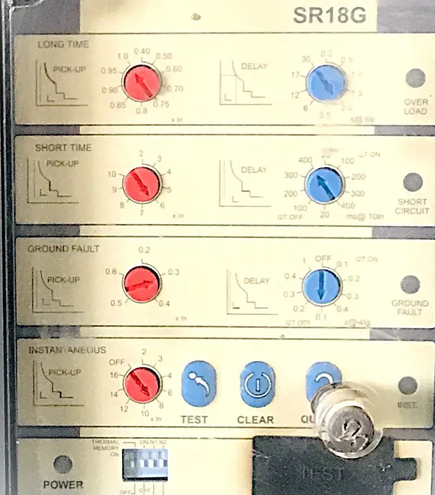
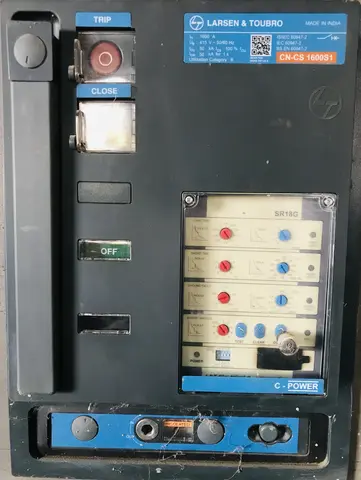
The above image shows the electronic trip unit of the same Air Circuit Breaker. This unit defines how the breaker reacts to overload, short circuit, ground fault and very high fault current. Each row has a red knob for pick‑up current and a blue knob for time delay.
The top row is the long time delay section used for overload protection. The red pick‑up dial is marked from 0.40 to 1.0 times In. For this breaker In is 1600 A, so a setting of 0.9 means the long time function starts to act at 0.9 × 1600 = 1440 A. The blue delay dial sets how long the breaker will carry this overload before tripping. With a higher delay setting, the breaker allows temporary overloads such as motor starting. The small curve beside the dial shows that the trip time decreases as the current goes higher.
The second row is the short time section, used for short circuit currents that are several times the rated current but not yet at the highest level. The red pick‑up dial ranges from 2 to 10 times In. If you set it to 6, the short time function will operate above 6 × 1600 = 9600 A. The blue delay knob is scaled in milliseconds. Lower values give faster tripping, higher values provide coordination with downstream breakers.
The third row is the ground fault section. Here the red pick‑up knob is marked in fractions of In from 0.2 to 0.6. With a 0.3 setting on this 1600 A breaker, the ground fault function starts at about 480 A of residual current. The blue delay knob sets how long the breaker waits before tripping on a ground fault.
The fourth row is the instantaneous section. The red pick‑up dial is marked from about 4 to 16 times In, with an extra “OFF” position. Instantaneous protection has no intentional delay. If it is set to 8, any current above about 8 × 1600 = 12,800 A will cause an immediate trip in a few milliseconds. If the dial is turned to OFF, this function is disabled and only the short time element deals with high fault currents. This setting is useful when you want full selectivity with downstream devices.
At the bottom you can see blue push buttons marked TEST and CLEAR. These allow you to test the trip unit and reset indications without opening the breaker mechanism. The small switch marked THERMAL MEMORY lets you enable or disable the memory feature, which keeps track of recent overloads so that the breaker trips faster if the conductors are still warm.
7. Ratings and Specifications of Air Circuit Breaker
When selecting an Air Circuit Breaker, engineers must consider several ratings and specifications.
7.1 Frame Size
The frame size indicates the physical size of the breaker and its maximum current rating. Common frame sizes include 800A, 1600A, 2500A, 4000A, and 6300A. The frame size must be equal to or greater than the maximum expected current.
7.2 Rated Current
The rated current is the maximum continuous current the breaker can carry without overheating. This rating must match the expected load current with some margin for growth. Breakers can be equipped with trip units rated below the frame size.
7.3 Breaking Capacity
The breaking capacity specifies the maximum fault current the breaker can safely interrupt. This rating is expressed in kilo-amperes at a specific voltage. The breaker must have a breaking capacity greater than the prospective fault current at its installation point.
For example, a breaker installed near a large transformer might face fault currents of 50,000 Amperes or more. The selected breaker must have a breaking capacity of at least 50 kA to safely interrupt such faults.
7.4 Making Capacity
The making capacity is the maximum current the breaker can safely close into. This rating is higher than the breaking capacity because the contacts must withstand the impact forces when closing on a fault. Making capacity is usually 2.2 times the breaking capacity.
7.5 Rated Voltage
The rated voltage specifies the maximum system voltage for the breaker. Common ratings for Air Circuit Breakers include 415V, 480V, 600V, and 690V AC. The system voltage must not exceed the breaker’s rated voltage.
7.6 Operating Duty Cycle
The operating duty cycle specifies how many operations the breaker can perform in a given time. Standard duty cycles include O-t-CO-t-CO where O represents an opening operation and CO represents a close-open sequence. The time t between operations allows the breaker to cool down.
7.7 Example Air Circuit Breaker Nameplate
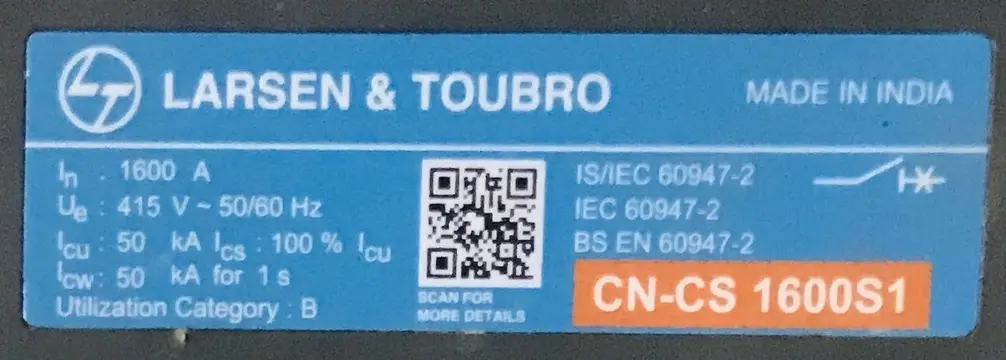
The nameplate in the image belongs to an Air Circuit Breaker from Larsen & Toubro. It summarizes all key electrical ratings in a compact form. When you read such a plate, you can check very quickly whether the breaker suits the system voltage, current and fault level of your installation.
The marking In: 1600 A shows the rated current of the breaker. This means the Air Circuit Breaker can carry 1600 amperes continuously without overheating under normal conditions.
The line Ue: 415 V ~ 50/60 Hz gives the rated operational voltage and frequency. Here the breaker is designed for a three‑phase system with 415 volts at either 50 hertz or 60 hertz. This matches common low voltage distribution systems in many countries, so it can be used in standard industrial and commercial panels.
The values Icu 50 kA and Ics 100% Icu describe the breaking capacity. Icu is the ultimate short‑circuit breaking capacity, so this breaker can interrupt a fault current up to 50 kiloamperes at its rated voltage. Ics is the service breaking capacity, and here it is 100% of Icu. That means the breaker can interrupt 50 kA and still remain fit for further operation within its service limits. For instance, if a fault current of 40 kA occurs on the main bus, this ACB can open the circuit safely and continue in service after inspection.
The marking Icw: 50 kA for 1 s gives the short‑time withstand current. This tells you the breaker and its contacts can carry 50 kA for one second without mechanical or thermal damage when in the closed position. This rating is used when you apply short‑time delays for selectivity so that downstream breakers have time to trip first while the ACB holds the fault current for that brief period.
The line Utilization Category: B refers to the classification in IEC 60947‑2. A category B breaker is designed for applications where short‑time withstand current and delayed tripping are needed, such as main incomers in large distribution boards. It supports time‑graded protection with downstream MCCBs or ACBs. Category B breakers always have an Icw rating, which you can see listed beside it.
On the right side, the standards IS/IEC 60947‑2, IEC 60947‑2, BS EN 60947‑2 show that this Air Circuit Breaker meets international low‑voltage switchgear standards used in many countries.
8. Advantages of Air Circuit Breaker
Air Circuit Breakers offer many benefits that make them popular in electrical installations.
- Simple Construction: Air Circuit Breakers have a straightforward design with fewer components than some other breaker types. This simplicity makes them easier to manufacture and maintain.
- No Special Medium Required: These breakers use atmospheric air for arc extinction. There is no need for oil, vacuum chambers, or SF6 gas. This reduces the cost and complexity of the installation.
- Easy Maintenance: Air Circuit Breakers can be inspected and serviced by trained electricians. The contacts and arc chutes can be examined without special tools. Worn parts can be replaced without replacing the entire breaker.
- Safe Operation: There is no risk of oil fires or toxic gas leaks. Air is a safe and readily available arc extinction medium. This makes Air Circuit Breakers suitable for indoor installations.
- Adjustable Protection Settings: Electronic trip units allow precise adjustment of protection parameters. Settings can be changed to match the specific requirements of the protected circuit.
- Good Short Circuit Performance: Modern Air Circuit Breakers can interrupt fault currents up to 150 kA or more. They provide reliable protection even in systems with high available fault current.
- Long Service Life: With proper maintenance, Air Circuit Breakers can operate for 20 to 30 years. The mechanical parts are designed for thousands of operations.
- Visual Indication: The breaker position can be easily seen from the front panel. Many models include clear ON-OFF indicators and trip flags.
9. Disadvantages of Air Circuit Breaker
Despite their many advantages, Air Circuit Breakers have some limitations.
- Large Physical Size: Air Circuit Breakers are bigger than equivalent vacuum or SF6 breakers. They require more panel space for installation. This can be a problem in facilities with limited space.
- Higher Maintenance Requirements: The arc chute and contacts require regular inspection. Parts may need replacement after a certain number of operations or fault interruptions.
- Not Suitable for High Voltage: Air Circuit Breakers are limited to low and medium voltage applications. For voltages above a few kilovolts, other breaker types are preferred.
- Arc Chute Degradation: The arc splitter plates gradually wear out from repeated arc extinction. The arc chute must be replaced when the plates become damaged.
- Noise During Operation: Air Circuit Breakers produce audible noise when operating. The magnetic blow out and arc extinction process can be quite loud.
- Contact Erosion: The arcing contacts gradually erode with each fault interruption. Regular inspection is needed to check contact condition.
10. Applications of Air Circuit Breaker
Air Circuit Breakers are used in many different electrical installations.
10.1 Industrial Plants
Manufacturing facilities use Air Circuit Breakers to protect motor control centers and power distribution panels. These breakers handle the high currents required by industrial motors and process equipment. The adjustable trip settings allow coordination with downstream protective devices.
10.2 Commercial Buildings
Office buildings, shopping centers, and hospitals use Air Circuit Breakers in their main distribution boards. These breakers protect the building’s electrical infrastructure. They provide reliable switching for building automation and emergency power systems.
10.3 Power Generation
Power plants use Air Circuit Breakers in their auxiliary power systems. These breakers protect generators, transformers, and switchgear from fault currents. They allow safe switching of power circuits during startup and shutdown.
10.4 Marine Applications
Ships and offshore platforms use Air Circuit Breakers in their electrical distribution systems. The salt air environment requires breakers with good corrosion resistance. Marine-rated Air Circuit Breakers meet these special requirements.
10.5 Data Centers
Data centers require highly reliable power distribution. Air Circuit Breakers with electronic trip units provide the precise protection needed. Features like zone selective interlocking improve coordination between breakers.
10.6 Railway Systems
Electric railways use Air Circuit Breakers in their traction power substations. DC-rated Air Circuit Breakers protect the DC traction power supply. The magnetic blow out feature is particularly useful for DC arc interruption.
11. Difference Between Air Circuit Breaker and Other Circuit Breakers
11.1 ACB vs MCB
Miniature Circuit Breakers are smaller devices designed for lower current ratings. MCBs handle currents up to 125 Amperes while ACBs start at 800 Amperes and go higher. MCBs have fixed trip settings while ACBs offer adjustable settings. MCBs are used for final circuits while ACBs protect main distribution systems.
11.2 ACB vs MCCB
Molded Case Circuit Breakers have intermediate ratings between MCBs and ACBs. MCCBs are available from 16 Amperes to 2500 Amperes. MCCBs have a compact molded case while ACBs have an open frame construction. ACBs generally have higher breaking capacities and more adjustable settings than MCCBs.
11.3 ACB vs VCB
Vacuum Circuit Breakers use a vacuum chamber for arc extinction. VCBs are preferred for medium voltage applications from 1 kV to 38 kV. ACBs are mainly used for low voltage applications below 1000 Volts. VCBs require less maintenance but have higher initial costs.
11.4 ACB vs Oil Circuit Breaker
Oil Circuit Breakers use mineral oil for arc extinction and insulation. They are older technology and are being replaced by modern alternatives. ACBs are safer because they do not have flammable oil. Oil circuit breakers are still used in some older installations.
12. Maintenance of Air Circuit Breaker
Regular maintenance keeps Air Circuit Breakers in good working condition.
12.1 Visual Inspection
Regular visual inspection should check for signs of overheating, damage, or contamination. The arc chute should be examined for damage to the splitter plates. The contacts should be checked for excessive erosion or pitting.
12.2 Cleaning
Dust and dirt should be removed from the breaker and its enclosure. The arc chute and insulating surfaces need periodic cleaning. Compressed air can be used to remove loose debris but should not damage components.
12.3 Lubrication
Moving parts require periodic lubrication with the manufacturer’s recommended lubricant. Over-lubrication should be avoided as excess grease can collect dirt. The operating mechanism springs should be inspected for proper tension.
12.4 Contact Maintenance
Main contacts and arcing contacts should be inspected for wear. Contact resistance measurements help evaluate contact condition. Contacts that have worn beyond manufacturer limits should be replaced.
12.5 Trip Unit Testing
Electronic trip units should be tested periodically using primary or secondary injection test equipment. The trip times and pickup currents should be verified against the settings. Faulty trip units should be replaced or repaired.
12.6 Operating Mechanism
The operating mechanism should be exercised regularly to prevent sticking. Manual and electric operations should be tested. Springs should be checked for proper charging and release.
13. Conclusion
Air Circuit Breakers are reliable and widely used protective devices in low voltage electrical systems. Their simple construction, easy maintenance, and adjustable protection settings make them ideal for industrial and commercial applications. By understanding the working principle, types, and proper selection methods, engineers can effectively implement ACBs in power distribution systems.
14. Frequently Asked Questions (FAQs)
An Air Circuit Breaker is an electrical switching device that uses atmospheric air to extinguish the arc formed when its contacts separate. It is used to protect low voltage electrical systems from overcurrent and short circuit faults. Air Circuit Breakers are commonly found in industrial and commercial power distribution systems.
When a fault occurs, the trip unit sends a signal to the operating mechanism. The mechanism separates the main contacts followed by the arcing contacts. An electric arc forms between the separating arcing contacts. The arc is pushed into the arc chute where splitter plates divide it into smaller arcs. These smaller arcs require more voltage than is available and therefore extinguish.
ACB stands for Air Circuit Breaker while MCB stands for Miniature Circuit Breaker. ACBs are designed for high current applications from 800 Amperes and above. MCBs are used for low current applications up to 125 Amperes. ACBs have adjustable protection settings while MCBs have fixed settings. ACBs are used in main distribution panels while MCBs protect individual circuits.
Air Circuit Breakers are used in industrial plants, commercial buildings, power generation facilities, marine vessels, data centers, and railway systems. They protect main distribution panels, motor control centers, and generator circuits. They are installed wherever high current switching and protection is required in low voltage systems.
With proper maintenance, an Air Circuit Breaker can last 20 to 30 years. However, certain components like contacts and arc chutes may need replacement during this time.
Yes, some Air Circuit Breakers are specifically designed for DC applications. These breakers often include magnetic blow out features to help extinguish the DC arc. DC arcs are more difficult to interrupt because there is no natural current zero crossing.