Transformer oil leaks are one of the most common yet dangerous problems faced in electrical power systems. A transformer relies on its insulating oil to perform two major functions — electrical insulation and heat dissipation. Any loss of oil from the transformer tank compromises both of these functions and puts the entire unit at risk of failure. Oil leaks can occur due to aging gaskets, weld defects, corrosion, mechanical damage, or thermal cycling over the years. If left undetected, even a small leak can escalate into a major fault, causing environmental contamination, fire hazards, and expensive downtime.
For utility companies, industrial facilities, and power distribution networks in countries like the United States, Canada, the United Kingdom, Australia, and Germany, transformer oil leak management is a top priority.
In this technical guide, we will discuss everything you need to know about transformer oil leak detection and repair, including its causes, detection methods, repair techniques, preventive maintenance, testing procedures, and environmental compliance requirements. Practical examples are included throughout to help you apply these concepts in real-world scenarios confidently.
1. What Is Transformer Oil and Why Does It Matter?
Transformer oil, also known as insulating oil or mineral oil, is a highly refined petroleum product used inside power transformers and distribution transformers. It serves two primary purposes. First, it acts as an electrical insulator between the windings and the transformer core. Second, it works as a coolant by absorbing and transferring heat away from the windings to the external cooling surfaces.
The oil fills the entire transformer tank and submerges all internal components. This creates a sealed environment that prevents moisture and air from degrading the insulation system. The dielectric strength of transformer oil is measured in kilovolts per centimeter (kV/cm), and fresh mineral oil has a dielectric breakdown voltage of approximately 30 kV or higher as per ASTM D877 testing standards.
If oil leaks out of the transformer, the oil level inside the tank drops. This drop exposes internal components to air, which introduces moisture. Moisture reduces the dielectric strength of the oil and accelerates the aging of cellulose insulation on the windings. A transformer that loses even 5-10% of its oil volume can experience localized overheating and partial discharge activity.
2. Common Causes of Transformer Oil Leaks
Transformer oil leaks do not happen randomly. They are the result of specific mechanical, thermal, or chemical degradation processes that develop over time. Knowing the root causes helps maintenance engineers target their inspections more effectively.
2.1 Gasket Degradation
Gaskets are used at every bolted joint on the transformer — including the main tank cover, bushing flanges, radiator valves, drain valves, and inspection covers. Over time, these gaskets become hard, brittle, and lose their sealing properties.
Nitrile rubber gaskets are commonly used, but they degrade faster when exposed to high temperatures and aggressive oil additives. Cork-neoprene gaskets also shrink and crack after decades of service.
2.2 Weld Joint Failures
The transformer tank is fabricated from steel plates joined together through welding. Imperfections in the original welds, such as porosity, incomplete fusion, or slag inclusions, may not cause leaks immediately.
However, repeated thermal cycling (heating and cooling during load changes) creates stress at these weak points and micro-cracks develop and oil begins to seep through.
2.3 Corrosion
External corrosion is a major concern for transformers installed in coastal areas, industrial zones with chemical exposure, or regions with high humidity. Rust weakens the tank walls and can create pinhole leaks. Internal corrosion, though less common, can occur if the oil contains corrosive sulfur compounds.
2.4 Mechanical Damage
Transformers can suffer physical damage during transportation, installation, or seismic events. Impacts to the tank body, radiator fins, or piping connections can create cracks or loosen fittings. Vibrations from nearby heavy machinery also contribute to fatigue failure at connection points.
2.5 Bushing Seal Failures
High-voltage bushings pass through the transformer tank lid and are sealed with gaskets or O-rings. These seals are subjected to electrical stress, thermal stress, and mechanical vibration simultaneously.
A failed bushing seal not only allows oil to leak out but also permits moisture ingress into the transformer.
2.6 Pressure Relief Device Issues
Transformers are equipped with pressure relief devices (PRDs) that vent excess pressure during internal faults. Sometimes these devices fail to reseat properly after activation, creating a continuous oil leak path.
2.7 Radiator and Cooling System Leaks
External radiators, oil pumps, and cooling fans are connected to the transformer through pipes and flanged joints. Each connection point is a leak source. Radiator fins made of thin steel are especially vulnerable to corrosion-induced pinhole leaks.
3. How to Detect Transformer Oil Leaks
Early detection of oil leaks saves money, prevents environmental damage, and avoids transformer failures. Multiple detection methods exist, ranging from simple visual inspections to advanced online monitoring technologies.
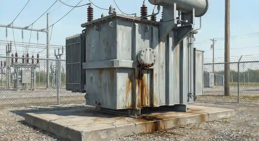
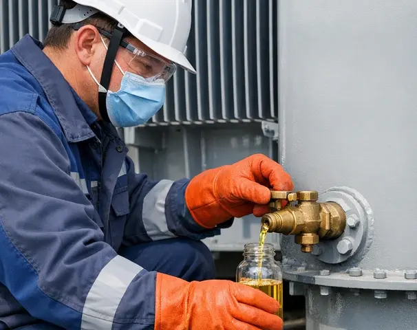
3.1 Visual Inspection
The most basic and widely practiced method is visual inspection. Maintenance personnel walk around the transformer and look for oil stains, wet patches, or drip marks on the tank surface, radiator panels, bushing terminals, valve bodies, and the concrete pad beneath the transformer.
Oil stains often appear as dark streaks running down from the leak point.
Tip: Conduct visual inspections after rainfall. Rainwater washes away dust and makes fresh oil stains more visible against the clean surface.
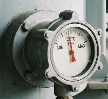
3.2 Oil Level Monitoring
Every transformer is equipped with an oil level gauge (also called a magnetic oil level indicator). This gauge shows the current oil level inside the tank relative to reference marks set at 25°C. A consistently dropping oil level indicates a leak. Modern transformers use electronic oil level sensors that transmit readings to SCADA systems for remote monitoring.
3.3 Dissolved Gas Analysis (DGA)
DGA is a laboratory test performed on oil samples drawn from the transformer. It measures the concentration of gases dissolved in the oil such as hydrogen, methane, ethane, ethylene, acetylene, carbon monoxide, and carbon dioxide. Certain gas patterns indicate overheating, arcing, or partial discharge all of which can result from low oil levels caused by leaks.
ANSI/IEEE C57.104 (IEEE Guide for the Interpretation of Gases Generated in Mineral Oil-Immersed Transformers) provides detailed guidance on interpreting DGA results. The Duval Triangle and Rogers Ratio methods are commonly used for fault diagnosis.
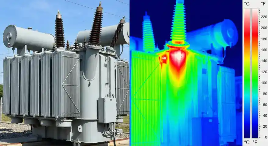
3.4 Infrared Thermography
Infrared (IR) thermal imaging cameras detect surface temperature variations on the transformer tank. An oil leak at a gasket or weld joint often causes a localized temperature anomaly because the escaping oil wets the surface and creates an evaporative cooling effect. Conversely, a low oil level inside the tank causes hot spots at locations where windings are no longer submerged in oil.
Infrared surveys should be conducted under loaded conditions for accurate thermal analysis. NFPA 70B (Standard for Electrical Equipment Maintenance) recommends periodic thermographic inspections for transformers.
3.5 Ultrasonic Leak Detection
Ultrasonic detectors pick up high-frequency sound waves generated by oil or gas escaping through small openings under pressure. These devices are handheld and can pinpoint the exact location of a leak, even in noisy substation environments. The frequency range used is typically 20 kHz to 100 kHz, which is above the range of human hearing.
This method works best for pressurized transformers with nitrogen blankets or sealed conservator systems.
3.6 Pressure Decay Testing
In this method, the transformer is pressurized with dry nitrogen gas to a specified pressure (usually 3-5 psi) and then sealed. The pressure is monitored over a period of time, typically 24 hours. A drop in pressure confirms the presence of a leak. The rate of pressure decay gives an indication of the leak severity.
ANSI/IEEE C57.12.00 (IEEE Standard for General Requirements for Liquid-Immersed Distribution, Power, and Regulating Transformers) includes requirements for factory leak testing of transformer tanks.
3.7 Acoustic Emission Testing
Acoustic emission (AE) sensors can be mounted on the transformer tank wall to detect ultrasonic signals generated by oil flowing through a leak path. This method is useful for identifying leaks in hard-to-reach areas or buried piping.
3.8 Dye Penetrant Testing
For suspected weld cracks, dye penetrant testing (DPT) is a reliable non-destructive examination (NDE) method. A colored or fluorescent dye is applied to the surface. The dye seeps into any surface-breaking cracks. After cleaning the excess dye, a developer is applied, which draws the dye out of the crack and makes it visible. This method is governed by ASME Section V and ASTM E165.
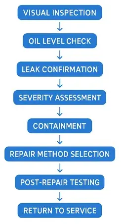
4. Step-by-Step Guide to Repairing Transformer Oil Leaks
Once a leak is detected and its location is confirmed, the next step is to plan and execute the repair. The approach depends on the leak severity, location, and whether the transformer can be taken out of service.
4.1 Step 1: Assess the Leak Severity
Classify the leak into one of three categories:
- Minor Seepage: A thin film of oil is visible, but no dripping occurs. The oil level drop is negligible over weeks.
- Moderate Leak: Oil drips are visible and the oil level drops measurably over days. Immediate planning for repair is needed.
- Major Leak: Oil is flowing or pooling on the ground. Emergency response is required, including containment and possible de-energization.
4.2 Step 2: Contain the Spill
Before starting repairs, contain any spilled oil using absorbent pads, booms, or portable containment trays.
EPA regulations under 40 CFR Part 112 (Spill Prevention, Control, and Countermeasure — SPCC Rule) require facilities with oil-filled equipment to have spill prevention and response plans in place. Failure to contain oil spills can result in heavy fines.
4.3 Step 3: Isolate and De-energize (If Required)
Major leaks and leaks near high-voltage bushings require the transformer to be de-energized and isolated from the power system. Follow proper lockout/tagout (LOTO) procedures per OSHA 29 CFR 1910.147 and your company’s switching protocols.
For minor leaks at accessible locations like drain valves or radiator flange gaskets, online repair may be possible without de-energizing the transformer. However, safety risks must be assessed thoroughly.
4.4 Step 4: Drain Oil to Below the Leak Point (If Needed)
If the leak is at a location that requires welding or gasket replacement, the oil level must be lowered to at least 6 inches below the repair area. The drained oil should be stored in clean, sealed containers to prevent contamination.
4.5 Step 5: Repair the Leak
The repair method depends on the type of leak:
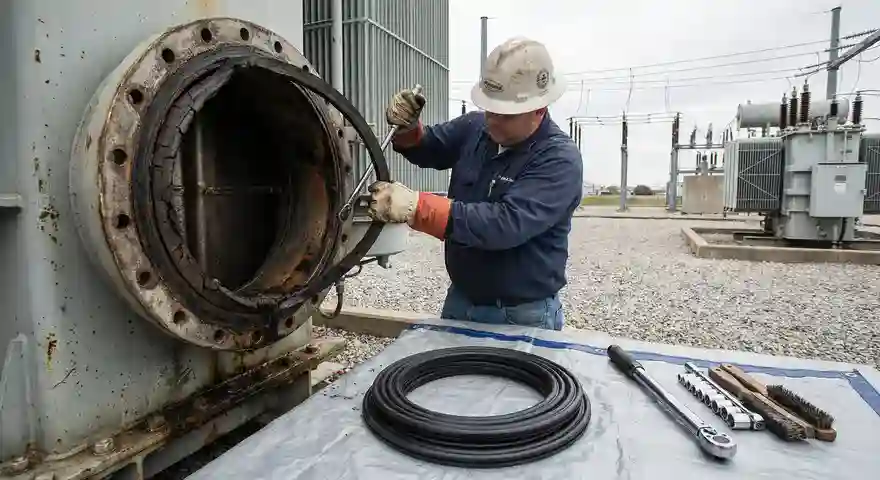
4.5.1 Gasket Replacement
Remove the bolted cover or flange at the leak location. Clean the mating surfaces of old gasket material and any corrosion. Install a new gasket made of oil-resistant material such as nitrile rubber (NBR) or Viton. Torque the bolts to the manufacturer’s specifications in a star pattern to achieve uniform compression.
4.5.2 Weld Repair
For tank wall cracks or weld joint failures, the repair involves grinding out the defective weld, cleaning the area, and re-welding using a qualified welding procedure. The welder must hold certifications per ASME Section IX or AWS D1.1. After welding, the repaired area should be tested using dye penetrant or magnetic particle inspection to verify the integrity of the new weld.
Safety Warning: Never weld on a transformer tank that contains oil or oil vapors. The tank must be thoroughly drained, cleaned, and purged with inert gas (nitrogen) before any hot work is performed. Refer to NFPA 51B (Standard for Fire Prevention During Welding, Cutting, and Other Hot Work).
4.5.3 Epoxy Sealant Application
For minor pinhole leaks or surface porosity in areas where welding is not practical, specially formulated epoxy sealants designed for oil-immersed equipment can be applied as a temporary or semi-permanent fix. The surface must be cleaned and dried before applying the epoxy. This method is often used for online repairs on energized transformers.
4.5.4 Clamp and Band Repairs
Mechanical clamps with rubber gaskets can be applied over leaking pipe joints or small tank punctures. Stainless steel banding with sealant is another option for wrapping around leaking radiator tubes. These are considered temporary repairs and should be replaced with permanent fixes during the next planned outage.
4.5.5 Valve Replacement
Leaking drain valves, sampling valves, or butterfly valves should be replaced entirely rather than repaired. Replacement valves must match the original specifications for pressure rating, material, and connection type.
4.6 Step 6: Refill and Process the Oil
After completing the repair, refill the transformer with oil that meets the specifications of ASTM D3487 (Standard Specification for Mineral Insulating Oil Used in Electrical Apparatus — Type I or Type II). The oil must be tested for dielectric breakdown voltage, moisture content, acidity, and dissolved gas content before filling.
If the transformer was opened to the atmosphere during repair, a vacuum filling process is recommended to remove air and moisture from the insulation system. The vacuum should reach at least 1 mmHg (1 torr) absolute.
4.7 Step 7: Perform Post-Repair Testing
After refilling, the following tests should be performed before re-energizing the transformer:
- Oil Level Verification: Confirm that the oil level is at the correct mark for the ambient temperature.
- Leak Test: Pressurize the tank with nitrogen to 3-5 psi and monitor for 24 hours.
- DGA Baseline: Take an oil sample for dissolved gas analysis to establish a new baseline.
- Insulation Resistance Test: Measure the insulation resistance of windings using a megohmmeter at 500V, 1000V, or 5000V DC depending on the voltage class.
- Power Factor / Dissipation Factor Test: This test measures the dielectric losses in the insulation system and can reveal moisture or contamination.
ANSI/IEEE C57.12.90 (IEEE Standard Test Code for Liquid-Immersed Distribution, Power, and Regulating Transformers) outlines the acceptance criteria for these tests.
5. Preventive Maintenance Strategies to Avoid Oil Leaks
The best approach to dealing with transformer oil leaks is to prevent them from occurring in the first place. A proactive maintenance program can extend the service life of a transformer by decades.
5.1 Scheduled Visual Inspections
Conduct visual inspections of all transformers on a quarterly basis at minimum. Substations with older transformers or units operating in harsh environments should be inspected monthly.
5.2 Oil Sampling and Testing Program
Implement a regular oil sampling program. For power transformers rated 10 MVA and above, DGA samples should be taken annually at minimum. Distribution transformers should be sampled on a risk-based schedule.
5.3 Gasket Replacement Program
Develop a proactive gasket replacement program based on the age and condition of the gaskets. Nitrile rubber gaskets have a typical service life of 15-20 years. Replace all gaskets during major overhauls or retrofits.
5.4 Corrosion Protection
Apply corrosion-resistant coatings to the transformer tank exterior. Zinc-rich primers, epoxy coatings, and polyurethane topcoats provide excellent protection against rust. Reapply coatings every 10-15 years or as needed based on condition assessments.
5.5 Online Monitoring Systems
Invest in online monitoring systems that track oil level, oil temperature, moisture in oil, and dissolved gas content continuously. These systems provide real-time alerts when parameters deviate from normal ranges. The return on investment for such systems is well documented in the power industry.
5.6 Proper Torquing of Bolted Joints
During installation and maintenance, all bolted joints on the transformer should be torqued to the manufacturer’s recommended values. Under-torqued bolts cause gasket leaks. Over-torqued bolts damage gaskets and can distort flanges.
6. Relevant Industry Standards
The following standards are directly applicable to transformer oil leak detection, repair, and maintenance:
| Standard | Title |
|---|---|
| ANSI/IEEE C57.12.00 | General Requirements for Liquid-Immersed Transformers |
| ANSI/IEEE C57.12.90 | Test Code for Liquid-Immersed Transformers |
| ANSI/IEEE C57.104 | Guide for Interpretation of Gases Generated in Oil-Immersed Transformers |
| ANSI/IEEE C57.106 | Guide for Acceptance and Maintenance of Insulating Mineral Oil |
| ANSI/IEEE C57.140 | Guide for Evaluation and Reconditioning of Liquid-Immersed Power Transformers |
| ASTM D3487 | Specification for Mineral Insulating Oil |
| ASTM D877 / D1816 | Dielectric Breakdown Voltage of Insulating Liquids |
| NFPA 70B | Electrical Equipment Maintenance |
| 40 CFR Part 112 | SPCC Rule for Oil Spill Prevention |
7. Environment and Safety
Transformer oil leaks are not just an equipment reliability issue. They also pose serious environmental and safety risks that must be addressed proactively.
7.1 Environmental Impact
Mineral oil is a petroleum product and is classified as a pollutant. Oil that leaks from a transformer can seep into the soil and contaminate groundwater. In the United States, the EPA’s SPCC Rule requires facilities with aggregate aboveground oil storage capacity exceeding 1,320 gallons to maintain an SPCC plan. This plan must include secondary containment provisions, inspection schedules, and spill response procedures.
Older transformers manufactured before 1979 may contain polychlorinated biphenyls (PCBs) in their oil. PCB-contaminated oil leaks require specialized cleanup and disposal procedures governed by 40 CFR Part 761. The cost of PCB remediation can be extraordinarily high.
7.2 Fire Hazard
Mineral transformer oil has a flash point of approximately 145°C (293°F). An oil leak near a high-temperature surface or an electrical arc can ignite and cause a transformer fire. Transformer fires are extremely destructive and can spread to adjacent equipment rapidly. Fire suppression systems, oil containment pits, and fire walls should be part of every substation design.
Natural ester-based transformer fluids (such as Envirotemp FR3) offer a higher flash point (above 300°C) and are biodegradable. These fluids are increasingly used in new transformers and as retrofill options for existing units to reduce fire and environmental risks.
7.3 Personnel Safety
Maintenance workers must follow proper safety procedures when working on transformers with oil leaks. Oil on the ground creates slip hazards. Exposure to oil vapors in confined spaces can cause respiratory issues. Workers must wear appropriate personal protective equipment (PPE), including oil-resistant gloves, safety glasses, and chemical-resistant clothing.
8. Real-World Case Study: Detecting and Repairing a Major Oil Leak
A 138 kV / 69 kV, 60 MVA autotransformer at a transmission substation developed an oil leak in 2019. The leak was first noticed during a routine quarterly inspection when the substation operator observed oil stains on the concrete pad near the transformer’s low-voltage bushing turret.
8.1 Detection Phase
- The oil level gauge showed a 2-inch drop from the normal mark.
- An infrared thermography survey revealed a hot spot near the LV bushing flange.
- DGA results showed elevated levels of hydrogen and carbon monoxide, suggesting low-level overheating.
- Ultrasonic testing confirmed the leak was originating from the LV bushing gasket.
8.2 Repair Phase
- The transformer was de-energized and isolated during a scheduled weekend outage.
- Oil was drained to 12 inches below the LV bushing turret.
- The old cork-neoprene gasket was removed and replaced with a new Viton gasket.
- Bolts were torqued to 45 ft-lbs in a star pattern per the OEM specifications.
- The transformer was vacuum-filled with processed oil meeting ASTM D3487 Type II specifications.
8.3 Post-Repair Verification
- A nitrogen pressure test at 4 psi showed zero pressure decay over 24 hours.
- DGA results taken 30 days after re-energization showed normal gas levels.
- The transformer has been operating leak-free since the repair.
This case illustrates the value of combining multiple detection methods and following a systematic repair process.
9. Conclusion
Transformer oil leaks are a serious maintenance challenge that demands immediate attention and a systematic approach. Early detection through regular visual inspections, oil level monitoring, dissolved gas analysis, infrared thermography, and ultrasonic testing can prevent minor leaks from escalating into major failures. Repair methods range from simple gasket replacements to complex weld repairs depending on the severity and location of the leak.
Investing in online condition monitoring systems offers long-term cost savings and improved reliability for your transformer fleet. Every dollar spent on leak prevention and early detection pays for itself many times over by avoiding unplanned outages, environmental cleanup costs, and premature transformer replacement.
Frequently Asked Questions (FAQs)
Gasket degradation is the most common cause. Gaskets made of nitrile rubber or cork-neoprene harden and crack over time due to thermal aging, losing their ability to maintain a proper seal at bolted flanges.
Yes, minor leaks at accessible locations can sometimes be repaired online using epoxy sealants or mechanical clamps. However, major leaks and leaks near high-voltage components require the transformer to be de-energized for safety.
Power transformers should be visually inspected at least quarterly. Transformers in harsh environments or those over 25 years old should be inspected monthly.
Transformer mineral oil is a petroleum-based pollutant. Oil spills can contaminate soil and groundwater. The EPA’s SPCC Rule (40 CFR Part 112) mandates spill prevention plans for facilities storing oil above threshold quantities.
Viton (fluoroelastomer) gaskets offer superior resistance to high temperatures and chemical degradation compared to nitrile rubber. They are recommended for high-voltage power transformers.
DGA does not directly detect oil leaks, but it can reveal the consequences of low oil levels, such as overheating and partial discharge.
Absolutely not. Welding on a tank containing oil or oil vapors can cause an explosion or fire. The tank must be fully drained, cleaned, and purged with nitrogen gas before any hot work begins.
A pressure decay test involves pressurizing the sealed transformer tank with dry nitrogen gas (typically 3-5 psi) and monitoring the pressure over 24 hours. Any drop in pressure confirms the presence of a leak.