A doorbell is one of the simplest electrical circuits found in residential buildings. The circuit involves a low-voltage transformer, push button, chime unit, and connecting wires. Each component plays a specific role in making the doorbell ring. Getting the wiring right is not difficult once you understand the layout and the function of each part.
Doorbell systems operate on low voltage, usually between 10V and 24V AC. This makes them safer to work with compared to standard 120V or 240V household circuits. However, mistakes in wiring can still lead to a non-functional doorbell, a burnt-out transformer, or even a fire hazard. A proper wiring diagram removes the guesswork and gives you a clear visual reference for installation, troubleshooting, and repair.
In this technical guide, we will discuss everything you need to know about doorbell wiring diagrams, including the circuit components, wiring configurations, transformer selection, multi-button setups, troubleshooting techniques, and relevant electrical codes. Practical examples are included throughout to help you apply these concepts in real-world scenarios confidently.
1. What is a Doorbell Wiring Diagram?
A doorbell wiring diagram is a schematic drawing that shows how the different parts of a doorbell system are electrically connected. It illustrates the path of current from the transformer through the push button and into the chime unit. The diagram uses standard electrical symbols to represent each component.
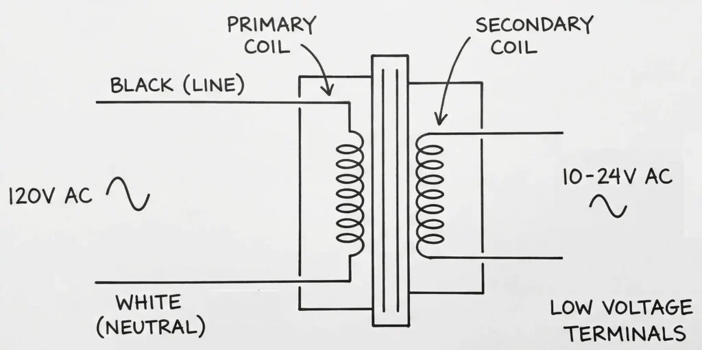
These diagrams follow general conventions used in electrical engineering drawings. The transformer is shown as two coils, the push button as a normally open switch, and the chime as a load. Wires are represented by lines connecting these symbols. Some diagrams also include wire color codes and terminal labels to make installation easier.
A wiring diagram is different from a pictorial diagram. A pictorial diagram shows the physical appearance of the components and their approximate locations. A wiring diagram focuses on the electrical connections and circuit logic. For professional electricians and engineers, the wiring diagram is the preferred reference because it provides a clearer view of the circuit’s operation.
2. Components of a Standard Doorbell Circuit
Before reading any wiring diagram, you need to understand the individual components that make up a doorbell circuit. Here is a breakdown of each part.
2.1 Doorbell Transformer
The transformer steps down the household voltage (120V AC in the US or 240V AC in the UK/Australia) to a lower voltage suitable for the doorbell. Common secondary voltages are 10V, 16V, and 24V AC. The transformer has two sides: the primary side connects to the household power supply, and the secondary side connects to the doorbell circuit.
The transformer is usually mounted on or near the main electrical panel. It may also be located in a utility closet, basement, or attic. The primary side is hardwired to a 120V or 240V circuit and protected by a circuit breaker.
2.2 Push Button (Doorbell Switch)
The push button is a momentary contact switch mounted at the door. It is normally open, meaning the circuit is broken until someone presses the button. Pressing the button closes the circuit and allows current to flow through the chime.
2.3 Chime Unit (Bell or Buzzer)
The chime unit produces the sound. Older systems used electromagnetic bells with a striker and gong. Modern systems use electronic chimes that can produce a variety of tones. The chime unit is typically mounted on an interior wall at a central location in the house.
2.4 Low-Voltage Wiring
The wires used in doorbell circuits are low-voltage thermostat-type wires, usually 18 AWG or 20 AWG. Two-conductor wire (also called bell wire) is used for single-button systems. Three-conductor wire is used for two-button systems (front door and back door).
3. Basic Doorbell Wiring Diagram (Single Button)
The simplest doorbell circuit has one transformer, one push button, and one chime. Here is how the wiring works step by step.
Step 1: The primary side of the transformer connects to a 120V AC power source. One wire goes to the hot (black) wire, and the other goes to the neutral (white) wire. A ground wire connects to the transformer’s grounding screw if available.
Step 2: The secondary side of the transformer has two terminals. One terminal connects to one wire of the push button. The other terminal connects to one terminal of the chime unit (usually labeled “TRANS” on the chime).
Step 3: The second wire from the push button connects to the other terminal of the chime unit (usually labeled “FRONT”).
This creates a simple series circuit. The current path is as follows: Transformer secondary terminal → wire to push button → through the push button (when pressed) → wire to chime “FRONT” terminal → through the chime → wire back to the other transformer secondary terminal.
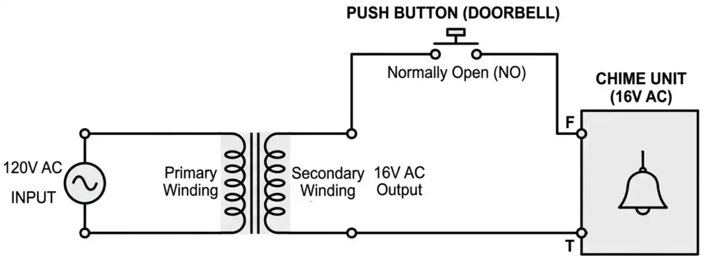
Example: Suppose you have a 16V transformer. One secondary terminal connects via an 18 AWG wire to the front door push button. Another 18 AWG wire runs from the push button to the “FRONT” terminal on the chime. A third wire connects the “TRANS” terminal on the chime back to the other secondary terminal of the transformer. The circuit is complete.
4. Two-Button Doorbell Wiring Diagram (Front and Back Door)
Many homes have two doorbells — one at the front door and one at the back door. The chime unit in these systems has three terminals: “TRANS,” “FRONT,” and “REAR.” The front button produces a “ding-dong” sound, and the rear button produces a single “ding.”
Here is the wiring configuration:
Step 1: Connect one secondary terminal of the transformer to the “TRANS” terminal on the chime unit.
Step 2: Run a wire from the other secondary terminal of the transformer to the front door push button AND to the back door push button. This means both push buttons share a common wire from the transformer. You can splice this wire at a junction point to send one wire to the front and another to the back.
Step 3: Run a wire from the front door push button to the “FRONT” terminal on the chime.
Step 4: Run a wire from the back door push button to the “REAR” terminal on the chime.
The common wire from the transformer feeds both buttons. Each button has its own dedicated return wire to the chime. This allows the chime to distinguish between the front door and back door activations.
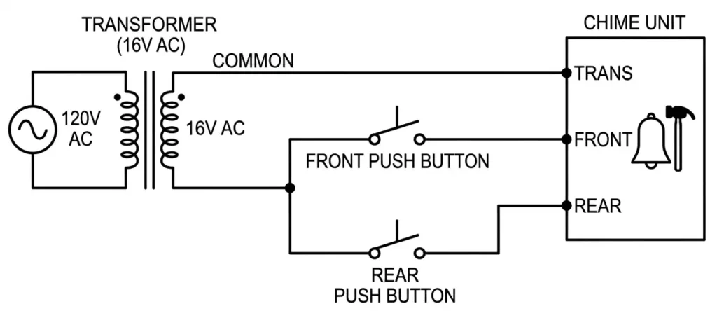
Example: In a two-story home, the transformer is in the basement. A two-conductor wire runs from the transformer’s secondary to a junction box in the hallway. From there, one wire goes to the front door button and another goes to the back door button. Separate wires return from each button to the chime mounted in the hallway. The chime’s “TRANS” terminal connects back to the transformer.
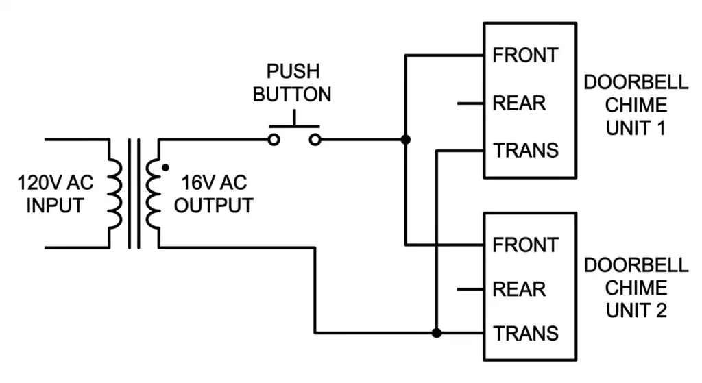
5. Wiring Diagram for Multiple Chimes
Some larger homes or commercial buildings require more than one chime unit. For example, you may want a chime in the living room and another in the bedroom. Multiple chimes can be wired in parallel across the same circuit.
To wire two chimes in parallel:
- Connect the “TRANS” terminal of both chimes to the same transformer secondary terminal.
- Connect the “FRONT” terminal of both chimes to the same wire coming from the front push button.
- If you have a rear button, connect the “REAR” terminal of both chimes to the wire from the rear push button.
Keep in mind that adding more chimes increases the load on the transformer. You may need a transformer with a higher VA (volt-ampere) rating to support multiple chime units. A standard 16V/10VA transformer can usually support one or two chimes. For three or more chimes, consider a 16V/30VA transformer.
6. Smart Doorbell and Video Doorbell Wiring
Smart doorbells and video doorbells like Ring, Nest, and Eufy have become popular in modern homes. These devices replace the traditional push button and connect to your home WiFi network. However, many of them still use the existing doorbell wiring for power.
The wiring for a smart doorbell is similar to a traditional single-button system. The two low-voltage wires from the transformer connect to the two terminals on the smart doorbell unit. There is no polarity concern because the circuit runs on AC.
However, smart doorbells often draw more current than traditional push buttons. They need a continuous power supply to operate the camera, microphone, speaker, and WiFi module. For this reason, most smart doorbell manufacturers recommend a 16V to 24V transformer with at least 30VA capacity.
Some smart doorbells also require a “pro power kit” or “bypass kit” to be installed at the chime unit. This kit prevents the chime from producing a humming noise and allows the smart doorbell to receive steady power even when the button is not pressed.
7. Wireless Doorbell Systems
Wireless doorbells do not require any low-voltage wiring between the push button and the chime. The push button runs on a battery and sends a radio signal to the chime receiver, which plugs into a standard wall outlet.
There is no wiring diagram needed for a wireless doorbell in the traditional sense. However, some hybrid systems combine a wired push button with a wireless chime receiver. In these setups, the push button is wired to the transformer as usual, but instead of a wired chime, the signal is transmitted wirelessly.
If you are replacing a wired doorbell with a wireless one, you can simply disconnect the existing wires and cap them with wire nuts. Make sure to turn off the circuit breaker feeding the doorbell transformer before disconnecting any wiring.
8. Common Doorbell Wiring Mistakes
Several wiring errors can cause a doorbell system to malfunction. Here are the most frequent mistakes.
1. Wrong Transformer Voltage: Using a 24V transformer with a 16V chime can burn out the chime’s solenoid. Always match the transformer voltage to the chime’s rated voltage.
2. Loose Wire Connections: Low-voltage wire connections can become loose over time, especially at screw terminals. A loose connection will cause intermittent operation or complete failure of the doorbell.
3. Incorrect Terminal Assignment: On a two-button system, swapping the “FRONT” and “REAR” wires at the chime will cause the wrong tone to play for each door.
4. Using High-Voltage Wire for Low-Voltage Circuits: Standard 14 AWG or 12 AWG Romex wire is not appropriate for doorbell circuits. Use 18 AWG or 20 AWG low-voltage bell wire instead.
5. No Circuit Breaker on the Primary Side: The transformer’s primary wiring must be connected to a dedicated or shared circuit protected by a breaker. Never hardwire a transformer without circuit protection.
6. Running Low-Voltage and High-Voltage Wires Together: NEC Article 725.136 requires separation between Class 2 (low-voltage) wiring and power wiring. Running them in the same conduit or cable is a code violation.
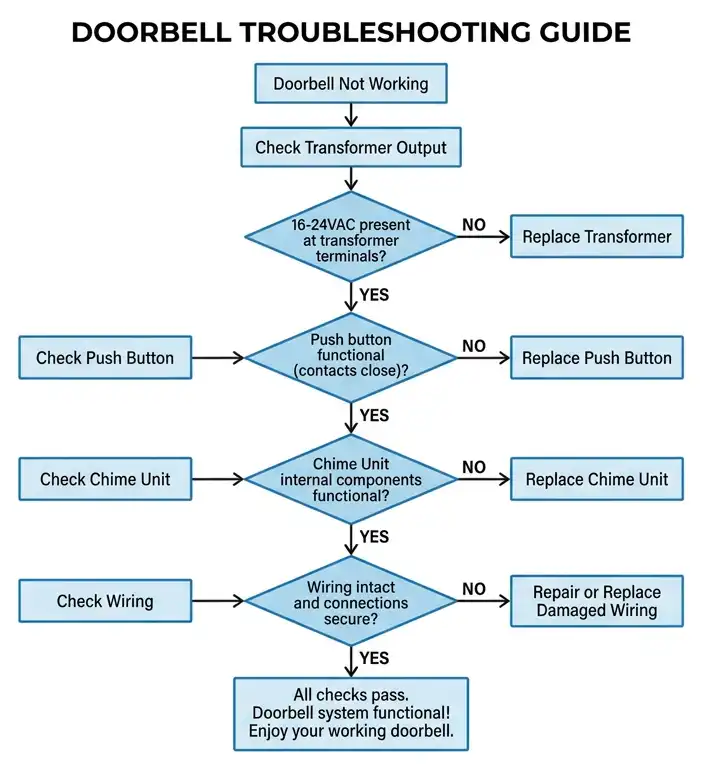
9. How to Troubleshoot a Doorbell Using the Wiring Diagram
A wiring diagram is your best tool for troubleshooting a doorbell that has stopped working. Here is a systematic approach.
Step 1: Check the Transformer Output. Use a multimeter set to AC voltage. Measure the voltage across the secondary terminals of the transformer. You should read a value close to the rated voltage (for example, 16V AC). If you read 0V, the transformer may be defective, or the primary side may have lost power. Check the circuit breaker.
Step 2: Check the Push Button. Remove the push button from the wall and touch the two wires together. If the chime rings, the push button is faulty and needs replacement. If the chime does not ring, the problem is elsewhere in the circuit.
Step 3: Check the Chime Unit. Remove the chime cover and inspect the wiring connections. Make sure all wires are securely attached to the correct terminals. Use your multimeter to check for voltage at the “FRONT” terminal while someone presses the front button. If voltage is present but the chime does not sound, the chime unit is defective.
Step 4: Check the Wiring. If the transformer has output voltage and the push button works, but no voltage appears at the chime, there is a break in the wire. Use a continuity tester to check each wire segment from the transformer to the button and from the button to the chime.
10. Doorbell Wiring Diagram Symbols
Here is a table of common symbols used in doorbell wiring diagrams:
| Component | Symbol Description |
|---|---|
| Transformer | Two parallel coils (primary and secondary) |
| Push Button | A normally open momentary switch |
| Chime/Bell | A circle with a line or a rectangle labeled “CHIME” |
| Wire | A straight line |
| Wire Junction | A dot where two wires connect |
| No Connection | A crossing of two lines without a dot |
| Ground | Three horizontal lines of decreasing length |
These symbols follow standard conventions outlined in ANSI Y32.2 (IEEE 315), which is the American National Standard for graphic symbols used in electrical and electronics diagrams.
11. Transformer Selection and Sizing
Choosing the right transformer is an important part of doorbell installation. The transformer must match the voltage and power requirements of the chime unit. Here are some guidelines.
Voltage Rating: Check the chime manufacturer’s specifications. Most standard chimes operate on 16V AC. Some older chimes use 10V AC, and newer electronic chimes may require 24V AC. Using the wrong voltage can damage the chime or cause it to produce a weak sound.
VA Rating: The VA rating tells you how much power the transformer can deliver. A standard single-chime system needs about 10VA. A two-chime system may need 20VA. If you are also powering a smart doorbell or a video doorbell camera, you may need a 24V/40VA transformer.
12. Practical Example: Full Doorbell Installation Walkthrough
Let us walk through a complete doorbell installation for a new home with one front door button and one chime.
Materials needed:
- 16V/10VA doorbell transformer
- One momentary push button
- One chime unit rated for 16V AC
- 18 AWG two-conductor low-voltage wire
- Wire nuts and electrical tape
- Screwdriver and multimeter
Step 1: Mount the transformer near the electrical panel. Connect the primary side to a 120V circuit. Black wire to hot, white wire to neutral, and green wire to ground. Turn on the breaker and verify 16V AC at the secondary terminals using a multimeter.
Step 2: Run an 18 AWG two-conductor wire from the transformer’s secondary to the front door location. Strip the wire ends and connect one wire to one transformer secondary terminal and the other end to one push button terminal.
Step 3: Run another 18 AWG two-conductor wire from the push button to the chime location. Connect one wire to the other push button terminal and the other end to the “FRONT” terminal on the chime.
Step 4: Run a wire from the “TRANS” terminal on the chime back to the other secondary terminal on the transformer.
Step 5: Press the push button. The chime should produce its tone. If it does not, recheck all connections using the wiring diagram.
This installation follows NEC Article 725 for Class 2 circuits and uses a UL-listed transformer.
13. Safety Precautions for Doorbell Wiring
Even though doorbell circuits operate on low voltage, safety precautions are still necessary.
- Turn off the circuit breaker before working on the transformer’s primary side. The primary side carries 120V or 240V and can cause serious electrical shock.
- Use a voltage tester to confirm that the power is off before touching any wires.
- Do not exceed the transformer’s VA rating. Overloading the transformer can cause overheating and create a fire risk.
- Follow local electrical codes. In the US, doorbell installations must comply with NEC Article 725. In Canada, the Canadian Electrical Code (CEC) applies. In the UK, BS 7671 governs these installations.
- Secure all wire connections with wire nuts or terminal screws. Do not leave exposed wire ends.
- Keep low-voltage wires separated from high-voltage wiring as required by code.
14. Conclusion
A doorbell wiring diagram is a simple but powerful tool for anyone working with residential electrical systems. It shows the exact connections between the transformer, push button, and chime unit. Once you understand the basic single-button circuit, you can easily expand your knowledge to two-button systems, multiple chimes, and smart doorbell installations.
The key takeaway from this guide is that doorbell circuits are low-voltage Class 2 circuits governed by NEC Article 725 (ANSI/NFPA 70). Always match the transformer voltage and VA rating to the chime specifications. Follow local electrical codes and safety practices during installation and troubleshooting. Use a multimeter to verify voltages at each stage of the circuit.
With the wiring diagrams and examples provided in this guide, you should be able to install, modify, or troubleshoot any standard doorbell system with confidence.
15. Frequently Asked Questions (FAQs)
Most standard doorbells use 16V AC. Some older models use 10V AC, and some newer electronic or smart doorbells use 24V AC. Always check the chime manufacturer’s specifications before selecting a transformer.
No. Using a 24V transformer with a 16V chime can damage the chime’s internal solenoid or electronic circuit. Always match the transformer’s output voltage to the chime’s rated voltage.
You need three wires between the chime and the two push buttons. One common wire from the transformer feeds both buttons. Each button has its own return wire to the chime — one to the “FRONT” terminal and one to the “REAR” terminal.
Doorbell circuits typically use 18 AWG or 20 AWG low-voltage wire. This wire is also known as bell wire or thermostat wire.
The transformer is usually mounted near the main electrical panel, in a utility closet, basement, garage, or attic. It is hardwired to a 120V or 240V circuit.
The low-voltage side (secondary side) of a doorbell circuit is safe for most DIY homeowners. However, connecting the transformer’s primary side to a 120V or 240V circuit should be done by a licensed electrician, especially if local codes require a permit.
A humming chime usually indicates that the plunger or striker is stuck or that the voltage is too low. Check the transformer output voltage with a multimeter. Also inspect the chime for dust, debris, or mechanical obstruction.
NEC Article 725 covers Class 2 and Class 3 remote-control, signaling, and power-limited circuits, which includes doorbell circuits.
Yes, you can connect two or more chimes to one transformer as long as the transformer’s VA rating is sufficient to power all the chimes.
Set your multimeter to AC voltage. Place one probe on each secondary terminal of the transformer. The reading should be close to the transformer’s rated output (for example, 16V AC). If the reading is 0V, the transformer is defective or the primary circuit has no power.