If you are studying electrical engineering or working with alternating current (AC) circuits, three terms will come up again and again Peak Value, Average Value, and RMS Value. These three quantities describe different aspects of an AC waveform, and each one serves a specific purpose in circuit analysis and design.
In this technical guide, we will break down each of these values in detail. We will look at their definitions, mathematical formulas, derivations, and real-world applications. By the end of this post, you will have a solid grasp of how these three values relate to each other and why each one matters.
1. Why Do We Need Different Values for AC?
Before we get into the specifics, let’s address a simple question: Why can’t we just use one value to describe an AC signal?
In a DC (direct current) circuit, the voltage or current remains constant. So a single number (say 12V} tells you everything you need to know. But in an AC circuit, the voltage and current change continuously. They rise from zero to a maximum, fall back to zero, reverse direction, reach a negative maximum, and return to zero again. This happens repeatedly in a sinusoidal pattern.
Because of this continuously changing nature, we need different ways to express “how big” or “how strong” the AC signal is. That is exactly where Peak Value, Average Value, and RMS Value come into play.
2. AC Waveform Basics
A standard AC voltage waveform can be expressed mathematically as:
\(v(t) = V_m \times \sin(\omega t)\)
Where:
- \(v(t)\) is the instantaneous voltage at time t
- \(V_m\) is the maximum (peak) value of the voltage
- \(\omega\) is the angular frequency in radians per second
- \(t\) is time in seconds
The same applies to current:
\(i(t) = I_m \times \sin(\omega t)\)
The waveform oscillates between \(+V_m\) and \(−V_m\) (or \(+I_m\) and \(−I_m\) for current). One complete oscillation is called a cycle, and the time taken for one cycle is the period (T). The number of cycles per second is the frequency (f), measured in Hertz (Hz).
With this foundation, let’s now examine each value one by one.
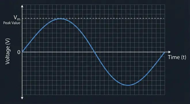
3. What is Peak Value?
The Peak Value (also called the maximum value or amplitude) is the highest value that an AC waveform reaches during one cycle. It is the topmost point on the positive half-cycle or the bottommost point on the negative half-cycle.
For a sinusoidal voltage waveform
\(v(t)=V_{m}\times \sin(\omega t)\), the peak value is \(V_{m}\)
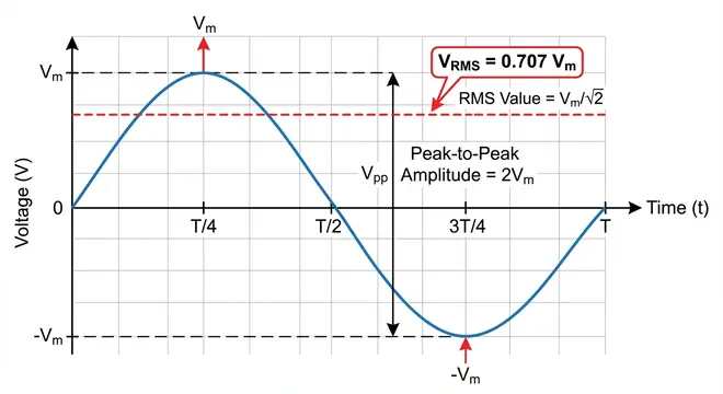
3.1 Peak-to-Peak Value
There is a related term called Peak-to-Peak Value. This is the total distance from the positive peak to the negative peak of the waveform. For a symmetrical sine wave:
\(V_{p-p} = 2 \times V_m\)
So if the peak value is 170V, the peak-to-peak value is 340V.
3.2 Why Peak Value Matters
The peak value tells you the maximum voltage or current that a component in the circuit will experience. This is extremely important when selecting components. For example, if you are choosing a capacitor or a diode for a circuit, you must make sure the component can handle the peak voltage not just the average or RMS value.
If you ignore the peak value and only design for the RMS value, your components could fail because the actual voltage exceeds their rating during each cycle.
3.3 Example
In the United States, the standard household AC supply has an RMS voltage of 120V. The peak value of this supply is:
\(V_m = V_{rms} \times \sqrt{2} = 120 \times 1.414 = 169.7V ≈ 170V\)
So even though we say “120V supply,” the voltage actually swings between +170V and −170V during each cycle.
In the United Kingdom and many other countries, the RMS voltage is 230V. The peak value is:
\(V_m = 230 \times 1.414 = 325.2V ≈ 325V\)
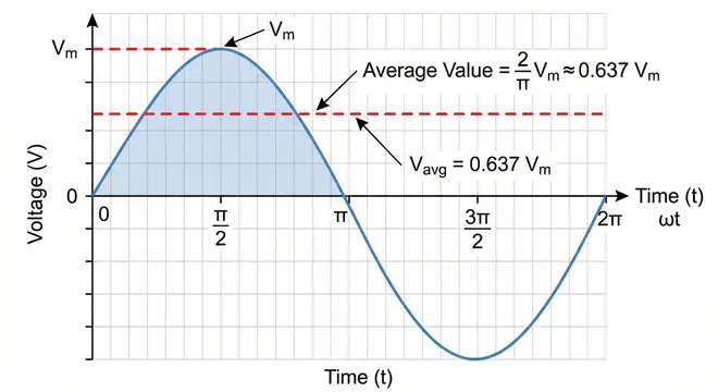
4. What is Average Value?
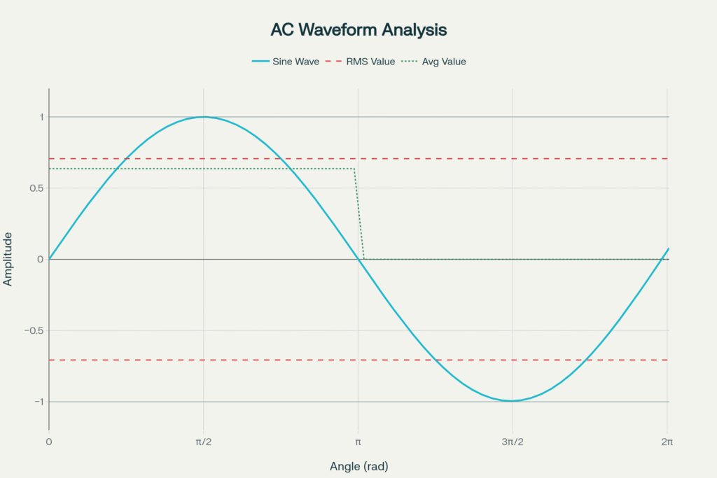
The Average Value of an AC waveform is the arithmetic mean of all instantaneous values over a specific portion of the cycle.
Now here is an important detail. If you calculate the average of a complete sine wave over a full cycle (0 to 2π), the result is zero. This happens because the positive half-cycle and the negative half-cycle are mirror images of each other. They cancel out perfectly.
That is not very useful. So when we talk about the average value of an AC waveform, we usually mean the average over one half-cycle (0 to π).
4.1 Mathematical Formula
For a sinusoidal waveform \(v(t) = V_m \times sin(\omega t)\), the average value over the positive half-cycle is calculated as:
\(V_{avg} = \dfrac{1}{\pi} \int_{0}^{\pi} V_m \sin(\theta) \, d\theta\)
Solving this integral:
\(V_{avg} = \dfrac{V_m}{\pi} \Big[-\cos(\theta)\Big]_{0}^{\pi}\)
\(V_{avg} = \dfrac{V_m}{\pi} \Big[-\cos(\pi) + \cos(0)\Big]\)
\(V_{avg} = \dfrac{V_m}{\pi} \Big[-(-1) + 1\Big]\)
\(V_{avg} = \dfrac{V_m}{\pi} \times 2\)
\(V_{avg} = \dfrac{2V_m}{\pi}\)
\(V_{avg} = 0.637 \times V_m\)
So the average value of a sinusoidal AC waveform is 63.7% of the peak value.
For Current
Similarly, for a sinusoidal current waveform:
\(I_{avg} = \dfrac{2 I_m}{\pi} = 0.637 \times I_m\)
4.2 Where Average Value Is Used
The average value is used in situations involving rectification. When an AC signal passes through a rectifier (such as in a power supply), the output is a pulsating DC signal. The average of this pulsating DC is what matters for many applications.
For a full-wave rectified sine wave, the average value is:
\(V_{avg} = \dfrac{2V_m}{\pi} = 0.637 \times V_m\)
For a half-wave rectified sine wave, the average value is:
\(V_{avg} = \dfrac{V_m}{\pi} = 0.318 \times V_m\)
This is because only one half of the waveform passes through in half-wave rectification.
Average value is also used by permanent magnet moving coil (PMMC) type meters. These instruments respond to the average value of the signal because they work based on the mean torque produced by the current flowing through them.
4.3 Example
If the peak voltage of an AC waveform is 100V, the average value over one half-cycle is:
\(V_{avg} = 0.637 \times 100 = 63.7V\)
5. What is Root Mean Square (RMS) Value?
The RMS Value is the most widely used and most important measure of an AC quantity. The RMS value of an AC voltage or current is defined as:
The equivalent DC value that would produce the same amount of heat (power dissipation) in a resistive load.
This definition is what makes the RMS value so practical. It directly relates the AC quantity to its heating effect, which is the basis of power calculations.
5.1 Why Is It Called Root Mean Square?
The name describes the mathematical process used to calculate it:
- Square all the instantaneous values of the waveform
- Find the Mean (average) of those squared values over one full cycle
- Take the square Root of that mean
Hence: Root → Mean → Square, or RMS.
5.2 Mathematical Derivation
For a sinusoidal waveform \(v(t) = V_m \times \sin(\omega t)\), the RMS value is:
\(V_{rms} = \sqrt{\dfrac{1}{T} \int_{0}^{T} v^2(t) \, dt}\)
For one complete cycle (\(0\) to \(2\pi\)):
\(V_{rms} = \sqrt{\dfrac{1}{2\pi} \int_{0}^{2\pi} V_m^2 \sin^2(\theta) \, d\theta}\)
Using the trigonometric identity: \(\sin^2(\theta) = \dfrac{1 – \cos(2\theta)}{2}\)
\(V_{rms} = \sqrt{\dfrac{V_m^2}{2\pi} \int_{0}^{2\pi} \frac{1 – \cos(2\theta)}{2} \, d\theta}\)
\(V_{rms} = \sqrt{\dfrac{V_m^2}{4\pi} \int_{0}^{2\pi} \Big(1 – \cos(2\theta)\Big) \, d\theta}\)
Now, the integral of \(1\) over \(0\) to \(2\pi\) is \(2\pi\), and the integral of \(\cos(2\theta)\) over \(0\) to \(2\pi\) is \(0\). So:
\(V_{rms} = \sqrt{\dfrac{V_m^2}{4\pi} \times 2\pi}\)
\(V_{rms} = \sqrt{\dfrac{V_m^2}{2}}\)
\(V_{rms} = \dfrac{V_m}{\sqrt{2}}\)
\(V_{rms} = 0.707 \times V_m\)
So the RMS value of a sinusoidal AC waveform is 70.7% of the peak value.
For Current
\(I_{rms} = \dfrac{I_m}{\sqrt{2}} = 0.707 \times I_m\)
5.3 Why RMS Value is So Important
Almost every AC quantity you encounter in daily life is expressed as an RMS value. When someone says “the mains voltage is 120V” or “230V,” they are talking about the RMS value.
Here’s why the RMS value is so dominant:
- Power calculations become straightforward. The power dissipated in a resistor by an AC current is \(P = (I_{rms})^2 \times R\). This is identical in form to the DC power formula \(P = I^2 \times R\). No additional conversion factors are needed.
- AC measuring instruments like multimeters, ammeters, and voltmeters are calibrated to show RMS values. When you measure an AC voltage with a multimeter, the reading is the RMS value.
- Electrical appliance ratings are based on RMS values. A “120V, 60W” light bulb is rated for 120V RMS.
5.4 Example
If the peak voltage of a household AC supply is 170V:
\(V_{rms} = \dfrac{170}{\sqrt{2}} = \dfrac{170}{1.414} = 120.2V ≈ 120V\)
This is exactly the standard household voltage in the United States.
Another example: If a sinusoidal current has a peak value of 10A:
\(I_{rms} = \dfrac{10}{1.414} = 7.07A\)
This means that a 7.07A DC current would produce exactly the same heating effect in a resistor as this 10A peak AC current.
6. Relationship Between Peak, Average, and RMS Values
Let’s summarize the relationships for a pure sinusoidal waveform:
| Quantity | Formula | Numerical Ratio |
|---|---|---|
| Peak Value \((V_m)\) | \(V_m\) | \(1.000\) |
| Average Value \((V_{avg}\)) | \(\dfrac{2V_m}{\pi}\) | \(0.637 \times V_m\) |
| RMS Value \((V_{rms})\) | \(\dfrac{V_m}{\sqrt{2}}\) | \(0.707 \times V_m\) |
From these, we can also derive:
\(V_m = \sqrt{2} \times V_{rms} = 1.414 \times V_{rms}\)
\(V_{avg} = \dfrac{2 \sqrt{2}}{\pi} \times V_{rms} = 0.9 \times V_{rms}\)
\(V_{rms} = \dfrac{\pi}{2\sqrt{2}} \times V_{avg} = 1.11 \times V_{avg}\)
7. Form Factor
The Form Factor is the ratio of the RMS value to the Average value:
\(\text{Form Factor} = \dfrac{V_{rms}}{V_{avg}}\)
For a sinusoidal waveform:
\(\text{Form Factor} = \frac{\dfrac{V_m}{\sqrt{2}}}{\dfrac{2V_m}{\pi}} = \dfrac{\pi}{2\sqrt{2}} = 1.11\)
The form factor tells you about the shape of the waveform. Different waveform shapes have different form factors:
- Sine wave: 1.11
- Square wave: 1.00
- Triangular wave: 1.155
- Sawtooth wave: 1.155
A form factor of 1.0 (square wave) means the RMS and average values are equal. The farther the form factor is from 1.0, the more “peaky” the waveform is.
8. Peak Factor (Crest Factor)
The Peak Factor (or Crest Factor) is the ratio of the Peak value to the RMS value:
\(\text{Peak Factor} = \dfrac{V_m}{V_{rms}}\)
For a sinusoidal waveform:
\(\text{Peak Factor} = \dfrac{V_m}{\dfrac{V_m}{\sqrt{2}}} = \sqrt{2 }= 1.414\)
The peak factor indicates how extreme the peaks of the waveform are compared to its RMS value. This is important when designing circuits that must handle voltage or current spikes.
For different waveforms:
- Sine wave: 1.414
- Square wave: 1.00
- Triangular wave: 1.732
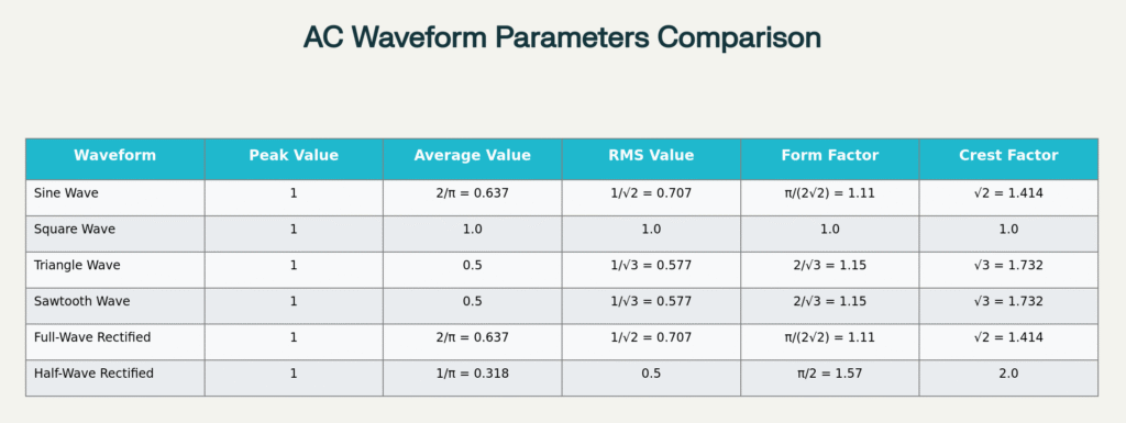
9. Values for Non-Sinusoidal Waveforms
Everything we discussed above applies to pure sinusoidal waveforms. But in real-world applications, you will encounter non-sinusoidal waveforms as well. Let’s briefly look at the peak, average, and RMS values for other common waveforms.
9.1 Square Wave
For a square wave alternating between \(+V_m\) and \(−V_m\):
- Peak Value: \(V_m\)
- Average Value (half-cycle): \(V_m\)
- RMS Value: \(V_m\)
- Form Factor: 1.00
- Peak Factor: 1.00
This makes sense because a square wave maintains a constant magnitude throughout each half-cycle. There is no variation within the half-cycle, so all three values are the same.
9.2 Triangular Wave
For a symmetrical triangular wave with peak value \(V_m\):
- Peak Value: \(V_m\)
- Average Value (half-cycle): \(\dfrac{V_m}{2} = 0.5 \times V_m\)
- RMS Value: \(\dfrac{V_m}{\sqrt{3}} = 0.577 \times V_m\)
- Form Factor: 1.155
- Peak Factor: 1.732
9.3 Sawtooth Wave
For a sawtooth wave with peak value \(V_m\):
- Peak Value: \(V_m\)
- Average Value (half-cycle): \(\dfrac{V_m}{2} = 0.5 \times V_m\)
- RMS Value: \(\dfrac{V_m}{\sqrt{3}} = 0.577 \times V_m\)
- Form Factor: 1.155
- Peak Factor: 1.732
10. Practical Applications and Real-World Examples
10.1 Selecting Components
When you design a circuit, you need to know the peak voltage to select components with appropriate voltage ratings. A capacitor in a rectifier circuit connected to a 230V RMS supply must withstand at least 325V (the peak value). In practice, you would choose a capacitor rated for even higher perhaps 400V to provide a safety margin.
10.2 Power Calculations
When calculating the power consumed by a heater, motor, or any resistive load on AC supply, you use the RMS value.
\(P = \dfrac{V_{rms}^2}{R}\)
For example, a 1000W heater connected to a 120V RMS supply draws:
\(I_{rms} = \dfrac{P}{V_{rms}} = \dfrac{1000}{120} = 8.33A\)
10.3 Rectifier Output
In a full-wave rectifier, the DC output voltage (without filtering) equals the average value:
\(V_{dc} = \dfrac{2V_m}{\pi} = 0.637 \times V_m\)
If the input is 12V RMS from a transformer:
\(V_m = 12 \times 1.414 = 16.97V\)
\(V_{dc} = 0.637 \times 16.97 = 10.81V\)
10.4 Measuring Instruments
Most AC measuring instruments are designed to read RMS values. However, less expensive meters often measure the average value and then multiply by 1.11 (the form factor) to display an equivalent RMS reading. This approach works well for pure sine waves but gives inaccurate results for non-sinusoidal waveforms. True RMS meters, on the other hand, compute the actual RMS value regardless of waveform shape.
10.5 Audio Engineering
In audio systems, the RMS power rating of an amplifier or speaker indicates how much continuous power it can handle. The peak power rating, on the other hand, indicates the maximum instantaneous power during loud transients. A speaker rated at 100W RMS and 200W peak can handle 100W continuously but can survive short bursts up to 200W.
11. Conclusion
Peak Value, Average Value, and RMS Value are three fundamental ways to measure and express AC quantities. The peak value tells you the maximum strength of the waveform. The average value gives the mean over one half-cycle and is useful in rectifier circuits. The RMS value is the most practical of all three because it directly relates to power delivery and heating effects.
12. Frequently Asked Questions (FAQs)
The peak value is the maximum instantaneous value of an AC waveform. The RMS value is the equivalent DC value that produces the same heating effect. For a sine wave, the RMS value is 0.707 times the peak value. The peak value is always higher than the RMS value for any waveform that is not a pure DC signal.
RMS value is used because it directly relates to the power delivered by the AC signal. A 120V RMS AC supply delivers the same power to a resistive load as a 120V DC supply. This makes power calculations simple and consistent. Neither peak value nor average value provides this direct equivalence.
The average value of a pure sine wave over one complete cycle is zero. This is because the positive and negative halves of the wave cancel each other out.
To convert RMS value to peak value for a sine wave, multiply the RMS value by √2 (approximately 1.414).
The form factor of a sine wave is 1.11. It is the ratio of the RMS value to the average value.
The peak factor or crest factor is the ratio of the peak value to the RMS value. For a sine wave, the peak factor is √2 ≈ 1.414.
Most standard AC multimeters measure the average value internally and then multiply by 1.11 to display an equivalent RMS reading. This works accurately for sine waves but can give errors for non-sinusoidal signals. True RMS multimeters calculate the actual RMS value and work accurately with any waveform shape.
In a rectifier circuit, the output is a pulsating DC waveform. The average value of this waveform gives you the DC voltage available at the output. This is the value that a DC load will effectively “see” and use.
Yes. For a perfect square wave, the RMS value equals the peak value because the instantaneous value remains constant at V_m throughout each half-cycle.
The RMS value of a pure DC signal is simply the DC value itself. Since a DC signal does not vary with time, squaring it, averaging it, and taking the root gives back the original value.