Electrical switchboard wiring connections is the backbone of every residential power distribution system. Electrical wiring can seem intimidating, but understanding the basics of switchboard connections is essential for safety and functionality of home electrical systems. In this blog post, we will discuss a typical residential switchboard wiring configuration, helping you understand how power flows safely through your home.
What is a Switchboard?
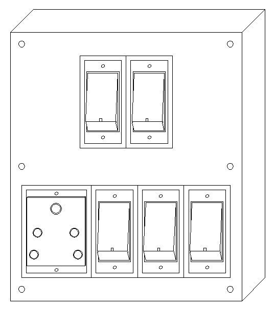
A switchboard is a centralized electrical distribution panel that houses multiple switches and outlets, allowing you to control various electrical fixtures and appliances in your home. The diagram below shows a common 5-switch setup with plug points (5 in 1 switch board connection), designed for residential applications where multiple lights and appliances need individual control.
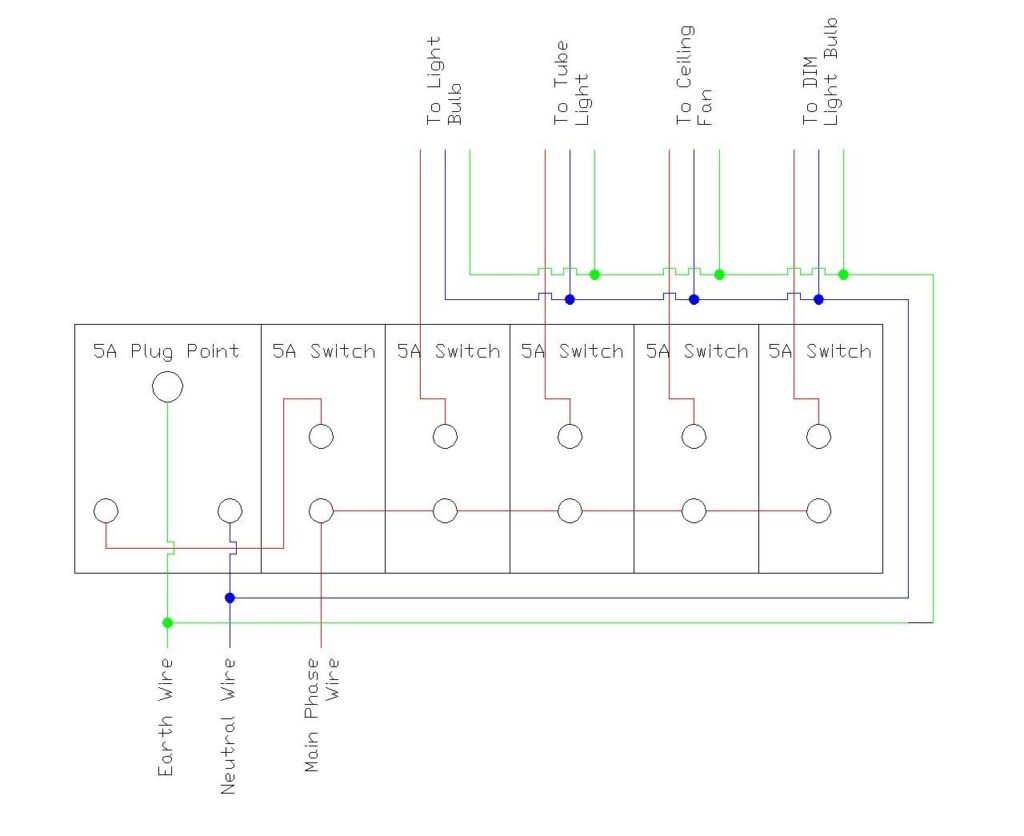
Connection Wiring Diagram (5 Switch and 1 Plug Point)
Key Components of a Switchboard
5A Switches
The switchboard features five 5-ampere (5A) piano switches, which are commonly used in residential applications for controlling lights, tube lights, ceiling fans, and other low-power devices. Each switch operates independently, giving you control over different electrical fixtures throughout your home.
5A Plug Point (Socket Outlet)
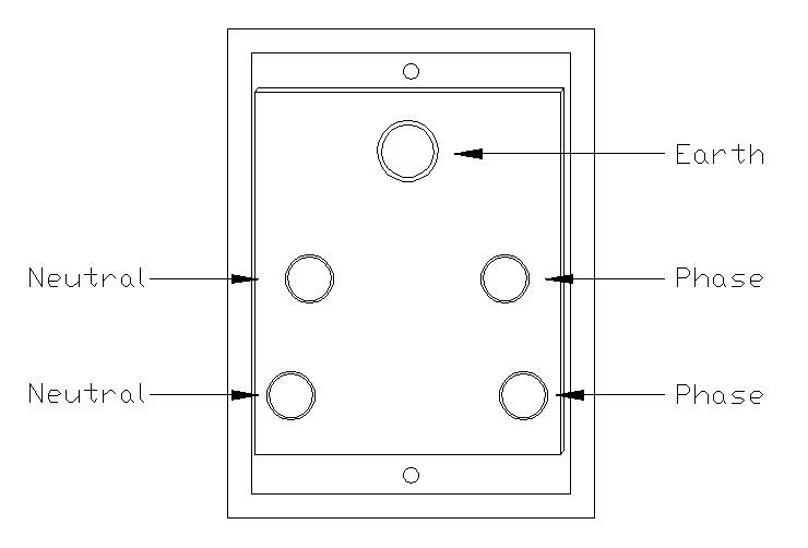
The diagram includes a 5A plug point or socket outlet, which is designed for small appliances and devices. In India, 5A sockets are typically used for devices consuming up to 1,000 watts of power. These are suitable for lamps, mobile chargers, and other low-power appliances.
Connection Terminals
Each switch and socket has specific terminals for connecting wires. The standard markings you’ll find include:
- L (Line/Live): Receives the phase/hot wire
- N (Neutral): Connects to the neutral wire
- E (Earth/Ground): Connects to the protective earth wire
How the Circuit Works
Power Distribution
The electrical supply enters through three main wires: live (phase), neutral, and earth. These connect to the main distribution board, which is protected by a miniature circuit breaker (MCB).
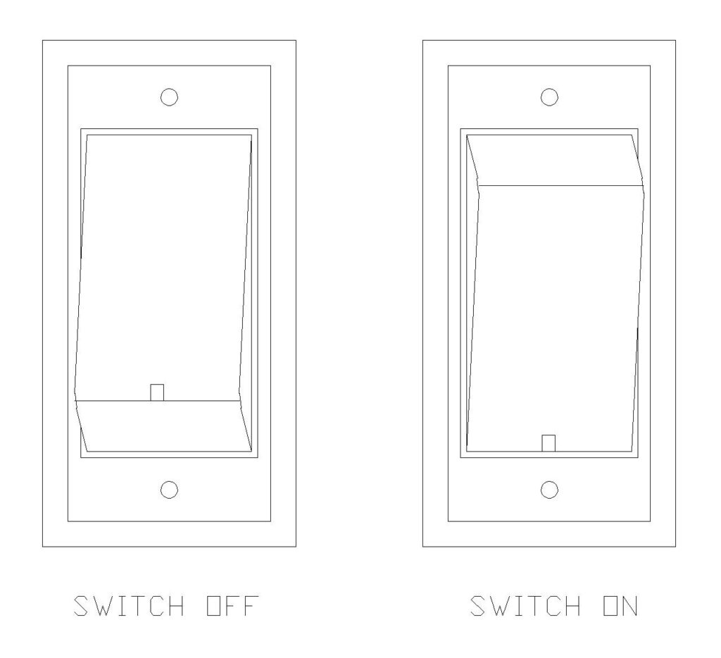
Switch Operation
Looking at the diagram, you’ll notice that the live wire (red line) connects to all five switches in a looped configuration. This is called a “busbar” arrangement, where the phase wire is distributed to multiple switches simultaneously. Each switch has:
- A common terminal at the bottom receiving the phase supply
- An output terminal at the top that connects to the specific light or device
- When you flip the switch, it completes the circuit, allowing current to flow to the fixture
Socket Connection
The 5A plug point connects to the Phase wire through a 5A Switch, and the neutral and earth wires connected directly. The socket will be live (powered) as soon as the switch is flipped so you can plug in appliances at any time. The three-pin design ensures proper grounding for safety.
Load Connections
The diagram shows connections to four different loads:
- Light Bulbs: Connected through switches for on/off control
- Tube Lights: Require a connection through switches
- Ceiling Fan: May require a switch for control
- DIM (Dimmer) Light Bulb: Controlled through a switch with possible dimming capability
Each of these devices receives power through its dedicated switch, with the neutral and earth wires connecting directly to complete the circuit.
The Wire Color Coding
The diagram uses a standard color-coding system that follows Indian electrical standards:
Live/Phase Wire (Brown/Red)
The brown or red wire is the live or phase wire that carries electrical current from the main supply. This wire is always energized when the circuit is on and must be handled with extreme caution. In the diagram, you can see the red line connecting all switches to the main phase supply.
Neutral Wire (Blue/Black)
The blue or black wire serves as the neutral conductor, completing the electrical circuit by providing a return path for current back to the power source. The neutral wire maintains zero voltage relative to ground under normal conditions.
Earth/Ground Wire (Green/Yellow-Green)
The green wire (or green with yellow stripe) is the protective earth or ground wire. This critical safety feature provides a safe path for fault currents to flow into the ground, preventing electric shocks and protecting both equipment and users. The earth wire doesn’t carry current during normal operation but becomes active during electrical faults.
Installation Guidelines
Before starting any electrical work:
- Ensure power is completely isolated at the main distribution board
- Install appropriate PVC or GI conduit from the distribution board to switch board locations
- Use properly rated cables with correct color coding
- Install switch boxes at required positions
Wiring Method
The proper sequence for wiring a switchboard is:
- Connect earth wires first to ensure ground connection is made before any other connection
- Connect neutral wires to their respective terminals
- Finally, connect phase/live wires to switches and outlets
- Test all connections before energizing the circuit
Conclusion
The switchboard wiring is fundamental to electrical safety and home maintenance. The diagram illustrates a well-organized system where multiple switches and outlets work together to provide convenient, safe electrical control throughout your home.
Remember, while knowledge is valuable, always engage qualified electricians for any installation, modification, or repair work. Electricity demands respect, and safety should never be compromised for convenience or cost savings.