Short circuit level, also known as available fault current or fault level, is a fundamental parameter in electrical system design and protection. Short circuit level is the maximum current that could flow at a specific point in an electrical system if a fault condition (short circuit) were to occur. If you don’t know the short circuit level, you cannot safely select a circuit breaker.
In this technical guide we will discuss what short circuit level means, how to calculate it, why it matters, and how to use it in real electrical system design. We’ve also included an interactive Short Circuit Level Calculator at the end of this article that will help your to calculate short circuit level instantly by entering different parameters.
1. What Exactly is Short Circuit Level of a Transformer?
Think of short circuit level as the maximum “surge” of electrical current that would flow through a transformer if its secondary winding terminals were accidentally connected directly together.
In reality, this doesn’t happen intentionally during normal operation, but it represents the maximum possible fault current that the system could experience if something went wrong.
From a technical standpoint, the short circuit level (or fault level) is defined as the maximum symmetrical RMS current available at a particular point in the electrical system during a three-phase bolted fault condition. It’s typically measured in:
- Amperes (A) or kiloamperes (kA) when expressing current magnitude
- Megavolt-amperes (MVA) when expressing fault power capacity
The short circuit level depends on several factors:
- The transformer’s percentage impedance (%Z)
- The transformer’s kVA or MVA rating
- The system voltage at the point of interest
- The upstream source impedance
When we talk about short circuit level, we’re essentially asking: “If something fails in our electrical system and creates an unintended path for current to flow, how much maximum current could flow?” This helps engineers choose circuit breakers, fuses, and other protective devices that are strong enough to safely handle these extreme fault conditions.
2. What is Impedance?
Before you can understand short circuit level, you need to understand impedance. In simple terms, impedance is the transformer’s resistance to the flow of electrical current. Every transformer has built-in impedance due to:
- Winding resistance: The copper windings that make up the transformer naturally resist current flow, similar to how a thicker wire allows more current than a thinner one.
- Leakage reactance: This is the magnetic “leakage” that occurs between the primary and secondary windings, and it also opposes current flow.
The impedance of a transformer is expressed as a percentage on the nameplate (for example, 5%, 6%, or 7.5%). This percentage tells you what fraction of the rated primary voltage is needed to push full-load current through the transformer when its secondary is short-circuited.
Let’s clarify with a simple example: If you have a 500 kVA transformer with a 6% impedance rating on its nameplate, this means you would need to apply 6% of the transformer’s rated primary voltage to make its rated full-load current flow when the secondary winding is shorted. If the primary is rated at 480V, you would need to apply only 28.8 volts (6% of 480V) to create the full-load current under a short circuit condition.
2.1 How Impedance Relates to Short Circuit Current
Here’s the relationship: Lower impedance = Higher short circuit current, and Higher impedance = Lower short circuit current.
\(\text{Short Circuit Current} \propto \frac{1}{\text{Impedance}}\)
This inverse relationship exists because impedance acts like a restrictor in a water pipe. A wider pipe (lower impedance) lets more water flow, while a narrower pipe (higher impedance) restricts the flow.
In your electrical system, a lower-impedance transformer allows more fault current to flow during a fault condition, while a higher-impedance transformer restricts the fault current.
This is why engineers must be very careful when selecting transformers. A transformer with very low impedance might create dangerously high fault currents that could destroy equipment or injure people. On the other hand, a transformer with very high impedance might create voltage drops during normal operation leading to poor voltage regulation for connected loads.
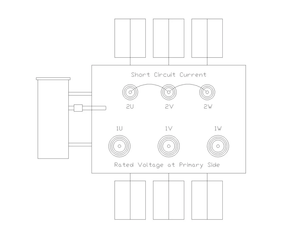
2.2 The Short Circuit Test
To find out the impedance value of a transformer short circuit test is performed during transformer manufacturing. Here’s how this test works:
- The secondary winding of the transformer is physically short-circuited (connected directly together).
- Starting at zero volts, the primary voltage is slowly increased.
- An ammeter measures the current in the primary winding.
- When the ammeter shows the transformer’s rated full-load current, the applied voltage is recorded. This is called the “impedance voltage” (Vsc).
- The percentage impedance is calculated by dividing this impedance voltage by the rated primary voltage and multiplying by 100.
Example calculation:
- A 250 kVA transformer has a rated primary voltage of 11,000V
- During the short circuit test, 495V is applied to the primary before rated current flows
- Percentage Impedance:
\(\text{Impedance ( 25)} = \left( \frac{495V}{11,000V} \right) \times 100 = 4.5\%\)
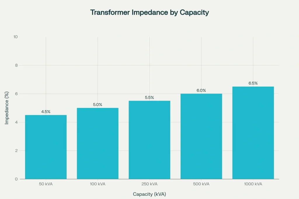
2.3 Typical Impedance Values for Different Transformers
The impedance percentage typically increases slightly with transformer size. Here’s why: Larger transformers need more turns in their windings to reach the required voltages, and more turns create more impedance. The table below shows typical impedance values you’ll encounter in practice:
| Transformer Capacity | Typical Impedance (%) |
|---|---|
| 50 kVA | 4.5% |
| 100 kVA | 5.0% |
| 250 kVA | 5.5% |
| 500 kVA | 6.0% |
| 1000 kVA | 6.5% |
2.4 Reading Impedance from Transformer Nameplate
Every transformer has a nameplate stamped or printed on its side that contains information. To find the impedance:
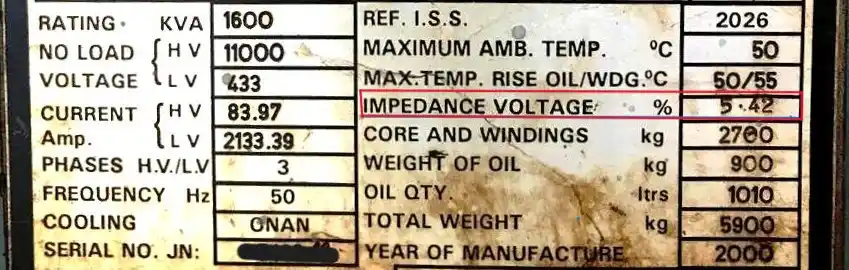
- Locate the transformer nameplate (usually on the side of the transformer, near the bottom)
- Look for a specification that says “Impedance,” “%Z,” or “Impedance Voltage (%)”
- You’ll see a value like “5%”, “6%”, or “7.5%”
This percentage is the impedance value you’ll use in all your fault current calculations. If you can’t find it on the nameplate, check the transformer’s technical specification sheet or datasheet provided by the manufacturer.
3. Calculating Short Circuit Level of a Transformer
Now that you understand impedance, calculating the short circuit level becomes straightforward. Here’s the most commonly used formula for three-phase transformers:
\(\text{Fault Current (A)} = \frac{\text{kVA} \times 1000}{\sqrt{3} \times \text{Voltage (V)} \times \frac{\text{Impedance %}}{100}}\)
Where:
- \(( \text{kVA} )\) = The transformer’s power rating (e.g., 500 kVA)
- \(( \sqrt{3} )\) = Square root of 3 (approximately 1.732, used for three-phase systems)
- \(( \text{Voltage} )\) = The voltage at which you’re calculating the fault level (usually the secondary voltage)
- \(( \text{Impedance %} )\) = The percentage impedance from the transformer nameplate (e.g., 5%, 6%)
Let’s work through a practical example to make this clear:
3.1 Example 1: Small Commercial Building Transformer
Given:
- Transformer rating: 100 kVA
- Secondary voltage: 480V (three-phase)
- Impedance from nameplate: 5%
Solution:
\(\text{Fault Current} = \frac{100 \times 1000}{1.732 \times 480 \times 0.05}\)
\(\text{Fault Current} = \frac{100,000}{41.57} = 2,406 \text{ Amperes}\)
This means if a fault occurs on the 480V secondary bus of this transformer, up to 2,406 amps could flow. Any circuit breakers installed must be rated to safely interrupt at least this much current.
3.2 Example 2: Larger Industrial Transformer
Given:
- Transformer rating: 500 kVA
- Secondary voltage: 480V (three-phase)
- Impedance: 6%
Solution:
\(\text{Fault Current} = \frac{500 \times 1000}{1.732 \times 480 \times 0.06}\)
\(\text{Fault Current} = \frac{500,000}{49.89} = 10,022 \text{ Amperes}\)
4. How Impedance Affects Short Circuit Current
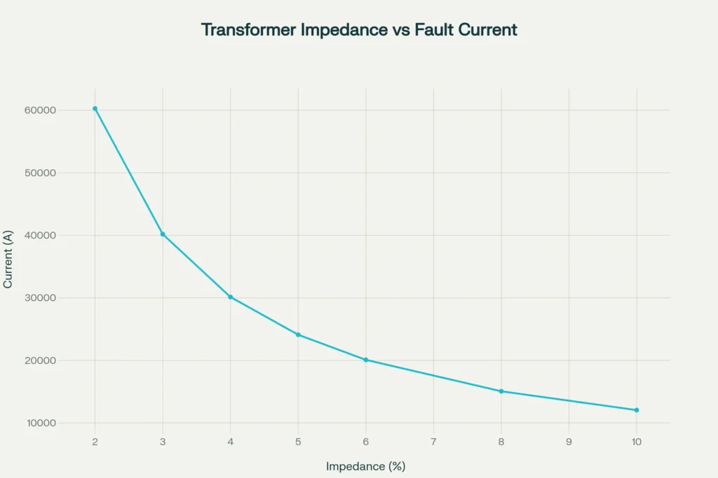
Notice how the short circuit current decreases as impedance increases. A transformer with 2% impedance could produce over 60,000 amps of fault current while the same transformer with 10% impedance would produce only about 12,000 amps. This is why impedance selection is so important in power system design.
5. Why Short Circuit Level Matters: Practical Importance
5.1 Selecting Protective Devices (Circuit Breakers and Fuses)
Every circuit breaker and fuse in your electrical system must have a Short Circuit Current Rating (SCCR) that equals or exceeds the maximum short circuit current at that point in the system.
If you install a circuit breaker with an SCCR of 5 kA in a location where the available fault current is 10 kA, the breaker could fail to interrupt the fault or even explode.
For small transformers rated 10 kVA or less, standard practice assigns an available current of 5 kA on the secondary side so all components must be rated for at least 5 kA. For larger transformers, you must calculate the actual available fault current and specify equipment accordingly.
5.2 Equipment Damage Prevention
When a short circuit occurs the enormous current flow creates mechanical forces on the transformer windings and surrounding equipment. Higher short circuit currents create stronger mechanical forces. In extreme cases, these forces can bend or rupture transformer windings, destroy bus bars, and damage electrical equipment.
Knowing the short circuit level helps you design equipment strong enough to withstand these forces.
5.3 System Voltage Stability
During a fault condition in your electrical system, the available short circuit current determines how much the voltage will sag throughout the system.
A high short circuit level means the system is “strong” and voltages remain relatively stable even during faults. A low short circuit level means the system is “weak,” and voltage sags can be severe.
This matters for sensitive equipment like computers, programmable logic controllers (PLCs), and adjustable frequency drives (AFDs) that require stable voltages to operate properly.
6. The Difference Between High and Low Impedance
| Aspect | Low Impedance (<5%) | High Impedance (>7%) |
|---|---|---|
| Short Circuit Current | Very high, requires expensive, heavy-duty equipment | Lower and more manageable, simpler protection |
| Voltage Regulation | Better – less voltage drop during load changes | Worse – more voltage drop, poorer voltage stability |
| System Stress During Faults | Higher mechanical and thermal stress on equipment | Lower stress, gentler on equipment |
| Cost | Often more expensive components needed | Often cheaper components needed |
| Manufacturing Complexity | More complex design required | Simpler design |
7. How to Use Short Circuit Level in Electrical Design
If you’re designing an electrical system or performing maintenance on an existing one, here’s how to properly use short circuit level information:
Step 1: Identify Your Transformer
Find the transformer serving the circuit or equipment you’re working on. Get its nameplate information including kVA rating, voltages, and impedance percentage.
Step 2: Calculate Available Fault Current
Using the formula from earlier, calculate what the maximum short circuit current would be at that point in your system. Write this value down.
Step 3: Select Protective Equipment
Choose circuit breakers, fuses, switches, and other equipment with Short Circuit Current Ratings (SCCR) that equal or exceed the calculated short circuit current. Never use equipment with an SCCR below the calculated value.
Step 4: Consider System Changes
If you’re adding new transformers in parallel with existing ones, remember that parallel transformers add together their available short circuit levels. A new transformer added in parallel could significantly increase the available fault current, requiring upgrades to your protective equipment.
7.1 Real-World Example: Choosing a Circuit Breaker
Let’s say you’re replacing a distribution panel in a facility. You calculate that the available short circuit current at the panel input is 15 kA. You go to select a main circuit breaker. You find several options:
- Option A: 10 kA SCCR breaker – DO NOT USE – it’s rated below your calculated fault current
- Option B: 14 kA SCCR breaker – DO NOT USE – it’s only barely above your fault level
- Option C: 20 kA SCCR breaker – GOOD CHOICE – it has a comfortable margin above your 15 kA fault current
- Option D: 30 kA SCCR breaker – ACCEPTABLE – it exceeds your needs with extra margin
In practice, choosing Option C or D would be appropriate. The extra margin provides safety headroom if conditions change or if your calculations were slightly conservative.
8. The MVA Method for Calculating Short Circuit Level
Some engineers prefer calculating fault levels using the MVA method instead of calculating amperes directly. In this method:
\(\text{Short Circuit MVA} = \frac{\text{Transformer Rating (MVA)}}{\text{Impedance (per unit)}}\)
Then the short circuit current is calculated from the short circuit MVA. While this method requires an extra calculation step, many engineers find it useful for analyzing systems with multiple transformers and sources.
Example:
A 50 MVA transformer with 7% impedance:
\(\text{Short Circuit MVA} = \frac{50}{0.07} = 714 \text{ MVA}\)
This tells you there’s 714 MVA of available short circuit power at that point in the system.
9. Short Circuit Level Calculator
Formulas Used
- Short Circuit MVA: Ssc = Srated / (Z% / 100)
- Short Circuit Current: Isc = Ssc / (√3 × VLL)
Calculation Results
Short Circuit Level (Fault Level)
–
Short Circuit Current (Isc)
–
Full Load Current (IFL)
–
SC Multiplier (Isc / IFL)
–
Important Note: This calculation assumes infinite bus (no source impedance). For more accurate results, consider the source impedance and cable impedance in the circuit.
Please fill in all fields with valid values.
10. Standards and Regulations
Short circuit calculations must follow established electrical standards to ensure consistency and safety:
- IEC 60909: The international standard for short circuit current calculations
- IEEE Standard C57.12.90: Specifies how transformer impedance should be expressed and measured
- ANSI Standards: American standards for power system protection and equipment ratings
- Local Electrical Codes: Most regions have specific code requirements for short circuit calculations and protective device selection
When designing electrical systems in your area, always check the relevant local electrical code and standards to ensure compliance.
11. Conclusion
Short circuit level is one of the most important – yet often misunderstood – concepts in electrical engineering. By understanding how impedance limits fault current, how to calculate available short circuit levels, and why this matters for equipment selection and system safety, you’re well on your way to designing and maintaining safe, reliable electrical systems.
Remember: every piece of electrical equipment must be rated to safely handle the maximum short circuit current that could reach it. When in doubt about your system’s short circuit levels, consult with a qualified electrical engineer who can perform a detailed study using the appropriate standards for your region and application.