Inductance is a fundamental property of electrical circuits that describes how a coil or conductor responds to changes in current by generating an opposing electromotive force (EMF). This phenomenon plays a crucial role in countless electrical devices—from simple inductors and chokes to complex power transformers and wireless charging systems.
The two primary forms of inductance, self-inductance and mutual inductance, is essential for anyone studying electrical engineering, as these concepts form the foundation for analyzing inductive circuits, electromagnetic coupling, and energy transfer mechanisms.
Self-inductance occurs when a changing current in a single coil induces a voltage within that same coil, always opposing the change that caused it according to Lenz’s Law. Mutual inductance, on the other hand, arises when a changing current in one coil induces a voltage in a neighboring coil through their shared magnetic field.
Both phenomena are governed by Faraday’s Law of Electromagnetic Induction and are measured in the same unit—the henry (H)—named after American physicist Joseph Henry.
This theoretical guide explores the definitions, formulas, practical examples, and real-world applications of both self-inductance and mutual inductance, providing you with the knowledge needed to understand and work with inductive components in electrical systems.
Self-Inductance
Self-inductance is defined as the property of a coil or conductor to oppose any change in the current flowing through it by inducing an EMF within itself. When current flows through a conductor, it creates a magnetic field around it. If this current changes with time, the magnetic field also changes, and according to Faraday’s Law of Electromagnetic Induction, this changing magnetic flux induces an electromotive force in the same conductor. The induced EMF always acts in a direction that opposes the change in current thereby attempting to maintain the “status quo” of the electrical state of the circuit.
The self-inductance of a coil is represented by the symbol \(L\) and is measured in henrys \((H)\).
One henry is defined as the inductance of a coil in which an EMF of one volt is induced when the current through it changes at a rate of one ampere per second.
The SI unit can also be expressed as weber per ampere \((Wb/A)\) or volt-second per ampere \((V·s/A)\).
For most practical applications, smaller units such as millihenry \((mH)\), microhenry \((μH)\), or nanohenry \((nH)\) are commonly used, particularly in radio frequency and audio frequency circuits.
Self-Inductance Formula and Derivation
The fundamental relationship for self-inductance is expressed mathematically as the ratio of the total magnetic flux linkage to the current producing it.
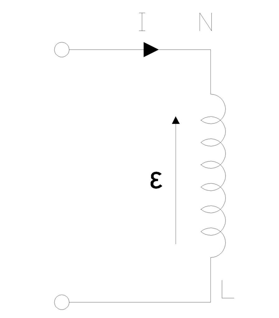
For a coil with \(N\) turns carrying current \(I\), if the magnetic flux through one turn is \(Φ\), then the total flux linkage is \(NΦ\). The self-inductance \(L\) is defined as:
\(L = \frac{N\Phi}{I}\)
From Faraday’s Law, the induced EMF in the coil is given by the negative rate of change of flux linkage:
\(\varepsilon = -N\frac{d\Phi}{dt}\)
Since the flux linkage \(NΦ = LI\), we can write:
\(\varepsilon = -L\frac{dI}{dt}\)
This equation shows that the induced EMF is directly proportional to the rate of change of current, with the proportionality constant being the self-inductance L. The negative sign indicates that the induced EMF opposes the change in current, as stated by Lenz’s Law.
For a long solenoid, which is one of the most common inductive components, the self-inductance can be calculated using the geometry of the coil. A solenoid of length \(l\), cross-sectional area \(A\), with \(N\) turns, and permeability \(μ₀\) (for air core) has a self-inductance given by:
\(L = \frac{\mu_0 N^2 A}{l}\)
This formula demonstrates that self-inductance increases with the square of the number of turns, the cross-sectional area, and the permeability of the core material, while it decreases with the length of the solenoid. If a ferromagnetic core with relative permeability \(μᵣ\) is used, the formula becomes:
\(L = \frac{\mu_0 \mu_r N^2 A}{l}\)
Factors Affecting Self-Inductance
The self-inductance of a coil depends on several physical parameters that engineers can manipulate to achieve desired inductive characteristics.
Number of turns (N) has the most significant impact—since inductance is proportional to \(N²\), doubling the number of turns quadruples the inductance.
The cross-sectional area (A) of the coil also directly affects inductance; larger coils with greater cross-sectional areas produce stronger magnetic fields and higher inductance.
The length of the coil (l) has an inverse relationship with inductance—shorter coils concentrate the magnetic field more effectively, resulting in higher inductance.
The core material plays a crucial role in determining inductance. An air-core inductor has the lowest inductance for a given geometry, while using ferromagnetic materials like iron, ferrite, or laminated steel can increase inductance by a factor of hundreds or thousands due to their high relative permeability. However, ferromagnetic cores introduce non-linearity and losses at high frequencies. The geometry and shape of the coil—whether it’s a solenoid, toroid, or flat spiral—also influences the inductance by affecting how efficiently the magnetic field is concentrated.
Practical Example: Calculating Self-Inductance
Suppose we have an air-core solenoid with 500 turns, a cross-sectional area of 4 × 10⁻⁴ m², and a length of 0.25 m. Using the formula for self-inductance of a solenoid, we can calculate:
Given:
- Number of turns (N) = 500
- Cross-sectional area (A) = 4 × 10⁻⁴ m² = 4 cm²
- Length (l) = 0.25 m = 25 cm
- Permeability of free space (μ₀) = 4π × 10⁻⁷ H/m ≈ 1.26 × 10⁻⁶ H/m
Using the formula: \( L = \frac{\mu_0 N^2 A}{l} \)
\(L = \frac{(1.26 \times 10^{-6}) \times (500)^2 \times (4 \times 10^{-4})}{0.25}\)
\(L = 0.000503 \text{ H} = 0.50 \text{ mH}\)
Mutual Inductance
Mutual inductance is the property of two or more coils by which a change in current in one coil induces an electromotive force in another neighboring coil. This phenomenon occurs because the magnetic field generated by the first coil (primary coil) links with the second coil (secondary coil), and when this field changes, it induces a voltage in the secondary according to Faraday’s Law.
The concept of mutual inductance is fundamental to understanding how transformers, inductive sensors, wireless charging systems, and many other electromagnetic devices operate.
In simple language, when two coils are placed close to each other, some or all of the magnetic flux produced by current in the first coil passes through the second coil. If the current in the first coil changes, the magnetic flux through both coils changes, inducing an EMF in both coils. The EMF induced in the first coil due to its own changing current is self-inductance, while the EMF induced in the second coil due to the changing current in the first coil is mutual inductance.
The magnitude of mutual inductance depends on how effectively the magnetic flux from one coil links with the other, which in turn depends on the geometry of the coils, their relative positioning, the distance between them, and the magnetic properties of the surrounding medium.
Mutual Inductance Formula
The mutual inductance between two coils is quantified by the proportionality constant that relates the induced EMF in one coil to the rate of change of current in the other.
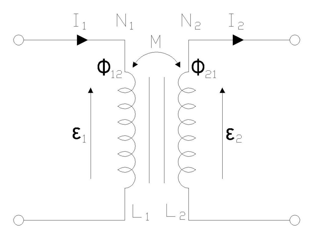
Consider two coils: coil 1 (primary) with \(N₁\) turns and coil 2 (secondary) with \(N₂\) turns. When a current \(I₁\) flows through coil 1, it produces a magnetic field that creates a flux \(Φ₁₂\) through coil 2. The mutual inductance M is defined as:
\(M = \frac{N_2 \Phi_{12}}{I_1}\)
The induced EMF in coil 2 due to the changing current in coil 1 is given by:
\(\varepsilon_2 = -M\frac{dI_1}{dt}\)
Similarly, if we consider the reverse situation where current \(I₂\) flows through coil 2 and induces flux \(Φ₂₁\) in coil 1, we can define another mutual inductance:
\(M = \frac{N_1 \Phi_{21}}{I_2}\)
An important principle in electromagnetic theory known as the reciprocity theorem states that the mutual inductance is symmetric, meaning M₁₂ = M₂₁ = M. This symmetry simplifies the analysis of magnetically coupled circuits, as we need only calculate one value of mutual inductance regardless of which coil is considered primary and which is secondary.
For two coaxial solenoids (one inside the other) with \(N₁\) and \(N₂\) turns, length \(l\), and common cross-sectional area \(A\), the mutual inductance is given by:
\(M = \frac{\mu_0 N_1 N_2 A}{l}\)
This formula shows that mutual inductance is proportional to the product of the number of turns in both coils, the cross-sectional area, and the permeability of the core material, while being inversely proportional to the length.
Coefficient of Coupling
The coefficient of coupling, denoted by \(k\), is a dimensionless parameter that quantifies the degree of magnetic coupling between two inductively coupled coils. It represents the fraction of magnetic flux produced by one coil that links with the other coil. The coefficient of coupling ranges from 0 (no coupling) to 1 (perfect coupling), and it is defined mathematically as:
\(k = \frac{M}{\sqrt{L_1 L_2}}\)
where \(L₁\) and \(L₂\) are the self-inductances of coil 1 and coil 2, respectively, and \(M\) is the mutual inductance between them. Rearranging this equation, we can express the mutual inductance in terms of the self-inductances and coupling coefficient:
\(M = k\sqrt{L_1 L_2}\)
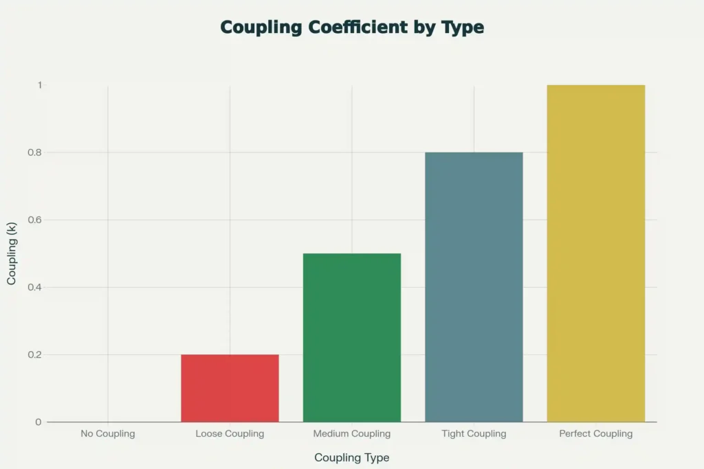
When k = 0, there is no magnetic coupling between the coils—the magnetic flux from one coil does not reach the other at all. This might occur when the coils are very far apart or oriented perpendicular to each other.
When k = 1, perfect coupling exists, meaning all the magnetic flux produced by one coil links completely with the other coil. This ideal scenario is approached in well-designed transformers with closely coupled windings wound on a common ferromagnetic core.
In practical applications, most loosely coupled circuits have k values between 0.01 and 0.3, while tightly coupled transformer windings can achieve k values of 0.95 to 0.99.
The coupling coefficient is critical in transformer design because it directly affects power transfer efficiency between windings. Higher coupling coefficients mean less flux leakage and more efficient energy transfer. Engineers can improve coupling by: using ferromagnetic cores with high permeability, minimizing the distance between windings, ensuring proper winding orientation, and reducing air gaps in the magnetic circuit.
Practical Example: Calculating Mutual Inductance
Let’s work through a practical example to calculate mutual inductance between two coaxial solenoids. Consider solenoid 1 (outer) with 600 turns and solenoid 2 (inner) with 100 turns. The inner solenoid has a radius of 2 cm, and both solenoids have an overlap length of 1 meter.
Given:
- Number of turns in solenoid 1 (N₁) = 600
- Number of turns in solenoid 2 (N₂) = 100
- Radius of inner solenoid (r) = 2 cm = 0.02 m
- Common cross-sectional area (A) = πr² = 3.14 × (0.02)² = 1.256 × 10⁻³ m²
- Overlap length (l) = 1.0 m
- Permeability of free space (μ₀) = 4π × 10⁻⁷ H/m ≈ 1.26 × 10⁻⁶ H/m
Using the formula: \( M = \frac{\mu_0 N_1 N_2 A}{l} \)
\(M = \frac{(1.26 \times 10^{-6}) \times 600 \times 100 \times (1.256 \times 10^{-3})}{1.0}\)
\(M = 9.5 \times 10^{-5} \text{ H} = 0.095 \text{ mH}\)
This calculation shows that the mutual inductance between these two solenoids is approximately 0.095 mH. The relatively small value reflects the limited flux linkage due to the air-core construction.
Comparison: Self-Inductance vs Mutual Inductance
| Parameter | Self-Inductance | Mutual Inductance |
|---|---|---|
| Definition | EMF induced in a coil due to change in its own current | EMF induced in one coil due to change in current in another coil |
| Number of Coils | Single coil | Two or more coils |
| Induced EMF Source | Change in current in the same coil | Change in current in the neighboring coil |
| Magnetic Flux | Self-generated magnetic flux | Linked magnetic flux between coils |
| Formula | L = NΦ/I or L = μ₀N²A/l (solenoid) | M = N₂Φ₁₂/I₁ or M = μ₀N₁N₂A/l (solenoids) |
| Symbol | L (Henry) | M (Henry) |
| Direction of Induced EMF | Opposes the change in current (Lenz’s Law) | Can be in same or opposite direction depending on orientation |
| Energy Transfer | No energy transfer between circuits | Energy transfer between circuits |
| Applications | Inductors, chokes, filters, energy storage | Transformers, coupled inductors, wireless charging |
| Depends On | Number of turns, coil geometry, core material, permeability | Number of turns in both coils, coupling coefficient, distance, orientation |
Applications in Electrical Engineering
Transformers and Power Systems
Transformers represent the most significant practical application of mutual inductance in electrical engineering.
A transformer consists of two or more coils (primary and secondary windings) wound on a common ferromagnetic core, designed to maximize the coupling coefficient between the windings. When an alternating current flows through the primary winding, it creates a time-varying magnetic flux in the core. This changing flux links with the secondary winding, inducing an AC voltage according to Faraday’s Law. The voltage transformation ratio depends on the turns ratio between primary and secondary windings, allowing transformers to step voltage up or down as needed for power transmission and distribution.
Inductors and Chokes
Self-inductance finds extensive application in inductors and chokes, which are passive components designed specifically to utilize inductive properties.
Inductors store energy in magnetic fields and are used in tuned circuits, oscillators, and LC filters. In resonant circuits, inductors combine with capacitors to select specific frequencies, enabling applications in radio receivers, transmitters, and signal processing systems.
Chokes are inductors designed to block or “choke” alternating current while allowing direct current to pass relatively unimpeded. They function by presenting high impedance to AC signals while offering low resistance to DC, making them invaluable for filtering power supplies, preventing radio frequency interference, and isolating different sections of electronic circuits.
In switch-mode power supplies, inductors play a critical role in energy storage and transfer. During the “on” phase of the switching cycle, current builds up in the inductor, storing energy in its magnetic field. During the “off” phase, the collapsing magnetic field releases this stored energy to the load, smoothing out the pulsed input and providing a regulated DC output.
Wireless Power Transfer and Inductive Sensors
Mutual inductance enables wireless power transfer technologies that have gained prominence in consumer electronics and industrial applications.
Inductive charging systems, found in smartphones, electric toothbrushes, and electric vehicles, use loosely coupled coils to transfer power across an air gap without physical electrical connections. The primary coil (transmitter) generates a time-varying magnetic field when energized by high-frequency AC current. This field induces current in the secondary coil (receiver) through mutual inductance, which is then rectified and regulated to charge the device battery. Although the coupling coefficient is relatively low (k ≈ 0.1-0.5) due to the air gap and positioning tolerances, modern systems achieve reasonable efficiency through resonant inductive coupling and sophisticated power electronics.
Inductive proximity sensors utilize mutual inductance to detect metallic objects without physical contact. These sensors contain an oscillating coil that generates a high-frequency magnetic field. When a metal object enters this field, eddy currents are induced in the metal, which in turn create a secondary magnetic field. This secondary field couples back to the sensor coil through mutual inductance, altering the coil’s effective inductance and damping the oscillation. The sensor’s detection circuit monitors these changes to determine the presence, distance, or type of metallic object.
Measuring and Testing Inductance
Measuring Self-Inductance
- LCR meters: Apply an AC signal and measure impedance. Since inductive reactance \((X_L = 2\pi f L)\), the meter computes L directly.
- Bridge methods (e.g., Maxwell’s bridge): Use balanced AC circuits with standard components for precise measurement.
- In transformer testing, open-circuit and short-circuit tests can extract magnetizing and leakage inductance values. Frequency Response Analysis (FRA) detects changes in winding inductance, used for diagnostics.
Testing Mutual Inductance
- Apply a known current to the primary winding, measure the induced voltage in the secondary.
- Calculate using \((M = \varepsilon_2 / (dI_1/dt))\) or, for a sinusoidal input, \((M = V_2 / (2\pi f I_1))\).
- The coupling coefficient k can be found by measuring self-inductances and mutual inductance and applying \((k = M/\sqrt{L_1 L_2})\).
Advanced transformer and coil diagnostics often use polarity tests, turns ratio tests, and frequency response analysis.
Energy Storage in Inductors
The energy stored in an inductor’s magnetic field is:
\(W = \frac{1}{2} L I^2\)
Increasing inductance or current increases stored energy rapidly. In practical design, avoid core saturation and manage I²R and core losses.
Solved Numerical Examples
Example 1: An air-core solenoid has an inductance of 12 mH. The current through the solenoid changes from 2 A to 2.3 A in 0.4 seconds. Calculate the magnitude of the induced EMF.
Solution:
Given data:
- Self-inductance (L) = 12 mH = 0.012 H
- Initial current (I₁) = 2 A
- Final current (I₂) = 2.3 A
- Change in current (ΔI) = I₂ – I₁ = 0.3 A
- Change in time (Δt) = 0.4 s
- Rate of change of current: \( \frac{dI}{dt} = \frac{0.3}{0.4} = 0.75 \text{ A/s} \)
Using the formula for induced EMF due to self-inductance:
\( |\varepsilon| = L\left|\frac{dI}{dt}\right|\)
\( |\varepsilon| = 0.012 \times 0.75 = 0.009 \text{ V} = 9 \text{ mV} \)
Answer: The magnitude of the induced EMF is 9 mV. The negative sign in Faraday’s Law indicates this EMF opposes the increase in current according to Lenz’s Law.
Example 2: Two coils have self-inductances L₁ = 2 H and L₂ = 8 H. The mutual inductance between them is M = 4 H. Calculate the coefficient of coupling.
Solution:
Given data:
- Self-inductance of coil 1 (L₁) = 2.0 H
- Self-inductance of coil 2 (L₂) = 8.0 H
- Mutual inductance (M) = 4.0 H
Using the formula for coefficient of coupling:
\( k = \frac{M}{\sqrt{L_1 L_2}}\)
\( k = \frac{4.0}{\sqrt{2.0 \times 8.0}} = \frac{4.0}{\sqrt{16.0}} = \frac{4.0}{4.0} = 1.0 \)
Answer: The coefficient of coupling k = 1.0, indicating perfect coupling where 100% of the magnetic flux from one coil links with the other coil. This represents an ideal scenario that can be approached in tightly wound transformer coils on a high-permeability core.
Example 3: Two coils have a mutual inductance of 3 mH. If the current in the primary coil changes from 4 A to 16 A in 0.03 seconds, calculate the EMF induced in the secondary coil.
Solution:
Given data:
- Mutual inductance (M) = 3 mH = 0.003 H
- Initial current in primary (I₁) = 4 A
- Final current in primary (I₂) = 16 A
- Change in current (ΔI) = 16 – 4 = 12 A
- Time interval (Δt) = 0.03 s
- Rate of change: \( \frac{dI_1}{dt} = \frac{12}{0.03} = 400 \text{ A/s} \)
Using the formula for induced EMF due to mutual inductance:
\( |\varepsilon_2| = M\left|\frac{dI_1}{dt}\right| \)
\( |\varepsilon_2| = 0.003 \times 400 = 1.2 \text{ V} \)
Answer: The induced EMF in the secondary coil is 1.2 V.
Example 4: A transformer has 500 turns in its primary winding and operates on 230 V AC supply. If the mutual inductance between primary and secondary is maximum (k = 1), how many turns should the secondary have to produce 12 V output?
Solution:
Given data:
- Primary turns (N₁) = 500
- Primary voltage (V₁) = 230 V
- Secondary voltage (V₂) = 12 V
- Perfect coupling (k = 1)
For an ideal transformer with perfect coupling, the voltage ratio equals the turns ratio:
\( \frac{V_2}{V_1} = \frac{N_2}{N_1} \)
\( N_2 = N_1 \times \frac{V_2}{V_1} = 500 \times \frac{12}{230} = 26.09 \text{ turns} \)
Answer: The secondary should have approximately 26 turns to produce 12 V output.
Example 5: An inductor with self-inductance of 50 mH carries a current of 4 A. Calculate the energy stored in its magnetic field.
Solution:
Given data:
- Self-inductance (L) = 50 mH = 0.05 H
- Current (I) = 4 A
Using the energy storage formula:
\( W = \frac{1}{2}LI^2 \)
\( W = \frac{1}{2} \times 0.05 \times (4)^2 = \frac{1}{2} \times 0.05 \times 16 = 0.4 \text{ J} \)
Answer: The energy stored in the inductor’s magnetic field is 0.4 joules.
Frequently Asked Questions
Inductance opposes changes in current, stores energy (magnetic field). Resistance opposes current itself, dissipates energy (heat).
Reciprocity in electromagnetic theory: (M_{12} = M_{21}).
No; always positive due to the physical definition of flux linkage.
Inductance L is fixed for a given coil, but reactance (X_L = 2\pi f L) increases with frequency.
Induced voltage polarity is reversed. This affects phase and dot convention, crucial for parallel/3-phase connections.