Differential protection is one of the most sophisticated and reliable protection schemes in modern electrical power systems. It works by comparing currents at multiple points (usually transformer primary and secondary sides) and operating only when there’s a significant mismatch—indicating an internal fault.
However, even under normal operating conditions and external faults, mismatches occur due to CT errors, tap changer operations, and other factors. This is where differential protection slope becomes necessary.
The slope is a percentage-based setting that establishes the sensitivity boundary between normal operating conditions and fault conditions. It enables differential relays to detect internal faults with high speed while maintaining immunity to external disturbances.
In this technical guide, we’ll explore every aspect of differential protection slope, from basic principles to practical calculations and real-world applications.
Fundamental Concepts of Differential Protection Slope
What Exactly is Differential Protection Slope?
The differential protection slope is a percentage setting that defines the minimum ratio of differential current to restraint current required to trigger a relay trip. In mathematical terms:
\(Slope (\%) = \frac{Differential \ Current (I_d)}{Restraint \ Current(I_b)} \times 100\)
Where:
- Differential Current \((I_d)\) = Current imbalance detected at zone boundaries = I₁ – I₂
- Restraint Current \((I_b)\) = Average current flowing through the protected zone = (I₁ + I₂) / 2
The relay will operate (send a trip signal) only when this ratio exceeds the set slope percentage.
Example Calculation
Let’s illustrate with a simple example. Consider a transformer carrying 100 A on both primary and secondary sides. The differential current would be 100 – 100 = 0 A, while the restraint current would be (100 + 100) / 2 = 100 A.
This gives us a slope ratio of 0 / 100 = 0%. With any slope setting above 0%, the relay does NOT operate, which is the correct response during normal operation.
Now, imagine a scenario where CT saturation causes the secondary current to drop to 50 A. The differential current becomes 100 – 50 = 50 A, and the restraint current is (100 + 50) / 2 = 75 A. This produces a slope ratio of 50 / 75 = 66.7%.
If slope is set at 30%, the relay WOULD operate (66.7% > 30%), but this would be a FALSE TRIP!
This example illustrates why proper slope setting is essential to prevent nuisance trips while maintaining protection sensitivity.
Why Slope Solves the Sensitivity-Security Paradox
Differential protection must achieve two contradictory objectives. First, it needs high sensitivity to detect very small internal faults with a low operating current threshold. Second, it requires high security to prevent false trips on external faults with CT saturation, which demands a higher operating current threshold.
Without the slope feature, a relay must choose one objective at the expense of the other. A high pickup setting (e.g., 5 A) provides security against external faults but misses low-level internal faults that could cause expensive damage. Conversely, a low pickup setting (e.g., 0.3 A) achieves sensitivity to internal faults but would trip on every external fault.
The slope feature solves this problem by making protection requirements adaptive to the through-current level. At low through-currents during normal load conditions, the relay uses low slope (Slope 1: 30%) for high sensitivity to detect even minor faults. At high through-currents during external fault conditions, the relay automatically switches to high slope (Slope 2: 80%) for security against false trips from CT saturation. This adaptive approach provides both objectives simultaneously.
Slope Characteristics and Operating Zones
The Slope Characteristic Curve
The slope characteristic is a graphical representation displaying the operating boundary of a differential relay. This graph is fundamental to understanding how the relay responds to different current combinations. The X-axis (horizontal) represents the restraint current \((I_b)\) measured in secondary current, typically ranging from 0-10 A. The Y-axis (vertical) represents the differential current \((I_d)\) also measured in secondary current, typically ranging from 0-5 A. The operating zone (above the slope line) represents conditions where the relay will trip, while the security zone (below the slope line) represents conditions where the relay remains stable and will not falsely trip.
Single-Slope Characteristics
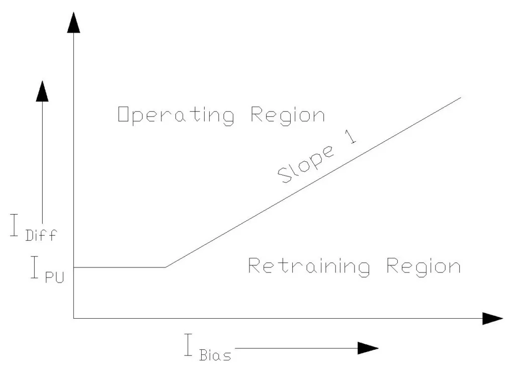
Early relays used a single-slope characteristic, which maintained a straight line at a fixed percentage throughout the operating range (e.g., 50%). This approach was simple to understand and calculate, maintaining a constant percentage throughout the entire operating range.
However, it was inflexible and could not adapt to different current levels. The fundamental drawback was that a relay could not achieve both high sensitivity and security simultaneously. If set at 30% for sensitivity to detect internal faults, it provided inadequate security at high currents when CT saturation was likely to occur.
Dual-Slope Characteristics
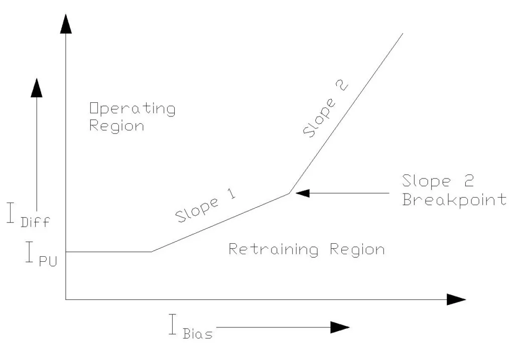
Contemporary numerical relays employ dual-slope (or multi-slope) characteristics that provide two different slopes with automatic switching.
The Slope 1 uses a lower percentage, typically 20-40%, for low to medium restraint currents. The Slope 2 uses a higher percentage, typically 50-80%, for high restraint currents. The Inflection Point (Boundary) represents the restraint current level where switching occurs, typically set at 100-300% of transformer rated current.
This configuration provides multiple advantages: high sensitivity at low currents (Slope 1), high security at high currents (Slope 2), and automatic switching for optimal performance across all current levels.
Modern relays can even use 3-5 slopes for even finer control in critical applications requiring maximum precision.
Practical Example for Single and Dual Slope Characteristics
Situation 1: Normal Load
Imagine the transformer is carrying 100 Amps on the primary side and 100 Amps on the secondary side (perfect balance). However, nothing is perfect! Due to CT errors and other factors, the primary actually measures 100.5 Amps (slight measurement error), and the secondary measures 99.8 Amps (different measurement error). This creates a mismatch of 0.7 Amps (this is the “differential current”) and an average current of 100.15 Amps (this is the “restraint current”).
Now, with SLOPE 1 (Strict Rule) set at 30%, the rule says: “If mismatch exceeds 30% of average current, it’s a fault.” The required mismatch to trip is 30% × 100.15 = 30 Amps. However, the actual mismatch is only 0.7 Amps, so the result is NO TRIP—which is correct! This is normal operation. The sensitivity is high because with Slope 1 = 30%, even a mismatch of 30 Amps would trigger the relay. This catches small internal faults quickly.
Situation 2: External Fault (Lightning Strikes the Transmission Line Far Away)
Now imagine lightning strikes somewhere far from the transformer on the power grid. A huge fault current flows through the entire system: the primary current suddenly jumps to 10,000 Amps (external fault), and the secondary current should also be 10,000 Amps (it’s a through-fault, not inside).
But here’s the problem: Current Transformer Saturation! The HV CT can’t handle 10,000 Amps secondary current accurately. It tries to produce 166.7 Amps (10,000 ÷ 60 ratio), but the CT SATURATES and can only produce 50 Amps instead. Meanwhile, the LV side CT produces 62.5 Amps correctly (10,000 ÷ 160). This creates a mismatch of 62.5 – 50 = 12.5 Amps (FALSE DIFFERENTIAL DUE TO SATURATION!) with an average current of 56.25 Amps.
Now here’s where it gets interesting. If we still used SLOPE 1 (30%), the required mismatch to trip would be 30% × 56.25 = 16.9 Amps. The actual mismatch is 12.5 Amps, so the relay would NOT TRIP (Good! External fault rejected). However, imagine saturation is worse: the HV CT only produces 40 Amps. Then the mismatch becomes 62.5 – 40 = 22.5 Amps. Required to trip with Slope 1 = 30% × 56.25 = 16.9 Amps. Actual mismatch = 22.5 Amps > 16.9 Amps, so the relay WOULD TRIP—this is a FALSE TRIP! This is bad!
This is where SLOPE 2 comes to the rescue! With DUAL SLOPE at high currents, we switch to SLOPE 2 (60%). The required mismatch to trip becomes 60% × 56.25 = 33.75 Amps. The actual mismatch is 22.5 Amps, which is less than 33.75 Amps, so the relay does NOT TRIP—Correct! We avoided the false trip.
Key Operating Zones on the Characteristic Curve
The slope characteristic divides the relay’s response area into distinct zones. The Pickup Threshold Zone represents the region below the lowest point on the slope where there is no operation, and the relay remains stable. Above Slope 1 and below the inflection point lies the Low Current Operating Zone, where internal faults with low current cause the relay to TRIP immediately. At the inflection point itself is the Transition Zone where switching from Slope 1 to Slope 2 occurs automatically. The High Current Operating Zone sits above Slope 2 after the inflection point, where the relay TRIPs if a truly internal fault is present but remains stable for through-faults with CT saturation. Finally, the Unrestrained Zone appears above the maximum differential line, where the relay TRIPS regardless of the restraint current level, providing backup protection for extreme fault currents.
Practical Slope Setting Calculations
Real-World Example: 50 MVA Transformer Differential Protection
Let’s work through a complete practical example to understand how slope operates in real power system installations. Consider a transformer with these specifications: 50 MVA rating, 132 kV / 33 kV voltages (Delta/Wye connection), HV Side CT with 300:5 ratio (CT Ratio = 60:1), and LV Side CT with 800:5 ratio (CT Ratio = 160:1).
Step 1: Calculate Transformer TAP Setting
The TAP represents the secondary current that corresponds to transformer rated current. The formula is:
\(TAP \ (Amps) = \frac{Transformer \ MVA \times 1000}{\sqrt{3} \times Voltage(kV) \times CT \ Ratio}\)
For the HV side: TAP = (50 × 1000) / (√3 × 132 × 60) = 50,000 / 13,717.4 = 3.65 A
For the LV side: TAP = (50 × 1000) / (√3 × 33 × 160) = 50,000 / 9,145.6 = 5.47 A
Step 2: Calculate Minimum Pickup Setting
The minimum pickup must accommodate several factors: transformer magnetizing current (typically 0.5-1% of TAP), no-load current effects, and CT accuracy errors at nominal current (0.5-1%). The recommended approach is to set Pickup = 0.2 to 0.3 × TAP.
For our example, Pickup = 0.25 × 3.65 = 0.91 A (we would round this to 1.0 A for practical implementation).
Alternatively, we can calculate it based on allowed errors:
Pickup = (Magnetizing % + CT Error %) × Average TAP = 2% × 4.56 = 0.91 A.
This alternative method provides a more rigorous approach by explicitly accounting for all error sources.
Step 3: Calculate Slope 1 (Initial Slope) Setting
Slope 1 must be set to account for all steady-state and proportional error sources that can create differential current during normal operation and external faults.
The on-load tap changer (OLTC) can vary by ±10% from nominal, creating a 10% contribution to the slope. Current transformers have ratio errors that increase with current; at 5× nominal current (realistic for external faults), CT errors typically reach 3% on each winding. Modern numerical relays introduce measurement errors during their calculations, contributing approximately 5% due to digitization, phasor calculation approximations, and filtering effects.
When we stack these error sources in a worst-case scenario: 10% + 3% + 5% = 18%. To provide additional safety margin against unforeseen conditions, we round up: Recommended minimum Slope 1 = 25-30%.
Using 30% is a practical choice that ensures protection security while maintaining reasonable sensitivity.
Step 4: Calculate Slope 2 (Secondary Slope) Setting
Slope 2 provides additional security against transient CT saturation during external faults with high through-current. The appropriate value depends on CT quality and characteristics.
- For good quality CTs (Class C or C200), use 50-60%.
- For standard CTs (Class 1.0), use 60-70%.
- For older or lower-grade CTs, use 70-80%.
For our 50 MVA transformer with modern CTs, we would select Slope 2 = 60%, which provides good balance between sensitivity and security.
Step 5: Determine Slope Boundary Point
The slope boundary is the restraint current level where the relay switches from Slope 1 to Slope 2. Generally, this should be set at 1.0 to 3.0 times the rated current in relay secondary.
For more sensitive protection at moderate currents, we recommend:
Boundary = 1.5 × Average TAP = 1.5 × 4.56 = 6.84 A.
This boundary point ensures that the relay uses high sensitivity (Slope 1) during normal load conditions while switching to security-oriented Slope 2 when current levels rise significantly.
Summary of Calculated Settings
The final differential protection settings for our 50 MVA transformer would be presented in the following table, which represents a carefully balanced configuration that provides rapid detection of internal faults while maintaining security against false trips from external disturbances:
| Parameter | Setting | Unit |
|---|---|---|
| Minimum Pickup (87M) | 1.0 | A |
| Slope 1 | 30 | % |
| Slope 2 | 60 | % |
| Slope Boundary | 6.84 | A |
| High Set (Unrestrained) | 8-10 | A |
| Harmonic Block | 15-20 | % |
Error Sources and Why They Matter
1. Current Transformer (CT) Ratio Errors
Current transformer accuracy classes define maximum error at different current levels.
A Class 0.2 CT provides ±0.2% error at rated current, Class 0.5 provides ±0.5% error, and Class 1.0 provides ±1% error at rated current. However, as current increases, these errors grow significantly. At 5 times the rated current, errors increase to approximately 3%. At 10 times rated current, errors reach 5%. At 20 times rated current, errors can rise to 10% or even higher. These high-current errors occur precisely when external faults are most severe and most likely to cause CT saturation.
The practical significance of this becomes clear when considering differential protection. When HV and LV CTs have different accuracy classes or are operating at different multiples of their rated current, the mismatch creates differential current even for through-faults outside the protected zone. This is why matching CT classes and carefully selecting CT ratings is critical for reliable differential protection.
A 3% error on one side combined with a 3% error on the other side can create total mismatches of 6% or more, requiring correspondingly higher slope settings to maintain security.
2. On-Load Tap Changer (OLTC) Variation
On-load tap changers adjust transformer winding turns ratio to regulate voltage during load conditions. The typical variation range is ±10% of nominal turns ratio. When the tap changer operates during normal operation, it changes the transformer winding turns ratio, but the CT ratios designed for nominal tap remain constant. This creates a mismatch that produces differential current proportional to the through-current.
For example, if a transformer is originally set at tap position 16 (nominal) and then changes to tap position 18 (10% higher), the HV voltage increases by 10%, but the CT ratio remains unchanged. If a through-current of 200 A is flowing at the new operating point, the mismatch creates approximately 20 A of false differential current. Without accounting for tap variation in the slope setting, the relay might trip when the OLTC operates, causing unnecessary outages during normal load management operations.
This is why including ±10% tap variation is mandatory in every slope calculation.
3. Current Transformer Saturation (CT Saturation)
Current transformer saturation occurs when the iron core of a CT saturates due to magnetic flux density exceeding the core’s capability. This typically happens during high fault currents, especially when the fault current has a significant DC offset (which is common in AC power systems).
Imagine an external fault producing 50,000 A at the fault location. The HV CT should produce 50,000 / 60 = 833 A in its secondary. However, once the CT saturates (which happens quickly with high current), it can only produce perhaps 20 A before the core reaches saturation. This creates a massive false differential current of 833 – 20 = 813 A! Without proper slope settings to account for this saturation effect, the relay would definitely trip on this external fault. This is the primary reason for using Slope 2 at high current levels to maintain security against such transient CT saturation effects.
4. Transformer Magnetizing (Inrush) Current
When a transformer is energized, current must flow into the primary winding to establish the magnetic flux in the core. This magnetizing current is required even with the secondary winding open-circuited. The distinctive characteristic of inrush current is its high second harmonic component, which can be 20-65% of the fundamental frequency current. The magnitude can reach 2-5 times the transformer rated current at peak, and this condition can persist for several seconds during the energization transient.
Modern relays use harmonic restraint logic to distinguish between transformer inrush (which contains high 2nd harmonic content) and true internal faults (which contain primarily fundamental frequency current with minimal harmonic content). When the relay detects that 2nd harmonic current exceeds a threshold (typically 15-20%), it blocks the trip decision, allowing the transformer to energize without false tripping. This harmonic restraint feature is essential for sensitive differential protection, as it allows the relay to detect faults quickly while ignoring the false signals created by normal energization transients.
5. Measurement and Rounding Errors
Modern numerical relays introduce small errors during their calculations and measurements. Analog-to-digital conversion introduces quantization errors of approximately 1%. The phasor calculation used to convert sampled waveforms into current magnitude and phase introduces approximation errors of about 1%. Time synchronization errors add another 0.5%, and the digital filtering used to remove noise contributes 1-2% of error. When we sum these error sources, the total measurement error typically reaches 5%, which must be included in the slope calculation.
These small errors might seem insignificant individually, but when combined with other error sources (CT errors, tap variation, relay errors), they can affect relay performance. This is why modern relay settings typically include a 5% measurement error allowance in their slope calculations, and why the total Slope 1 is set conservatively at 25-30% rather than the theoretically minimum 18%.
Advanced Slope Concepts in Modern Relays
Harmonic Restraint and Blocking
The principle of harmonic restraint is straightforward: distinguish between transformer inrush current and internal faults. The implementation in modern relays works as follows: if the 2nd harmonic current exceeds 15-20% of fundamental, the relay BLOCKS the trip decision (assuming the high current is inrush, not a fault). Otherwise, the relay ALLOWS the trip decision to proceed based on the percentage differential logic.
There are several benefits of this approach. Transformers can be energized rapidly without nuisance tripping even when high currents flow. The relay maintains high security against false trips and still detects genuine internal faults within milliseconds.
Many modern numerical relays implement harmonic restraint as their primary defense against inrush, supplemented by slope settings as a secondary defense.
Cross-Phase Blocking and Harmonic Sharing
Traditional harmonic blocking uses a limiting approach where each phase independently checks its harmonic percentage. If any phase has high harmonic content exceeding the threshold, the relay blocks ALL phases from tripping. This approach is very secure and prevents false tripping, but it may miss single-phase faults if they occur during energization of other phases.
Modern relays use an advanced method called harmonic sharing, where harmonic signals from all three phases are summed together for evaluation. This approach provides better discrimination between inrush (which typically affects all three phases similarly) and internal faults (which typically affect only one or two phases in different ways). The harmonic sharing method provides better balance between sensitivity and security, allowing faster detection of genuine faults while still maintaining adequate protection against inrush current false trips.
CT Saturation Detection and Dynamic Response
Modern relays incorporate logic to actively detect CT saturation as it occurs. The relay monitors multiple parameters: the rate of change of current (dI/dt), harmonic content changes, phase angle shifts, and patterns from secondary injection test data. When CT saturation is detected, the relay responds dynamically by temporarily increasing slope (adding additional margin), switching to Slope 2 earlier than normal, or delaying the trip decision by 1-2 cycles to verify that the condition is a genuine fault and not a transient.
Common Slope Setting Errors and How to Avoid Them
1: Setting Slope Too Low (Excessive Sensitivity)
Setting Slope 1 at 10-15% represents a fundamental error that prioritizes sensitivity at the expense of security. Engineers sometimes make this mistake because they want maximum sensitivity for fault detection or because they underestimate the magnitude of error sources that occur during real faults. There is often pressure to avoid any perception of protection being “too slow,” which leads to overly aggressive sensitivity settings.
2: Setting Slope Too High (Inadequate Sensitivity)
Setting Slope 1 at 60-80% or using Slope 2 for the entire operating range represents the opposite extreme, over-emphasizing security at the expense of sensitivity. This typically happens when engineers take an overly conservative approach without proper calculation, or when there is organizational distrust of relay performance based on past bad experiences. Cost-cutting measures sometimes lead to skipping proper engineering analysis, resulting in conservative default settings.
3: Ignoring CT Saturation Analysis
Many installations make the critical error of not performing CT saturation analysis, assuming that calculated settings will work correctly in the field. This error happens because CT saturation analysis requires specialized software tools or expertise that may not be available. The IEEE PSRC CT Saturation Calculator is freely available but requires understanding how to use it properly. Cost-cutting sometimes leads to skipping this analysis step entirely.
4: Not Accounting for On-Load Tap Changer (OLTC)
Many protection engineers design systems that fail to account for on-load tap changer variation, typically assuming that tap changes are rare or don’t significantly affect the protection. This misunderstanding leads to settings that are inadequate for real-world transformer operation where OLTC adjustments happen regularly to maintain voltage stability.
5: Inadequate Field Testing
The most critical error is applying calculated settings to a relay without performing secondary injection testing to verify that the settings actually work as expected. Many engineers assume that if the calculations are correct, the relay will automatically respond correctly. However, relay configuration errors, software bugs, or misunderstandings about how relay settings map to actual performance can cause discrepancies between theory and practice.
Prevention requires using certified relay test sets (Omicron 356, Doble F6150, or equivalent devices) before commissioning. Perform comprehensive slope testing at multiple points: below Slope 1 (verify no trip), on Slope 1 (verify trip boundary), above Slope 1 (verify trip), at inflection point (verify transition), on Slope 2 (verify transition zone), and above Slope 2 (verify high-current zone). Document all test results in detail. Obtain relay manufacturer approval of the test results before placing the relay in service.
Slope Settings for Different Equipment
Transformer Differential Protection
Power transformer differential protection typically uses Slope 1 settings in the range of 25-35% to account for the on-load tap changer variation and current transformer errors inherent in power transformer installations. Slope 2 typically ranges from 60-75% to prevent false trips at high through-currents when CT saturation is likely. The slope boundary should be set at 1.5-2.0 times the transformer TAP value to provide transition at currents typical of external faults. The pickup setting should be approximately 0.25 times the TAP to accommodate the transformer magnetizing current.
Generator Differential Protection
Generator differential protection requires lower Slope 1 settings, typically 15-25%, because generators have fewer error sources than transformers—there is no on-load tap changer to create variation, and the CT configuration is simpler. Slope 2 can be set lower (40-60%) than transformer protection because generator applications typically have less severe CT saturation during external faults. The slope boundary should be set lower (1.0-1.5× TAP) because generator faults typically produce very high currents compared to transformer faults. The pickup setting can be lower (0.1-0.2× TAP) because generators have lower magnetizing current than transformers.
Bus Bar Differential Protection
Bus bar differential protection requires the highest slope settings because multiple incoming and outgoing circuits create the most error sources—each circuit contributes its own CT errors, and multiple CTs must be matched. Slope 1 typically ranges from 30-40% while Slope 2 ranges from 70-85%. The slope boundary is set higher (2.0-3.0× maximum load current) because bus bar faults are rare and when they occur, they produce very high currents.
Motor Differential Protection
Large motors (greater than 5 MVA) require differential protection to detect internal winding faults. Slope 1 typically ranges from 20-30% while Slope 2 ranges from 50-70%. The slope boundary should be set at 1.0-1.5 times the motor TAP because motor starting inrush currents are very high (5-7 times rated current), and we want the relay to switch to Slope 2 at these high starting currents.
Testing and Verification of Slope Settings
Secondary Injection Testing Procedure
Before commissioning any differential protection scheme, thorough secondary injection testing must be performed using proper relay test equipment. The equipment needed includes a portable relay test set (Omicron 356, Doble F6150, or equivalent instruments capable of injecting precise current), test leads and current injection cables rated for the relay current ranges, and standard test specifications from the relay manufacturer documentation.
Step 1: Perform Pickup Test
Begin by injecting differential current equal to Pickup × 0.9 (slightly below the pickup threshold). Verify the relay does NOT trip—this confirms that the pickup setting provides adequate immunity to small currents.
Then increase the injection to Pickup × 1.1 (slightly above the pickup threshold) and verify the relay DOES trip.
Repeat this test multiple times to confirm consistent performance, and document the exact pickup current where the relay switches from “no trip” to “trip” status. Calculate the actual pickup versus the setting and verify they match within ±5% accuracy.
Step 2: Perform Slope 1 Test
Set the restraint current to 1.0 A in the test set. Inject differential current equal to Slope 1 × 0.9 (below the slope line at this restraint current). Verify the relay does NOT trip.
Then increase differential to Slope 1 × 1.1 (above the slope line) and verify the relay DOES trip. This test confirms that the relay operates correctly at the first slope line.
Repeat this test at 3-4 different restraint current levels (1A, 2A, 4A, 6A) to verify that the slope characteristic remains consistent across the entire low-current operating range.
Step 3: Perform Slope 2 and Boundary Test
At a restraint current just below the boundary point, verify that the relay operates according to Slope 1 characteristics. Then increase the restraint current to just above the boundary and verify that the relay now operates according to Slope 2 characteristics with the higher slope percentage.
This tests the critical transition point where the relay switches from high sensitivity (Slope 1) to high security (Slope 2).
Verify that the transition is smooth with no gaps or discontinuities in the characteristic curve.
Step 4: Perform High-Current (Unrestrained) Test
Set the differential current above the unrestrained setting (typically 8-10 A in secondary). Verify the relay TRIPS regardless of restraint current level. This confirms the backup protection feature functions correctly.
The test report should document all test results in a clear table format showing test point identification, restraint current, differential current, expected result, actual result, and pass/fail status for each test point.
| Test Point | Restraint (A) | Differential (A) | Expected Result | Actual Result | Pass/Fail |
|---|---|---|---|---|---|
| Pickup-1 | N/A | 0.9× Pickup | No Trip | No Trip | ✓ Pass |
| Pickup-2 | N/A | 1.1× Pickup | Trip | Trip | ✓ Pass |
| Slope1-1 | 2 | 0.6 | No Trip | No Trip | ✓ Pass |
| Slope1-2 | 2 | 0.66 | Trip | Trip | ✓ Pass |
Conclusion
The differential protection slope is far more than just a technical setting, it represents the intelligent balance between protection sensitivity and security that underlies modern power system reliability. Engineers and technicians who develop deep understanding of slope characteristics can optimize protection performance by designing schemes that protect equipment rapidly and effectively while minimizing false tripping during external disturbances. This selective protection ensures that only faulted equipment is disconnected, preventing cascading outages that could affect thousands of customers.