The Master Trip (86) Relay is a auxiliary control component in electrical power system protection schemes that serves as the primary switching mechanism between protective relays and circuit breaker trip coils. This relay is often referred to as the “lockout relay” or “trip relay” in electrical protection terminology. It acts as an intermediate device that receives operating signals from protection relays and commands circuit breakers to open during fault conditions.
In this technical guide we will discuss the Master Trip (86) Relay’s definition, function, operation principles, wiring diagrams, applications, advantages, and real-world examples suitable for electrical engineering students and professionals.
Definition and Basic Concept
A Master Trip Relay (ANSI Function 86) is an instantaneous auxiliary relay that receives trip signals from various protective relays and converts them into a circuit breaker trip command. In simpler terms, it acts as a “messenger” between detection devices (like differential relays and overcurrent relays) and the circuit breaker that needs to be opened during a fault.
The Master Trip Relay operates on a simple electromagnetic principle where a small DC coil current (typically 110V, 220V, or 48V DC) energizes an electromagnet that mechanically closes contacts. These contacts then complete the circuit to the circuit breaker’s trip coil, causing the breaker to open and isolate the faulted section from the healthy network.
Why Master Trip Relay is Needed
In modern electrical substations and power plants, there are several reasons to use a Master Trip Relay:
1. Isolation and Protection
The protective relay’s output contacts may not have sufficient current capacity to directly energize a circuit breaker’s trip coil. A Master Trip Relay acts as a buffer, ensuring that the protective relay contacts are not overloaded.
2. Reliability
Using a dedicated Master Trip Relay improves overall system reliability by ensuring that multiple protection relays can trip the same circuit breaker through a single consolidated point. This reduces wiring complexity and provides a single point of control.
3. Redundancy
In critical systems, multiple Master Trip Relays can be used in parallel or series configurations to provide backup tripping capability. If one relay fails, the other can still command the trip action.
4. Coordination
Master Trip Relays allow multiple protective relays to coordinate their actions through logic gates and switching schemes for selective and fast fault isolation.
Main Components of a Master Trip Relay
A typical Master Trip Relay consists of the following key components:
1. Electromagnet Coil
This is the primary operating element that consists of a coil of wire wound around an iron core. When DC current is supplied to this coil, it creates a magnetic field that attracts a movable armature or plunger.
The coil is designed to operate reliably at its rated voltage (typically 48V DC, 110V DC, or 220V DC) and rated current.
2. Armature Assembly
The armature is a movable iron piece that is attracted to the electromagnet when the coil is energized. As the armature moves toward the electromagnet, it mechanically operates the contact assembly.
The armature has a return spring that pulls it back to its original position when the coil is de-energized.
3. Contact Assembly
The contact assembly includes the actual electrical contacts that open and close the circuit. A Master Trip Relay typically has two types of contacts:
- Normally Open (NO) Contacts: These contacts are open when the relay coil is de-energized and close when the coil is energized. These are the main contacts used to energize the trip coil of the circuit breaker.
- Normally Closed (NC) Contacts: These contacts are closed when the relay coil is de-energized and open when the coil is energized. These contacts are often used for auxiliary functions like indicating the relay status or for fail-safe applications.
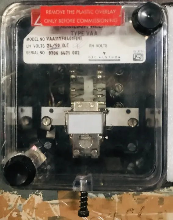
4. Terminal Block and Connections
The relay has clearly marked terminals for the coil connections (coil + and coil -) and the contact connections. These terminals are designed for easy and secure wiring to the protection circuit.
5. Enclosure
The entire relay is housed in a protective enclosure made of ceramic or plastic material. This enclosure provides mechanical protection, insulation, and allows the relay to be mounted on a DIN rail or panel in the control cabinet.
Relay Specifications and Ratings
When selecting a Master Trip Relay, the following specifications are important:
| Specification | Typical Range | Importance |
|---|---|---|
| Coil Voltage | 48V DC, 110V DC, 220V DC, 24V DC | Must match substation control voltage |
| Coil Current | 50-150mA at rated voltage | Indicates power requirement for operation |
| Contact Voltage Rating | 250V AC / 110V DC or higher | Must exceed circuit breaker trip voltage |
| Contact Current Rating | 2A to 10A continuous | Must exceed circuit breaker trip coil current |
| Operating Time | 15-50 milliseconds | Speed of response to trip command |
| Contact Arrangement | SPDT, DPDT, 4PDT | Flexibility for different protection schemes |
| Mechanical Life | 100,000+ operations | Durability and long-term reliability |
How Master Trip Relay Works: Operation Principle
To understand the operation of a Master Trip Relay, let us follow what happens when a fault occurs in the power system:
Step 1 – Fault Occurs
When a three-phase short circuit or other fault occurs on a transmission line or in a substation, the protective relays immediately detect this abnormal condition by monitoring the current, voltage, or impedance of the circuit.
Step 2 – Protective Relay Picks Up
The protective relay (such as an overcurrent relay, distance relay, or differential relay) measures the fault current and determines that it exceeds the pre-set threshold.
The relay’s detection logic, whether based on electromagnetic coils or microprocessor algorithms, initiates a trip command.
Step 3 – Relay Output Contacts Close
When the protective relay detects the fault condition, its output contacts close. This action completes a DC circuit from the battery to the Master Trip Relay coil.
The DC voltage (typically 110V or 220V) from the battery now flows through the Master Trip Relay coil.
Step 4 – Master Trip Relay Coil Energization
As soon as current flows through the Master Trip Relay coil, the electromagnet becomes active. The magnetic field created by the energized coil attracts the movable armature toward the electromagnet’s magnetic field.
Step 5 – Mechanical Movement and Contact Closure
The attraction between the electromagnet and the armature causes the armature to move, typically in a very short time of 15-50 milliseconds. As the armature moves, it mechanically pushes or pulls the contact assembly, causing the Normally Open contacts of the Master Trip Relay to close.
Step 6 – Trip Coil Energization
With the Master Trip Relay’s contacts now closed, the circuit from the DC battery through the trip coil of the circuit breaker is completed. Current now flows into the trip coil of the circuit breaker.
Step 7 – Circuit Breaker Opening
The trip coil of the circuit breaker is an electromagnet similar to the Master Trip Relay coil. When current from the battery flows through the trip coil, the electromagnet creates a magnetic force that mechanically trips the breaker mechanism.
This action causes the main contacts of the circuit breaker to open, interrupting the fault current.
Step 8 – Fault Isolation
Within milliseconds of the fault occurring, the faulted section of the power system is isolated from the healthy network. The fault current is interrupted, protecting equipment from damage and preventing the fault from affecting other parts of the system.
Step 9 – De-energization and Reset
Once the breaker opens and the fault current is interrupted, the protective relay de-energizes (unless it is configured to remain latched). When the protective relay coil loses power, its contacts open, de-energizing the Master Trip Relay coil. Without coil current, the electromagnet loses its magnetic force, the armature returns to its original position due to the spring force, and the Master Trip Relay contacts return to their de-energized state.
Types of Master Trip Relays
1. Electromagnetic Master Trip Relays
Electromagnetic relays are the traditional and most widely used type in power systems. These relays use electromagnetic principles to operate and have been the industry standard for decades.
Advantages of Electromagnetic Relays:
- Highly reliable and time-proven design with decades of field experience
- Simple construction with fewer components requiring maintenance
- Inherent immunity to electrical noise and electromagnetic interference
- Fail-safe operation due to mechanical spring return
- Lower cost compared to digital alternatives
- Manual operation capability in case of power loss
Disadvantages:
- Slower response time (15-50 milliseconds) compared to electronic relays
- Requires larger physical space in control cabinets
- Contacts may wear out over time with frequent operation
- Limited flexibility in logic implementation for complex protection schemes
2. Auxiliary Trip Relays vs. Master Trip Relays
While the terms are sometimes used interchangeably, there is an important distinction:
Master Trip Relay specifically refers to the main relay that directly controls the trip coil of the circuit breaker. It is the primary tripping mechanism.
Auxiliary Trip Relays are supplementary relays used in complex protection schemes where multiple functions need to be coordinated. These might include:
- Permissive trip relays that only allow tripping under certain conditions
- Blocking relays that prevent tripping during safe conditions like power swings
- Synchronizing relays that coordinate tripping actions between multiple relays
In modern microprocessor-based protection relays, these auxiliary functions are often integrated into the relay software, eliminating the need for separate physical relays.
3. Single-Pole vs. Multi-Pole Master Trip Relays
Single-Pole Relays (SPDT – Single Pole Double Throw):
These have one moving contact that can connect to either of two fixed contacts. They are used in simple protection schemes where a single trip command is needed.
Multi-Pole Relays (DPDT – Double Pole Double Throw, or 4PDT – Four Pole Double Throw):
These have multiple independent contact sets that move together when the coil is energized. Multi-pole relays are used in complex schemes where:
- Multiple circuit breakers need to be tripped simultaneously
- Auxiliary functions like alarm indication or breaker status signaling are needed
- Redundant trip paths are required for critical applications
Typical Specifications for Industrial Master Trip Relay (86):
- Coil Voltage: 24 VDC, 48 VDC, 110 VDC, or 220 VDC (most common in modern systems: 24 VDC or 48 VDC)
- Coil Power: 2-5 watts
- Response Time: 10-30 milliseconds (subcycle operation)
- Contact Rating: Usually 2-5 amperes at rated voltage
- Number of Contacts: Typically 2-4 NO/NC contact pairs
- Holding Current: Designed to remain energized until fault is cleared
- Reset Time: Nearly instantaneous when de-energized

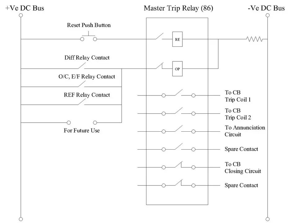
Master Trip Relay Wiring Diagram
The detailed wiring diagram showing complete circuit connections, including DC power supply, protective relay inputs, relay coil, trip contacts, circuit breaker coil, and auxiliary indication circuits is provided below.
How Protective Relays Command Master Trip Relay
Different types of protective relays interact with the Master Trip Relay in a coordinated manner:
1. Overcurrent Relays (ANSI 51/50)
Overcurrent Relays monitor the current flowing through a circuit. When the current exceeds a pre-set threshold for a specific duration (delayed) or instantaneously, the relay contacts close, sending a trip signal to the Master Trip Relay.
For example, an overcurrent relay protecting a transformer might be set to trip at 1.5 times the transformer’s rated current.
2. Distance Relays (ANSI 21)
These relays measure the impedance of the protected line and are organized into protective zones. When a fault occurs, the relay calculates the apparent impedance and determines which zone the fault is in.
Zone 1 operates instantaneously, while zones 2 and 3 have intentional time delays.
The relay output to the Master Trip Relay depends on which zone is activated.
3. Differential Relays (ANSI 87)
Differential Relays compare currents entering and leaving a protected element (transformer, generator, or bus). When the difference exceeds a threshold, indicating an internal fault, the relay instantly commands the Master Trip Relay to trip the circuit breaker protecting that element.
4. Ground Fault Relays (ANSI 51N/50N)
Ground Fault Relays specifically monitor ground fault currents. They are often used alongside phase overcurrent protection to provide comprehensive protection against all types of faults.
Real-World Applications and Examples
Scenario: Consider a 33 kV distribution feeder supplying power to an industrial area. The feeder is protected by an overcurrent relay set to trip at 800 amperes with a time dial setting that gives 0.1 seconds operating time at this current level.
What Happens During a Fault:
- A three-phase short circuit occurs on the feeder due to a downed transmission line conductor
- The fault current immediately rises to 2000 amperes
- The overcurrent relay detects this current and closes its output contacts within milliseconds
- The relay’s contacts complete the DC circuit to the Master Trip Relay coil
- The Master Trip Relay electromagnet energizes and its contacts close within 20 milliseconds
- Current flows from the 110V DC battery through the circuit breaker’s trip coil
- The circuit breaker opens within 50 milliseconds of the fault occurring
- The fault is isolated, protecting downstream equipment and preventing widespread blackout
Testing and Commissioning of Master Trip Relays
When a Master Trip Relay is commissioned or during preventive maintenance testing, the following checks are performed:
Visual Inspection:
- Check for physical damage, corrosion, or loose connections
- Verify that the relay is properly mounted and secured
- Inspect the coil and contact assembly for visible defects
Insulation Resistance Test:
- Using a megohmmeter, measure the insulation resistance between the coil and ground
- Typical acceptable values are greater than 100 MΩ (megaohms)
- This test ensures there are no insulation breakdowns or moisture ingress
Coil Resistance Test:
- Measure the DC resistance of the relay coil using a precision ohmmeter
- Compare the measured value with the relay’s nameplate specifications
- A significant deviation (more than 5-10%) might indicate coil winding damage
Pick-Up Test (Energization Test):
- Apply the rated voltage to the relay coil and listen for the characteristic “click” sound of the relay operating
- Verify that the relay operates at or below the rated voltage
- Measure the coil current at rated voltage and compare with specifications
Contact Continuity Test:
- Using a multimeter, verify that the Normally Open contacts close when the relay coil is energized
- Verify that the Normally Closed contacts open when the relay coil is energized
- Check contact resistance, which should be very low (typically less than 1 ohm)
Timing Test:
- Using a high-speed timer and oscilloscope, measure the operating time from when coil voltage is applied to when the contacts actually close
- Typical operating time should be 15-50 milliseconds depending on the relay model
- If operating time exceeds specifications, the relay may be aging and require replacement
Drop-Out Test:
- After energizing the relay coil, reduce the coil voltage gradually until the relay de-energizes
- The relay should drop out at approximately 85-95% of the pick-up voltage
- This test ensures proper coil performance and spring mechanism
Contact Wear Test:
- After thousands of operations, contact surfaces may wear and accumulate dust or oxidation
- Light contact cleaning with appropriate materials can restore contact quality
- If contact resistance remains high even after cleaning, the relay requires replacement
Conclusion
The Master Trip Relay remains one of the most important and reliable components in power system protection schemes despite the advancement of digital technologies. Its simple electromagnetic design, proven reliability, and fail-safe characteristics make it an essential element in any comprehensive protection system.