Busbar differential protection is the primary method for detecting and isolating faults within the busbar zone of electrical substations using Kirchhoff’s current law principle.
This protection scheme compares the sum of currents entering and leaving the busbar section. When an imbalance occurs, it triggers immediate isolation of the faulty section by tripping associated circuit breakers.
Modern substations employ both centralized and distributed relay architectures to implement this protection with low impedance schemes preferred due to their flexibility in handling complex busbar configurations and better integration with numerical relay.
In this technical guide we will discuss everything about Busbar Differential Protection including working principle, high impedance and low impedance busbar protection, main and peripheral units, relay settings, testing and commissioning.
1. Busbar Differential Protection Fundamentals
1.1 Why Busbar Protection is Important?
The busbar is the backbone of any electrical substation. Busbars can experience faults due to insulation breakdown caused by moisture, pollution, mechanical damage, or human error during maintenance activities.
The consequences of an unprotected busbar fault are severe. Sustained high-magnitude fault currents cause thermal and mechanical damage to switchgear, generate dangerous arc flash hazards that threaten personnel safety, and can destabilize the entire power system by disrupting supply to multiple transmission lines and distribution circuits simultaneously connected that busbar.
A single busbar fault affecting a transmission-level busbar could cause cascading outages across a wide geographical region.
Therefore, the protection standard requires busbar fault clearance within 100-200 milliseconds to prevent equipment damage and maintain system stability.
Busbar differential protection achieves this requirement by providing instantaneous, high-speed fault detection without relying on time-graded backup protection.
1.2 Kirchhoff’s Current Law
Busbar differential protection operates on Kirchhoff’s current law (KCL), which states that the algebraic sum of currents flowing into a node must equal zero during steady-state conditions.
When applied to busbar protection, this principle means that all currents entering the protected busbar zone must equal all currents leaving the zone under normal operating conditions.
1.3 Working Principle of Busbar Protection
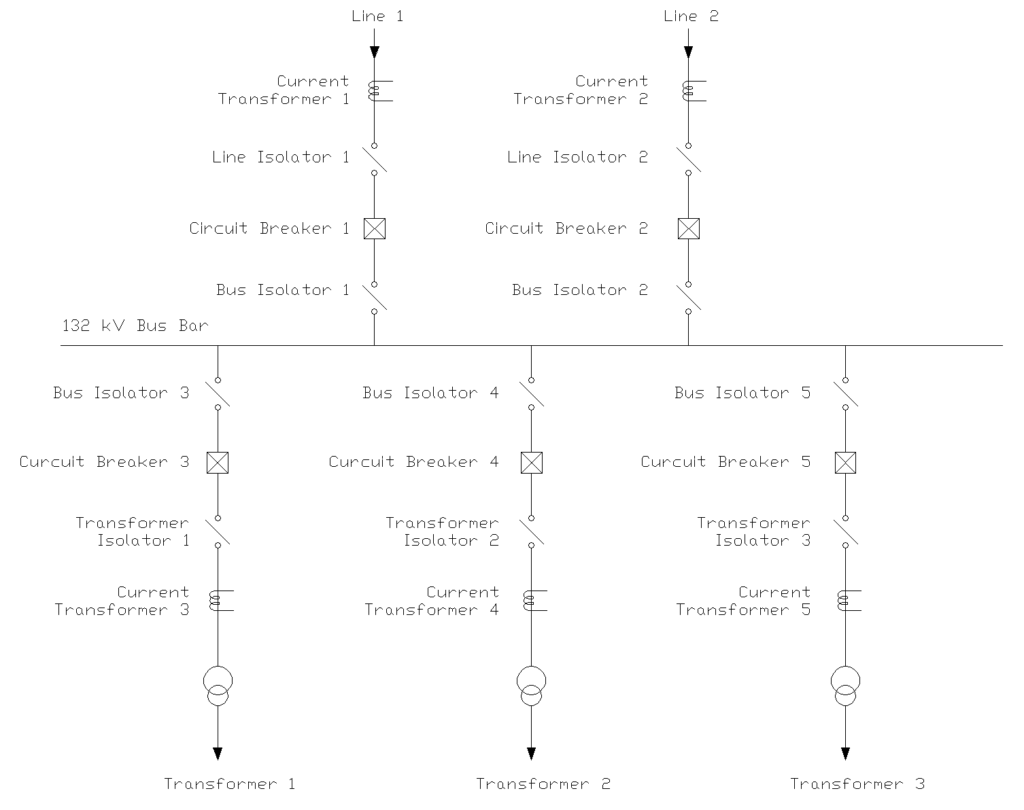
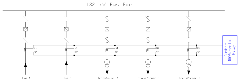
Current transformers (CTs) are installed on every circuit connected to the busbar including incoming lines, outgoing feeders, transformer primary circuits, and bus couplers. These CTs continuously monitor the current magnitude and direction and converts primary currents to lower secondary currents for relay processing.
1.3.1 During Normal Operation
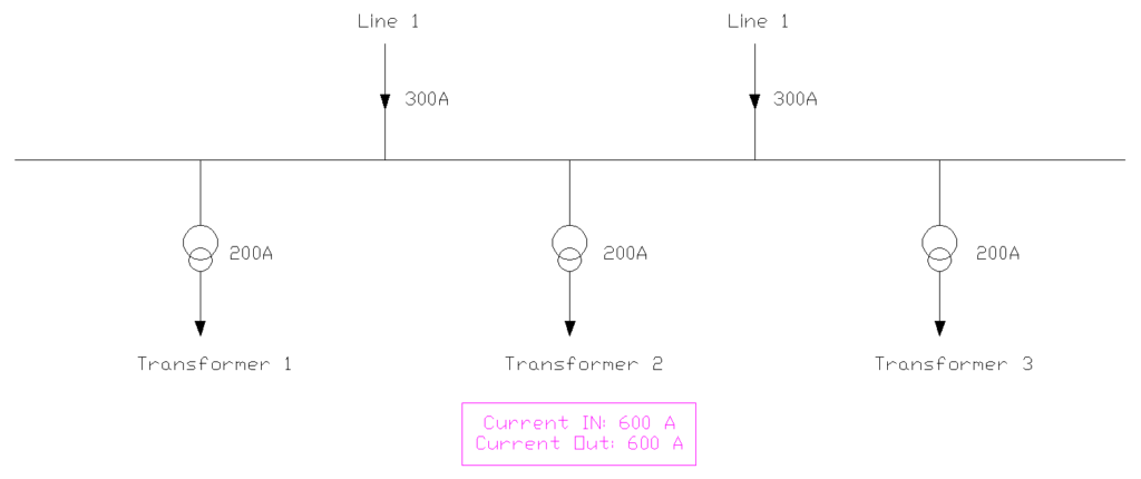
During normal operation, the relay receives secondary currents from all CTs connected to the protection zone. The protection relay electronically sums these currents with their polarities and magnitudes. When the algebraic sum of all secondary currents equals zero (or remains below a very small threshold), the relay remains stable and no trip signal is issued.
1.3.2 During Fault Condition
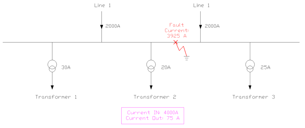
However, the moment a fault develops within the busbar zone such as a phase-to-phase short circuit or a phase-to-ground fault, the current balance is disrupted.
Fault current flows from healthy sources toward the fault point. This creates a net imbalance in the differential circuit. This unbalance produces a non-zero differential current.
If this differential current exceeds the relay pickup threshold setting, the busbar differential protection relay operates instantaneously and issue trip commands to all circuit breakers connected to the faulted busbar section.
2. Busbar Protection Zones
2.1 Protection Zone
A busbar protection zone is the physical region containing the busbar conductor and all primary equipment directly connected to it up to the circuit breaker terminals.
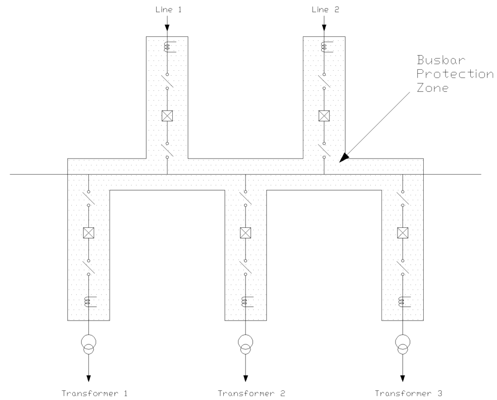
The zone boundaries are defined by the locations of current transformers. All current entering through one set of CTs and exiting through other CTs is considered part of the zone.
In practical substation design, protection zones are assigned based on busbar configuration. In single busbar systems, one protection zone covers the entire busbar. In double busbar or more complex configurations, separate zones are assigned to each busbar section for selective tripping of only the affected busbar while maintaining service to the other busbar section.
For bus couplers, the CTs are typically connected using an “overlapping” configuration so that faults in the coupling section are detected by both adjacent busbar protection zones.
2.2 Dead Zone or Blind Zone
Despite careful CT placement, a “dead zone” or “blind zone” can exist between the CT location and the circuit breaker terminals.
This unprotected region arises because the CT secondary circuits are connected in parallel after the CT itself, yet the primary circuit between the CT and the breaker remains part of the zone.
To address this vulnerability, specialized protection schemes such as dead zone or “teed” protection are employed using additional overcurrent elements within the protection relay.
3. High Impedance Busbar Differential Protection Scheme
3.1 Operating Principle
The high impedance busbar differential protection scheme operates on voltage measurement rather than direct current comparison.
In a high impedance scheme, all current transformer secondary windings are connected in parallel across a high impedance relay element with impedance values ranging from 1000 to 3000 ohms. The relay voltage coil is connected in series with a non-linear resistor called a metrosil or voltage-dependent resistor.
During normal operation and external faults, the CT secondary currents balance out and produces negligible voltage across the relay.
However, when an internal busbar fault occurs, the CT currents no longer balance, and the resulting differential current flows through the high impedance relay which develops a significant voltage to cause relay operation.
When an external fault occurs, one or more CTs might saturate due to heavy through-fault current. A saturated CT effectively becomes a low impedance path. In the high impedance scheme, the relay’s high impedance ensures that most of the differential current created by CT saturation flows through the saturated CT itself rather than through the relay. This means the voltage developed across the relay remains below the pickup threshold, preventing false tripping.
3.2 CT Matching Criteria
The scheme requires careful matching of CT characteristics. All CTs connected to one busbar differential zone must have identical ratios, similar magnetization curves, and matched knee-point voltages.
3.3 Relay Settings
Relay settings for high impedance schemes is based on voltage setting which can be calculated from maximum secondary fault current, CT resistance, and secondary cable resistance.
A typical setting might be 100-200 volts for the relay pickup.
4. Low Impedance Busbar Differential Protection Scheme
4.1 Operating Principle
Low impedance busbar differential protection is the modern standard for busbar protection. This scheme directly compares the currents entering and leaving the busbar zone by measuring the vector sum continuously.
The relay has a low input impedance less than 1 ohm which allows it to accurately measure current rather than voltage.
In a low impedance scheme, each CT secondary winding connects individually to the numerical relay through separate input channels. The relay digitally samples each current input thousands of times per second by converting analog signals to digital values. It then performs mathematical vector summation to calculate the differential current as the algebraic sum of all measured currents.
This provides tremendous flexibility because the relay can handle CTs with different ratios, different characteristics, and different secondary burdens without requiring perfect matching.
4.2 CT Ratio Mismatch
The numerical relay compensates for CT ratio mismatches through software. For example, if one circuit uses a 1000/1A CT while another uses 2000/1A, the relay automatically adjusts the measured values to a common base for comparison. This eliminates the need for auxiliary CTs or interposing transformers that older schemes required.
4.3 Restraining Current & Sensitivity
Low impedance schemes implement percentage bias characteristics to enhance stability. The relay calculates both the differential current and the restraining current.
The restraining current is the average of all currents flowing through the busbar which provides a measure of through-fault magnitude. The relay uses this information to dynamically adjust its sensitivity.
During light load conditions with minimal through-current, the relay operates with high sensitivity to detect even small internal faults. During heavy external faults when CT errors are more likely, the relay automatically becomes less sensitive requiring larger differential current for operation.
5. Central Unit and Peripheral Unit Architecture
5.1 Operating Principle
Modern numerical busbar protection employs a distributed architecture comprising a central unit (CU) that coordinates the protection scheme and multiple peripheral units (PU) located at each feeder, transformer, and coupler connection point.
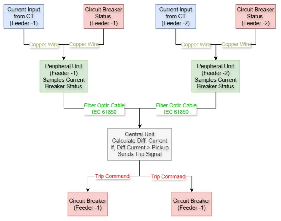
This provides several advantages over centralized architectures where all analog inputs are wired directly to a single relay location. With distributed architecture, each peripheral unit performs local signal acquisition from its associated current transformers and circuit breaker status switches, then transmits only the processed data to the central unit via a communication channel, typically fiber-optic cables.
The central unit receives the processed current signals from all peripheral units and executes the core busbar differential protection algorithm. It continuously calculates the differential current summing all incoming and outgoing currents from the associated zone, compares this differential current against the restraining current, and determines whether a fault condition has developed.
Upon detecting a fault, the central unit calculates which specific zone is affected and determines which circuit breakers must be tripped to isolate the fault. It then sends trip commands back through the communication network to the respective peripheral units, which execute the trip commands by closing the trip relay contacts connected to the circuit breaker trip coils.
5.2 Inter-Unit Communication Protocol
The communication between central and peripheral units follows standardized protocols such as IEC 61850 or proprietary high-speed protocols optimized for protection applications.
Messages typically flow at rates of 100-1000 messages per second. This ensures that the central unit has current information about all peripheral unit statuses and that peripheral units receive trip commands within a few milliseconds of the central unit’s fault detection decision.
Message content includes:
- Current samples: The digital representation of secondary CT currents, typically sent once per power cycle (every 20 milliseconds at 50 Hz)
- Status information: The binary state of circuit breakers, isolator switches, and auxiliary contact signals indicating whether equipment is energized or in-service
- Diagnostic messages: Signals indicating the health of the peripheral unit hardware, communication links, and sensor inputs
- Trip commands: Urgent messages from the central unit commanding specific peripheral units to immediately execute trip relay closures
6. Busbar Differential Relay Settings
6.1 Minimum Pickup Current Setting
The pickup current is the minimum differential current required to cause relay operation. Setting this too low makes the relay sensitive but increases the risk of false tripping due to CT errors during external faults. Setting it too high reduces sensitivity to high-resistance faults on the busbar.
Typical pickup settings range from 0.2 to 0.5 amperes on the relay secondary side. This translates to 20-50 amperes on the primary side for a CT ratio of 1000/1A. The setting should be above the maximum expected differential current due to CT errors during maximum through-fault conditions, yet low enough to detect all credible busbar faults.
6.2 Percentage Bias Characteristic
The percentage bias feature makes the relay less sensitive as through-fault current increases. A typical characteristic might specify 20% bias meaning that the differential current must exceed 20% of the restraining current for operation.
For example, with a 20% slope setting:
- If through-fault current is 100A, differential current must exceed 20A for operation
- If through-fault current is 500A, differential current must exceed 100A for operation
This characteristic provides stability during external faults with CT errors and maintains high sensitivity for internal faults where all current contributes to the differential signal rather than the restraining signal.
6.3 Time Delays
Busbar differential protection typically operates instantaneously within 20-50 milliseconds for clear fault conditions. However, some relays include optional time delays for specific situations:
- Anti-sympathetic inrush delay: A brief delay (perhaps 50-100 milliseconds) might be applied when harmonic content is detected, ensuring the relay can distinguish between faults and transformer inrush
- Coordination delays: In some configurations, a slight delay might coordinate with extremely fast line protection to allow selective clearing of faults right at the busbar boundary
7. Testing and Commissioning
Testing is essential before placing busbar differential protection into service. Testing verifies correct operation, confirms CT polarity and wiring, and validates settings.
7.1 CT Polarity Testing
Correct CT polarity is absolutely important for differential protection. If even one CT is connected with reversed polarity, it will cause false differential current during normal load conditions and might fail to operate during actual faults.
Primary injection testing is the gold standard for verifying CT polarity. A test current is injected into the primary circuit and verify that the resulting secondary current flows in the expected direction through the differential relay.
For existing installations where primary injection is impractical secondary injection combined with careful load current analysis can verify polarity. With load flowing through the busbar, all CT secondary currents should vector sum to approximately zero.
7.2 Stability Testing
Stability testing verifies that the relay doesn’t trip for external faults. This is typically performed through secondary injection simulating maximum external fault current. The relay should remain stable for external faults.
7.3 Sensitivity Testing
Sensitivity testing confirms that the relay operates correctly for internal faults of various magnitudes. Testing should include:
- Minimum pickup testing at threshold differential current
- Phase-to-ground fault simulation
- Phase-to-phase fault simulation
- Three-phase fault simulation
- High-resistance fault testing
Each test verifies both correct operation and appropriate operating time.
7.4 Functional Testing
Beyond basic protection functions, commissioning should verify all supporting features:
- Breaker failure protection initiation and timing
- Check synchronizing functions and permissive logic
- Replica/check-back system functionality
- CT supervision and alarm generation
- Communication interfaces and SCADA integration
- Trip circuit supervision
8. Common Issues and Troubleshooting
Despite careful design and commissioning, busbar differential protection systems occasionally experience problems.
8.1 Nuisance Tripping
Unexplained tripping of busbar protection is serious because it disrupts multiple circuits simultaneously. Common causes include:
- CT circuit issues: Loose connections, deteriorated insulation, or moisture ingress can create intermittent faults in CT circuits
- Settings too sensitive: Pickup or bias settings below optimal values make the relay susceptible to CT errors
- Relay malfunction: Though rare with modern equipment, relay failures can occur
- External interference: Electrical noise from station equipment can sometimes affect relay operation
Investigation requires detailed analysis of relay event records, inspection of CT circuits, verification of settings against original calculations, and sometimes installation of temporary monitoring equipment to capture transient conditions.
8.2 Failure to Trip
Even more serious than nuisance tripping is failure to operate during actual busbar faults. Potential causes include:
- Open CT secondary circuit: A broken wire prevents fault current measurement
- Incorrect CT polarity: Makes internal faults appear as external faults
- Relay desensitized by incorrect settings: Pickup set too high or bias too aggressive
- DC supply failure: Relay cannot issue trip commands without power
- Trip circuit problems: Broken wires or failed auxiliary relays prevent trip signals from reaching breakers
9. Conclusion
Busbar differential protection is one of the most important elements in substation protection schemes. Its ability to detect faults within the busbar zone with high sensitivity and speed makes it indispensable for maintaining power system integrity and preventing extensive damage during fault conditions.