Circuit breakers are one of the most essential protective devices in electrical engineering. They serve as the primary protector of electrical systems protecting equipment, wiring, and most importantly human lives from electrical hazards. Every home, office, factory, and power station relies on circuit breakers for safe and reliable electrical operation.
In this technical guide, we will discuss everything about circuit breakers including their basic definition, working principle, types, components, ratings, applications, installation and testing.
1. What is a Circuit Breaker?
A circuit breaker is an automatically operated electrical switch designed to protect an electrical circuit from damage caused by excess current. This excess current results from overload conditions or short circuits. Unlike a fuse which operates once and then must be replaced, a circuit breaker can be reset either manually or automatically to resume normal operation after the fault condition has been corrected.
Think of a circuit breaker as a pressure cooker’s safety valve. Just as the safety valve automatically releases excess steam when pressure inside the cooker becomes dangerously high to prevent an explosion, a circuit breaker automatically trips and disconnects the electrical supply when current exceeds safe limits to prevent fires, equipment damage, and electrical hazards.
Consider a practical example to understand this better. Imagine you have too many appliances plugged into one circuit in your kitchen with a toaster, microwave, coffee maker, and electric kettle all running simultaneously. The combined current draw exceeds the safe limit of the circuit. The circuit breaker detects this overload condition and automatically trips which cuts off the power supply before the wiring overheats and causes a fire.
2. History and Evolution of Circuit Breakers
The history of circuit breakers dates back to 1879 when Thomas Edison first described the concept of a circuit breaker in his patent application for his electrical distribution system. However, the modern circuit breaker was developed in the early 20th century as electrical systems became more complex and the need for reliable protection grew.
In the early days, simple fuses were used as the primary protection device. However, fuses had significant limitations because they could only be used once and required replacement after each operation. This led to the development of reusable circuit breakers that could be reset after clearing a fault.
Over the decades, circuit breaker technology has evolved. During the 1920s and 1930s, oil circuit breakers were introduced for high-voltage applications. The 1950s and 1960s saw the development of air circuit breakers and vacuum circuit breakers. SF6 (sulfur hexafluoride) circuit breakers became popular for high-voltage applications during the 1970s and 1980s.
Today, circuit breakers range from small devices protecting individual household circuits to large switchgear designed to protect high-voltage circuits feeding entire cities.
3. Working Principle of Circuit Breakers
The basic working principle involves two fundamental operations: sensing the fault condition and interrupting the current flow.
3.1 Fault Detection Mechanisms
Circuit breakers use two primary mechanisms to detect fault conditions, each designed for different types of electrical faults.
3.1.1 Thermal Detection for Overload Protection
Thermal detection relies on the heating effect of electric current. Inside the circuit breaker there is a bimetallic strip made of two different metals bonded together. When excessive current flows through the circuit, it generates heat. Since the two metals have different coefficients of thermal expansion, one metal expands more than the other causing the strip to bend. When the bending reaches a certain point, it triggers the trip mechanism which opens the circuit. This process is relatively slow and is appropriate for overload conditions that develop gradually.
For example, if you connect a 2000-watt heater to a circuit rated for 1500 watts, the slight overload will slowly heat up the bimetallic strip over several seconds or minutes until it trips the breaker.
3.1.2 Magnetic Detection for Short Circuit Protection
Magnetic detection uses the electromagnetic effect of current flow. A coil also known as a solenoid is connected in series with the circuit. Under normal conditions, the magnetic field produced by the coil is not strong enough to activate the trip mechanism. However, during a short circuit, the current increases abruptly often to thousands of amperes. This creates a strong magnetic field that instantly pulls a plunger or armature to trip the breaker. This magnetic trip action occurs within milliseconds and provides rapid protection against dangerous short circuit currents.
Consider this example: if a wire with damaged insulation touches a metal surface creating a short circuit, the current might spike to 10,000 amperes or more. The magnetic trip mechanism detects this immediately and opens the circuit in about 1/100th of a second.
3.2 Arc Interruption
When a circuit breaker opens under load or fault conditions an electrical arc forms between the separating contacts. This arc must be extinguished quickly and safely for the circuit breaker to effectively interrupt the current. Different types of circuit breakers use various arc-quenching methods.
In air circuit breakers, the arc is stretched and cooled by air. Oil circuit breakers quench the arc using oil, which vaporizes and cools the arc. Vacuum circuit breakers extinguish the arc in a vacuum environment, while SF6 circuit breakers use sulfur hexafluoride gas to quench the arc.
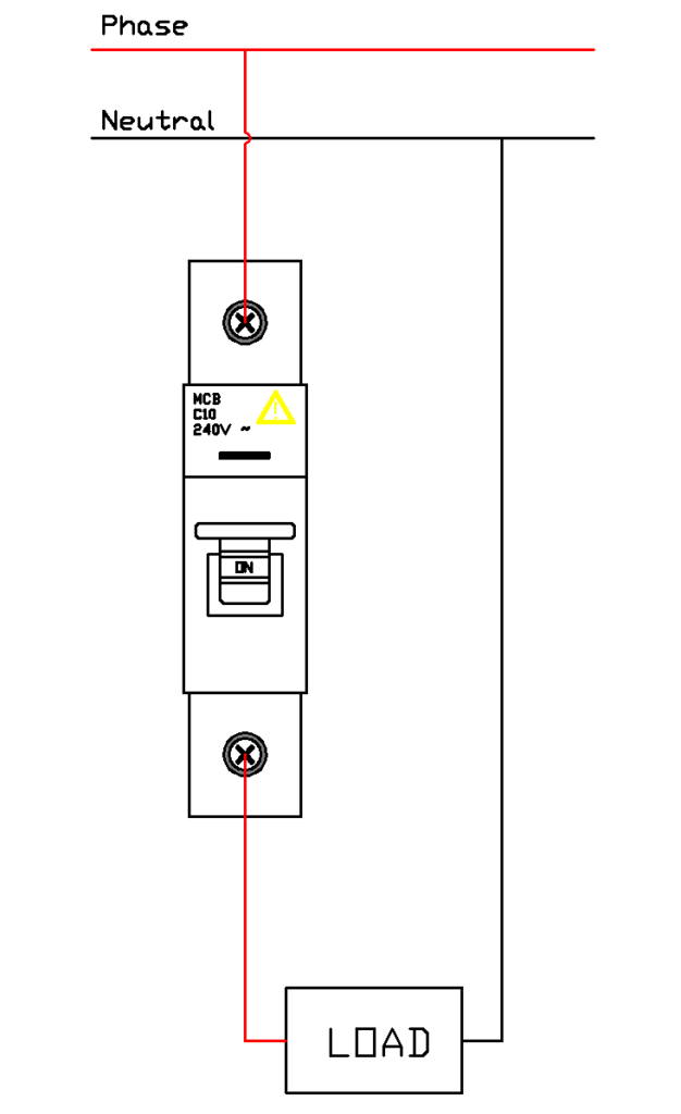
Single Pole Circuit Breaker Operation
Interactive Educational Animation
Control Panel
Status Display
4. Types of Circuit Breakers
Circuit breakers are classified based on various criteria including voltage level, arc-quenching medium, installation location, and operating mechanism.
4.1 Classification Based on Voltage Level
4.1.1 Low Voltage Circuit Breakers (Up to 1000V)
Low voltage circuit breakers are the most common type found in residential, commercial, and industrial applications. They protect circuits operating at voltages up to 1000V AC or 1500V DC.
Miniature Circuit Breakers, commonly known as MCBs, are the most common circuit breakers found in homes and small commercial buildings. They are designed for currents up to 125 amperes and are available in single-pole, double-pole, and triple-pole configurations. The circuit breakers in your home’s electrical panel that protect individual circuits for lighting, outlets, and appliances are typically MCBs rated at 15, 20, or 30 amperes.
Molded Case Circuit Breakers, or MCCBs, are larger than MCBs and can handle higher currents from 16 to 2500 amperes. They feature adjustable trip settings and are commonly used in industrial applications. For instance, a factory with large motors might use a 400-ampere MCCB to protect the main feeder circuit from the transformer to the main distribution panel.
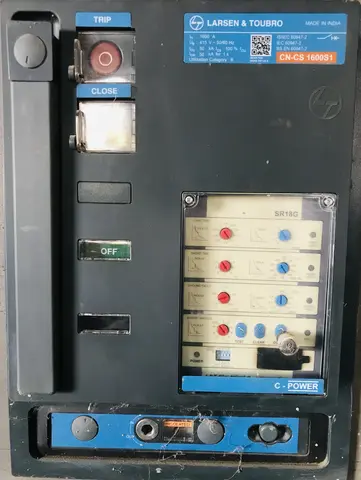
Air Circuit Breakers abbreviated as ACBs, are used for very high current applications typically ranging from 800 to 10,000 amperes. They use air as the arc-quenching medium and are commonly found in main distribution panels of large buildings and industrial facilities.

4.1.2 Medium Voltage Circuit Breakers (1kV to 52kV)
Medium voltage circuit breakers are used in power distribution systems, substations, and large industrial facilities. They protect circuits operating at voltages between 1,000 and 52,000 volts.
The main types include Vacuum Circuit Breakers (VCB), SF6 Circuit Breakers, and Oil Circuit Breakers.
4.1.3 High Voltage Circuit Breakers (52kV and Above)
High voltage circuit breakers are used in transmission systems and major substations. They handle voltages from 52kV up to 800kV or higher. These include SF6 Circuit Breakers, Dead Tank Circuit Breakers, and Live Tank Circuit Breakers.
The circuit breakers at a 400kV transmission substation that connects a power plant to the grid are high voltage SF6 circuit breakers capable of interrupting fault currents of 40,000 amperes or more.
4.2 Classification Based on Arc-Quenching Medium
4.2.1 Oil Circuit Breakers (OCB)
Oil circuit breakers use mineral oil as both an insulating and arc-quenching medium. When the contacts separate and an arc forms, the heat of the arc vaporizes the oil and creates hydrogen gas. This gas helps to cool and extinguish the arc.
There are two main types: Bulk Oil Circuit Breakers which use large tanks filled with oil where the contacts are immersed and Minimum Oil Circuit Breakers which use less oil with the arc interruption chamber containing only the essential amount.
Oil circuit breakers offer good arc-quenching properties and are suitable for high voltage applications with relatively simple construction. However, they present a fire hazard due to the flammable oil, require regular oil maintenance, and are large and heavy.
4.2.2 Air Circuit Breakers (ACB)
Air circuit breakers use air at atmospheric pressure as the arc-quenching medium. The arc is drawn out in arc chutes where it is lengthened, cooled, and extinguished. When the contacts separate, the arc is drawn into the arc chute which consists of a series of insulated metal plates called arc splitters. The arc is divided into multiple smaller arcs increasing the arc voltage and cooling the arc until it is extinguished.
These breakers offer the advantage of having no fire hazard, easy maintenance, and being environmentally friendly. They are also suitable for frequent operation. However, they are larger in size compared to other types, limited to low and medium voltage applications, and have slower arc extinction.
4.2.3 Vacuum Circuit Breakers (VCB)
Vacuum circuit breakers use a vacuum as the arc-quenching medium. The contacts are enclosed in a vacuum interrupter which is a sealed chamber with an extremely low pressure of about 10^-6 to 10^-8 torr. When the contacts separate in a vacuum an arc forms. However, the arc in a vacuum is quite different from an arc in air or oil. The metal vapor produced by the arc is quickly condensed on the metal shields inside the vacuum interrupter and the arc is extinguished at the first current zero crossing.
Vacuum circuit breakers offer excellent arc-quenching capability with very fast arc extinction. They have a compact size and long contact life of up to 30,000 operations. They are essentially maintenance-free and environmentally friendly. The main disadvantages are higher initial cost and limitation to medium voltage applications, typically up to 36kV. They also require specialized manufacturing.
Modern industrial facilities use vacuum circuit breakers for their 11kV and 33kV distribution systems because of their reliability and low maintenance requirements.
4.2.4 SF6 Circuit Breakers
SF6 circuit breakers use sulfur hexafluoride gas as the arc-quenching medium. SF6 is an excellent electrical insulator with arc-quenching properties approximately 100 times better than air. When the contacts separate an arc forms in the SF6 gas. The gas absorbs the energy from the arc breaking down into sulfur and fluorine ions. These ions quickly recombine as the current approaches zero, extinguishing the arc. The SF6 gas is then recirculated and reused.
These breakers offer excellent insulating and arc-quenching properties with a compact design. They are suitable for all voltage levels, have high reliability, and long service life. However, SF6 is a potent greenhouse gas that is 23,500 times more potent than CO2. The breakers also have high cost, require specialized handling and disposal, and present health hazards if decomposition products are released.
Most high voltage transmission substations at 132kV and above use SF6 circuit breakers because of their superior performance and compact size.
4.2.5 Air Blast Circuit Breakers
Air blast circuit breakers use a high-pressure air blast to extinguish the arc. Compressed air at pressures of 20-30 bar is released across the contacts when they separate. When the circuit breaker operates a blast of compressed air is directed at the arc rapidly cooling it and blowing away the ionized particles. This results in very fast arc extinction.
These breakers provide very fast arc extinction and are suitable for high-speed reclosing. They present no fire hazard and offer clean operation. However, they require a compressed air system, have high maintenance requirements, and are noisy in operation.
They are being replaced by SF6 and vacuum circuit breakers in many applications.
5. Components of a Circuit Breaker
5.1 Frame
The frame is the physical structure that houses all the circuit breaker components. It provides mechanical support and protection for the internal parts.
In molded case circuit breakers, the frame is made of insulating material usually thermoset plastic while in air circuit breakers, it is typically made of metal.
5.2 Contacts
Contacts are the conducting parts that make or break the electrical circuit. There are typically two types of contacts in a circuit breaker. Fixed contacts are stationary contacts mounted on the frame while moving contacts are the contacts that move to make or break the circuit.
Contacts are usually made of copper or copper alloys for good conductivity often plated with silver or silver alloys to reduce contact resistance and prevent oxidation.
5.3 Operating Mechanism
The operating mechanism is the mechanical system that opens and closes the contacts. Manual operation involves a handle or lever for manual opening and closing. The spring mechanism stores energy for rapid opening. Motor operation uses an electric motor for remote operation, while solenoid operation employs an electromagnetic device for automatic operation.
5.4 Trip Unit
The trip unit is the brain of the circuit breaker that senses fault conditions and initiates the tripping action. The thermal trip unit uses a bimetallic strip for overload protection. The magnetic trip unit uses an electromagnetic coil for short circuit protection. The thermal-magnetic trip unit combines both thermal and magnetic protection. The electronic trip unit uses electronic sensors and microprocessors for precise protection settings.
5.5 Arc Chute and Arc Extinction Chamber
The arc chute is designed to extinguish the arc that forms when the contacts separate under load. In air circuit breakers, it consists of a series of insulated metal plates called arc splitters that divide and cool the arc.
5.6 Trip Mechanism
The trip mechanism is the mechanical linkage that releases the operating mechanism when a fault is detected. It includes a trip bar, which is a rotating bar that releases the latch. The latch mechanism holds the contacts in the closed position. The trip-free mechanism ensures the breaker cannot be held closed during a fault.
5.7 Auxiliary Contacts
Auxiliary contacts are additional contacts that provide signals indicating the circuit breaker’s position whether open or closed. They are used for remote indication, interlocking with other equipment, and control circuit functions.
5.8 Arc Quenching Medium
Depending on the type of circuit breaker, the arc quenching medium may be air at atmospheric or compressed pressure, oil, vacuum, or SF6 gas.
6. Circuit Breaker Ratings and Specifications
6.1 Rated Current
The rated current also called the nominal current is the maximum continuous current the circuit breaker can carry without exceeding temperature limits. Common values for MCBs include 6A, 10A, 16A, 20A, 25A, 32A, 40A, 50A, and 63A.
For example, a 20-ampere circuit breaker can continuously carry 20 amperes without overheating or tripping.
6.2 Rated Voltage
The rated voltage is the maximum voltage at which the circuit breaker is designed to operate. This includes both the maximum continuous operating voltage and the rated insulation voltage.
A circuit breaker rated at 230V AC is designed for single-phase household circuits, while a 400V AC rating is for three-phase industrial applications.
6.3 Breaking Capacity
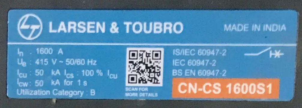
The breaking capacity is the maximum fault current that the circuit breaker can safely interrupt. It is expressed in kiloamperes (kA). The Ultimate Breaking Capacity (designated as \(I_{cu}\)) is the maximum current the breaker can interrupt after which it may not be suitable for further service. The Service Breaking Capacity (designated as \(I_{cs}\)) is the current the breaker can interrupt multiple times without damage.
For example, a circuit breaker with a breaking capacity of 10kA can safely interrupt a fault current of up to 10,000 amperes.
6.4 Trip Characteristics
Trip characteristics define how the circuit breaker responds to overcurrents. Common trip curves for MCBs include Type B which trips between 3-5 times rated current and is suitable for resistive loads. Type C trips between 5-10 times rated current and is appropriate for moderate inductive loads. Type D trips between 10-20 times rated current and is designed for highly inductive loads.
For example, a Type B circuit breaker rated at 16A will trip instantaneously if the current exceeds 48-80 amperes. This is suitable for residential lighting circuits. A Type D circuit breaker is better suited for motor circuits where high inrush currents occur during starting.
6.5 Number of Poles
Circuit breakers are available in various pole configurations. Single-pole breakers protect one phase conductor. Double-pole breakers protect two conductors simultaneously. Triple-pole breakers protect three phase conductors. Four-pole breakers protect three phases plus neutral.
A single-phase 230V household circuit uses single-pole or double-pole circuit breakers, while a three-phase 400V industrial motor circuit uses triple-pole circuit breakers.
6.6 Making Capacity
The making capacity is the maximum current that the circuit breaker can close onto during a short circuit. It is typically higher than the breaking capacity because closing onto a fault is more demanding than interrupting a fault.
The making capacity (designated as \(I_{cm}\)) is usually 2.2 times \(I_{cu}\) for AC circuits.
7. Applications of Circuit Breakers
Circuit breakers are used in virtually every electrical system. Their applications span from residential homes to power generation stations.
7.1 Residential Applications
In homes, circuit breakers protect individual circuits and provide a main disconnect. The main breaker usually rated at 100-200A provides overall protection and serves as the main disconnect.
Branch circuit breakers rated at 15-30A MCBs protect individual circuits for lighting, outlets, and small appliances. Dedicated circuit breakers with higher amperage ratings protect specific appliances like water heaters, air conditioners, and electric ranges.
GFCI breakers provide Ground Fault Circuit Interrupter protection for wet locations like bathrooms and kitchens. AFCI breakers provide Arc Fault Circuit Interrupter protection for bedrooms and living areas.
A typical home might have a 200A main breaker panel with 20-40 individual MCBs protecting various circuits throughout the house.
7.2 Commercial Applications
Commercial buildings have more complex electrical systems requiring various types of circuit breakers. Main distribution panels use air circuit breakers or large MCCBs. Sub-distribution panels utilize MCCBs and MCBs. Motor control centers employ MCCBs with motor protection features. UPS systems have breakers protecting uninterruptible power supplies. Emergency power systems include breakers for generator and transfer switch circuits.
A shopping mall might have a 4000A air circuit breaker as the main breaker with multiple MCCB-protected feeders supplying different areas of the building.
7.3 Industrial Applications
Industrial facilities use circuit breakers for protection in demanding environments. Motor protection requires MCCBs and dedicated motor circuit protectors. Power distribution uses ACBs and MCCBs in main and sub-distribution panels. Process equipment requires circuit breakers with specialized trip characteristics. Hazardous areas need explosion-proof circuit breakers.
7.4 Power Generation and Transmission
Power plants and transmission systems use high-voltage circuit breakers. Generator protection requires high-voltage breakers at generator terminals. Transmission lines use SF6 or oil circuit breakers at transmission voltages. Substation protection involves multiple circuit breakers for various protection zones. Bus tie breakers connect and disconnect sections of bus bars.
7.5 Power Distribution Substations
Distribution substations use medium-voltage circuit breakers. Incoming feeders have breakers on lines from the transmission system. Outgoing feeders have breakers on distribution lines to customers. Capacitor bank switching uses breakers for reactive power control. Transformer protection requires breakers on primary and secondary sides.
7.6 Renewable Energy Systems
Modern renewable energy systems extensively use circuit breakers. Solar PV systems require DC and AC circuit breakers. Wind turbines use medium-voltage breakers for grid connection. Energy storage systems need DC breakers for battery protection. Grid interconnection requires breakers at the point of common coupling.
8. Circuit Breaker Selection Criteria
Selecting the correct circuit breaker for a specific application involves considering multiple factors to ensure safe and reliable operation.
8.1 Voltage Rating
The circuit breaker must be rated for the system voltage. Select a breaker with a rated voltage equal to or higher than the maximum system voltage. For a 400V three-phase system, select a circuit breaker rated for at least 400V AC.
8.2 Current Rating
The circuit breaker current rating should be higher than the maximum continuous load current, lower than the current-carrying capacity of the protected conductors, and coordinated with upstream and downstream protective devices.
For a circuit with 30A continuous load and 40A rated conductors, select a 32A or 40A circuit breaker.
8.3 Breaking Capacity
The breaking capacity must exceed the maximum prospective fault current at the installation point. This requires a fault current study of the electrical system.
If the calculated maximum fault current at a distribution panel is 15kA, select circuit breakers with a breaking capacity of at least 15kA or higher.
8.4 Trip Characteristics
Select the appropriate trip curve based on the load characteristics. Type B is suitable for resistive loads such as lighting and heating. Type C works well for moderate inductive loads including general purpose applications and small motors. Type D is designed for highly inductive loads like large motors and transformers.
9. Installation of Circuit Breakers
9.1 Mounting Position
Most circuit breakers are designed to be mounted vertically with the “ON” position at the top. Check manufacturer specifications for approved mounting positions as some breakers may be derated or prohibited from horizontal mounting.
9.2 Enclosure Selection
Circuit breakers should be installed in appropriate enclosures based on the environment. NEMA 1 enclosures are for indoor, general purpose use. NEMA 3R enclosures are for outdoor, rain-tight applications. NEMA 4X enclosures are for washdown and corrosion-resistant requirements. NEMA 7 enclosures are for hazardous locations requiring explosion-proof protection.
9.3 Conductor Sizing and Termination
Ensure proper conductor sizing and use approved termination methods. Follow manufacturer torque specifications for terminal screws and use properly sized wire connectors. Maintain appropriate wire bending space and separate line and load conductors.
9.4 Labeling and Identification
Properly label circuit breakers to identify the circuit served, rated current, trip curve type, and phase identification for three-phase systems.
9.5 Testing After Installation
After installation, test circuit breakers to verify proper operation. This includes verifying mechanical operation by opening and closing the breaker, testing the trip function if possible and checking auxiliary contacts.
10. Maintenance of Circuit Breakers
10.1 Preventive Maintenance Activities
Visual inspection should check for signs of overheating such as discoloration or melting, inspect for physical damage, verify proper mounting, check for contamination from dust or moisture, and inspect terminals for corrosion.
Operational testing involves manually operating the breaker by opening and closing it, verifying smooth operation, checking position indicators, and testing auxiliary contacts.
Electrical testing includes measuring contact resistance, testing insulation resistance, verifying trip unit operation, and checking current transformer ratios if applicable.
Mechanical maintenance involves lubricating moving parts as specified by the manufacturer, checking the spring charging mechanism, inspecting arc chutes for damage, and verifying latching mechanism operation.
10.2 Maintenance Intervals
Maintenance frequency depends on several factors including circuit breaker type, operating environment, number of operations, and criticality of the protected circuit.
- MCBs should be inspected annually and replaced every 15-25 years.
- MCCBs should be inspected every 1-3 years with maintenance every 5 years.
- ACBs should be inspected every 6-12 months with maintenance every 2-3 years.
- Medium and high voltage breakers should be inspected every 6 months with annual maintenance.
10.3 Safety Precautions During Maintenance
Always de-energize and lock out/tag out before maintenance. Follow manufacturer procedures and use appropriate personal protective equipment (PPE). Verify absence of voltage before working and be aware of stored energy in springs and capacitors.
11. Testing of Circuit Breakers
Primary injection testing involves injecting actual current through the primary circuit. This tests the complete protective chain and verifies coordination with other devices.
Secondary injection testing involves injecting test signals directly into the trip unit. This is faster and simpler than primary injection and is useful for electronic trip units.
Insulation resistance testing measures resistance between phases and ground to identify insulation degradation. This is typically performed at 500V or 1000V DC.
Contact resistance testing measures resistance across closed contacts. High resistance indicates worn or contaminated contacts. This is typically measured at 100A DC or higher.
Timing tests measure opening and closing times to verify mechanical condition and identify worn parts or lubrication issues.
12. Safety Standards and Regulations
Circuit breakers must comply with various standards and regulations to ensure safety and reliability.
12.1 International Standards
The IEC 60947 Series covers low-voltage switchgear and controlgear. IEC 60947-1 provides general rules, IEC 60947-2 covers circuit breakers, and IEC 60947-3 addresses switches, disconnectors, and switch-disconnectors.
The IEC 62271 Series covers high-voltage switchgear and controlgear. IEC 62271-1 provides common specifications, IEC 62271-100 covers AC circuit breakers, and IEC 62271-200 addresses AC metal-enclosed switchgear.
12.2 North American Standards
UL Standards include UL 489 for molded-case circuit breakers, molded-case switches, and circuit-breaker enclosures. UL 1066 covers low-voltage AC and DC power circuit breakers used in enclosures. UL 1077 addresses supplementary protectors for use in electrical equipment.
NEMA Standards include NEMA AB 1, which covers molded case circuit breakers, molded case switches, and circuit-breaker enclosures.
IEEE Standards include the IEEE C37 Series for switchgear standards and IEEE 1015 for applying low-voltage circuit breakers used in industrial and commercial power systems.
12.3 Installation Codes
The National Electrical Code, also known as NEC or NFPA 70, provides requirements for circuit breaker application and installation in the United States. IEC 60364 is the international standard for electrical installations in buildings.
13. Circuit Breakers vs. Fuses
While both circuit breakers and fuses provide overcurrent protection, they have distinct differences that make each suitable for specific applications.
| Feature | Circuit Breaker | Fuse |
|---|---|---|
| Reusability | Can be reset and reused | One-time use, must be replaced |
| Initial Cost | Higher | Lower |
| Operating Cost | Lower (no replacement) | Higher (replacement required) |
| Breaking Capacity | Generally lower | Generally higher |
| Speed | Slower | Faster (for current-limiting fuses) |
| Selectivity | Easier to coordinate | Excellent inherent selectivity |
| Maintenance | Requires periodic testing | Minimal maintenance |
| Remote Operation | Possible | Not possible |
| Safety | Safer (no exposed elements) | Risk of incorrect replacement |
Fuses are preferred where high breaking capacity is required, where fast current-limiting is needed, for protection of equipment with precise protection requirements, and in applications where simplicity is preferred.

Circuit breakers are preferred where frequent switching is required, where remote operation is needed, where reusability reduces costs, and in residential applications for safety.
14. Conclusion
Circuit breakers are fundamental protective devices in electrical systems serving as the first line of defense against electrical hazards. From the simple MCB protecting a household circuit to advanced SF6 breakers protecting high-voltage transmission lines, circuit breakers play an important role in electrical safety and reliability.
For electrical engineering students, developing a thorough understanding of circuit breakers provides a strong foundation for a career in the electrical industry. The principles discussed in this guide, from basic operation to advanced applications, will serve as valuable knowledge throughout your professional journey.
15. Frequently Asked Questions (FAQs)
Residential MCBs typically last 25-30 years if not subjected to repeated trips or harsh conditions. Industrial circuit breakers should be evaluated during regular maintenance and replaced if they fail testing or show signs of wear.
Common causes include overloaded circuits, short circuits, ground faults, faulty appliances, loose connections, or a defective circuit breaker. Investigate the cause before repeatedly resetting.
In many jurisdictions, replacing a circuit breaker requires a licensed electrician. Even where DIY work is permitted, it involves significant electrical hazards and should only be attempted by those with proper training and equipment.
MCBs (Miniature Circuit Breakers) are designed for lower currents up to 125A and have fixed trip settings. MCCBs (Molded Case Circuit Breakers) handle higher currents up to 2500A or more and often have adjustable trip settings.
If a breaker won’t reset, the fault may still be present. Disconnect all loads from the circuit and try again. If it still won’t reset, the breaker may be defective and require replacement.