In electrical substations, uninterrupted power supply to essential control and protection circuits is important for safe and reliable power system operation. The DC changeover relay is a vital component that provides automatic switching between two independent DC power sources without interrupting the supply to essential circuits and loads. This device acts as an intelligent switch that monitors the health of the primary DC source and seamlessly switches to a backup source when the primary source fails.
In this technical guide we will discuss How DC Changeover Relays Work, their Construction, Operating Principles, Circuit Diagram of a typical DC Changeover Scheme and practical applications in modern substations with examples.
1. What is a DC Changeover Relay?
A DC changeover relay is an electromechanical device that automatically switches the power supply between two DC sources based on the availability and health of those sources. It consists of a relay coil and multiple contact sets that control the distribution of power to various substation circuits and equipment.
The primary function of a DC changeover relay is to ensure continuous power delivery to essential substation circuits such as Circuit Breaker Closing and Tripping Mechanisms, Differential Protection Relays, Overcurrent and Earth Fault Protection Relays, Distance Protection Relays Annunciation Circuits, Emergency Lighting, etc. When the primary DC source (DC-1) fails or becomes unavailable, the relay automatically transfers the load to the secondary DC source (DC-2) without any manual intervention or delay.
1.1 Key Components of a DC Changeover Relay Circuit
- Relay Coil
- NO Contacts (Normally Open)
- NC Contacts (Normally Closed)
- Fuses
- Control and Load Circuits
2. Circuit Diagram and Component Layout of DC Changeover Relay
Consider the following diagram for a typical DC changeover relay circuit. As shown in the circuit diagram, the DC changeover relay circuit consists of two DC sources (DC-1 and DC-2), each with individual 32A fuses for protection. The relay coil receives power directly from the primary source (DC-1), while the contacts are arranged to distribute power to four important substation circuits:
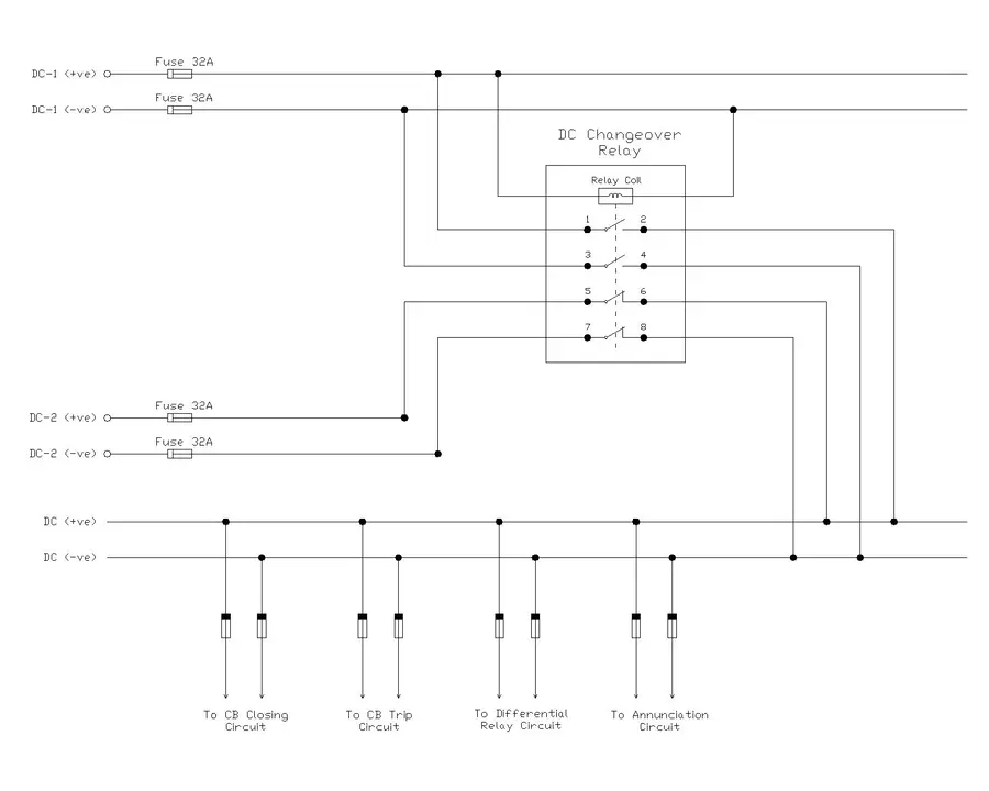
- CB Closing Circuit: Supplies power to the mechanism that closes the circuit breaker
- CB Tripping Circuit: Supplies power to the mechanism that opens the circuit breaker during faults
- Differential Relay Circuit: Powers the differential protection relay that detects internal transformer faults
- Annunciation Circuit: Supplies power to alarm and indication systems
3. Operating Principles of DC Changeover Relay
3.1 Scenario 1: When Both DC Sources Are Available
When both the primary source (DC-1) and the backup source (DC-2) are operational and providing voltage, the DC changeover relay operates in its normal mode. The primary DC source directly energizes the relay coil, pulling the relay armature inward and changing the contact configuration.
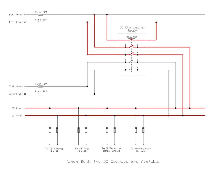
In this state:
- The NO (Normally Open) contacts 1-2 and 3-4 transition to a closed state
- The NC (Normally Closed) contacts 5-6 and 7-8 transition to an open state
- Power flows through the newly closed contacts 1-2 and 3-4 directly from the primary DC source (DC-1) to supply all four load circuits
- The secondary DC source (DC-2) remains in standby mode and does not carry any load current
This is the preferred operating condition because the primary source powers all circuits. The relay maintains this configuration as long as DC-1 remains energized and above the minimum operating voltage threshold.
3.2 Scenario 2: When Only DC-1 Source Is Available
If the secondary DC source (DC-2) fails, becomes disconnected, or drops below its minimum operating voltage, the relay continues to operate normally because it is already being supplied by DC-1. This scenario is identical to Scenario 1 in terms of relay operation. However, when DC-2 fails, the DC Supply Supervision Relay associated with the DC-2 source will initiate an alarm which alerts the operator.
The relay remains energized by DC-1, the NO contacts stay closed, and the NC contacts remain open. All loads continue to receive power from the primary source through the closed NO contacts. The relay automatically maintains the supply without requiring any adjustment or manual intervention because the relay detects only the status of DC-1, on which its coil depends.
3.3 Scenario 3: When DC-1 Fails and DC-2 is Available
This scenario represents the situation that demonstrates the value of the changeover relay. When the primary DC source (DC-1) fails, drops below the relay’s operating voltage, or is disconnected for maintenance, the relay coil loses its energization current.
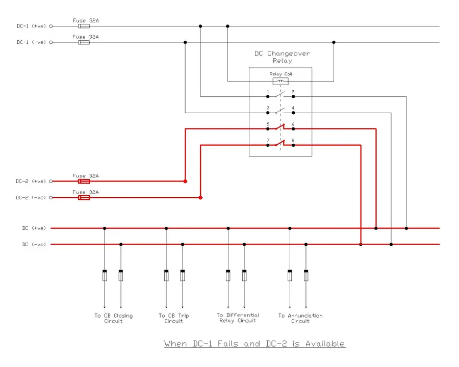
When the relay coil de-energizes:
- The relay armature returns to its default (spring-loaded) position
- The NO contacts 1-2 and 3-4 open (returning to their normally open state)
- The NC contacts 5-6 and 7-8 close (returning to their normally closed state)
- Power automatically transfers to the backup DC source (DC-2)
- All four load circuits receive power through the now-closed NC contacts 5-6 and 7-8 from the secondary source
- The transfer happens within milliseconds, ensuring no interruption to the load circuits
This automatic switchover is the main advantage of the DC changeover relay. Without this relay, an operator would need to manually switch the supply after a delay.
4. Practical Example: Substation Scenario
Consider a 220 kV transmission substation equipped with modern protection relays and automated control systems. This substation relies on DC supply for:
- Operating the spring-charged mechanism that closes the main circuit breaker (required during load pickup)
- Triggering the trip coil to open the circuit breaker during fault conditions
- Powering sensitive differential relays that protect the power transformer
- Running alarm indicators and communication devices
The substation has two independent DC sources:
- DC-1 (Primary)
- DC-2 (Backup)
During normal operation, DC-1 supplies all circuits through the closed NO contacts. If a rectifier failure or battery degradation causes DC-1 voltage to drop, the DC changeover relay immediately detects this condition (through its de-energization), and all circuits switch to DC-2 within a few milliseconds.
5. Advantages of DC Changeover Relay
The DC changeover relay provides several important benefits that make it indispensable in modern substations:
- Automatic Redundancy: The relay eliminates the need for manual source switching.
- Minimal Response Time: The electromagnetic switching occurs within milliseconds, ensuring that circuits remain powered during transient source failures.
- Simple and Reliable Design: The relay contains no complex electronics or microprocessors. Its mechanical design has been proven over decades of operation in harsh substation environments.
- Cost-Effective Solution: Compared to advanced dual-source power supplies or UPS systems, the DC changeover relay is a low-cost method to achieve redundant power delivery.
- Maintenance-Free Operation: Once properly installed and tested, the relay requires minimal maintenance and has a long operational life.
- Protection Compatibility: The relay integrates seamlessly with existing protection schemes, fuses, and control circuits without requiring modifications to other equipment.
6. Installation and Wiring
When installing a DC changeover relay in a substation, several important factors must be considered to ensure safe and reliable operation:
- Fuse Sizing: Each DC source must have a main fuse (typically 32A) rated to protect the source wiring and prevent excessive current flow during short circuits. Additional branch fuses protect individual load circuits (CB closing, CB tripping, etc.)
- Cable Selection: Control cables must be sized to handle the maximum operating current without exceeding temperature limits.
- Voltage Compatibility: Both DC sources must provide the same nominal voltage (commonly 110V DC or 220V DC) to prevent damage to connected loads
- Grounding: Proper grounding of both DC sources and control circuits is essential for safety and reliable relay operation
- Testing: After installation, the relay must be tested with both sources available and then individually to ensure the automatic switchover function works correctly
6.1 DC Changeover Relay Wiring Schedule
For the above circuit diagram, the wiring schedule is tabulated below:
| S.No. | Wire No. | From | To | Purpose |
|---|---|---|---|---|
| 1 | DC1P/FS1 | DC-1 (+ve) Terminal | Fuse 32A | DC-1 Positive Supply |
| 2 | DC1N/FS2 | DC-1 (-ve) Terminal | Fuse 32A | DC-1 Negative Supply |
| 3 | DC2P/FS3 | DC-2 (+ve) Terminal | Fuse 32A | DC-2 Positive Supply |
| 4 | DC2N/FS4 | DC-2 (-ve) Terminal | Fuse 32A | DC-2 Negative Supply |
| 5 | FS1/DCCO-P | Fuse-DC1-P Output | Relay Coil (+) Terminal | DC Changeover Relay Coil Positive Supply |
| 6 | FS1/DCCO-N | Fuse-DC1-N Output | Relay Coil (-) Terminal | DC Changeover Relay Coil Negative Supply |
| 7 | FS1/NO-1 | Fuse-DC1-P Output | Relay NO Contact Terminal No. 1 | DC 1 Positive Supply to NO Contact |
| 8 | FS2/NO-3 | Fuse-DC1-N Output | Relay NO Contact Terminal No. 3 | DC 1 Negative Supply to NO Contact |
| 9 | NO-2/DCB-P | Relay NO Contact Terminal No. 2 | DC (+ve) Common Bus | DC 1 Load (Positive) |
| 10 | NO-4/DCB-N | Relay NO Contact Terminal No. 4 | DC (-ve) Common Bus | DC 1 Load (Positive) |
| 11 | FS3/NC-5 | Fuse-DC2-P Output | Relay NC Contact Terminal No. 5 | DC 2 Positive Supply to NC Contact |
| 12 | FS4/NC-7 | Fuse-DC2-N Output | Relay NC Contact Terminal No. 7 | DC 2 Negative Supply to NC Contact |
| 13 | NC-6/DCB-P | Relay NC Contact Terminal No. 6 | DC (+ve) Common Bus | DC 2 Load (Positive) |
| 14 | NC-8/DCB-N | Relay NC Contact Terminal No. 8 | DC (-ve) Common Bus | DC 2 Load (Positive) |
7. Conclusion
The DC changeover relay is an essential component in electrical substations that ensures automatic switching between two independent DC power sources. Understanding its construction, operating principles, circuit diagram, practical applications, etc. are important for electrical engineers and technicians for maintaining reliable DC supply systems in substation operation and protection.
The relay’s ability to provide automatic switchover without manual intervention makes it an essential device. Whether in traditional mechanical substations or advanced digital substations, the DC changeover relay continues to play a vital role in ensuring that protection, control, and communication circuits remain powered under all operating conditions.
8. Frequently Asked Questions
A: No, the DC changeover relay ensures that only one source supplies the load at any time. This prevents the sources from paralleling and causing circulating currents or damage.
A: If both sources fail simultaneously, all control circuits lose power. This is a rare event, but if circuits require power even during dual-source failure, an uninterruptible power supply (UPS) would be required.
A: The automatic switchover typically occurs within 50-100 milliseconds, which is fast enough to prevent interruption of control functions.
A: Yes, the relay can be tested by reducing the voltage of DC-1 to observe the switchover to DC-2, then restoring DC-1. This confirms proper operation without requiring shutdown of the substation.
A: With proper maintenance and operation within rated conditions, a relay can function reliably for 20-30 years or longer.