In electrical substations, the DC supply system forms the backbone of protection and control operations. A DC Supervision Relay plays an important role in monitoring this DC power source and ensures that control panels, protection relays, circuit breakers, etc receive uninterrupted DC power. Without proper supervision of the DC system, a substation could face catastrophic failures during fault conditions when protection systems are needed most.
In this technical guide we will discuss what is a DC Supervision Relay, how DC Supervision Relays work, Circuit Diagram of a DC Supervision Relay Circuit, their importance in substations, and practical applications.
1. What is a DC Supervision Relay?
A DC Supervision Relay is a protective device that continuously monitors the health and voltage level of the DC power supply in control and relay panels. Think of it as a watchdog that keeps an eye on your substation’s DC battery system.
When the DC voltage drops below or rises above predetermined limits, or when there’s a complete loss of DC supply, the relay immediately triggers an alarm to alert operators.
2. How DC Supervision Relay Works in Substations
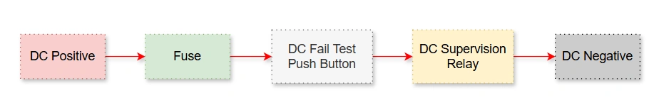
The DC Supervision Relay connects directly to the main DC incoming source of a Control and Relay Panel. The connection path includes the main DC fuses and a normally closed contact from a DC Fail test push button.
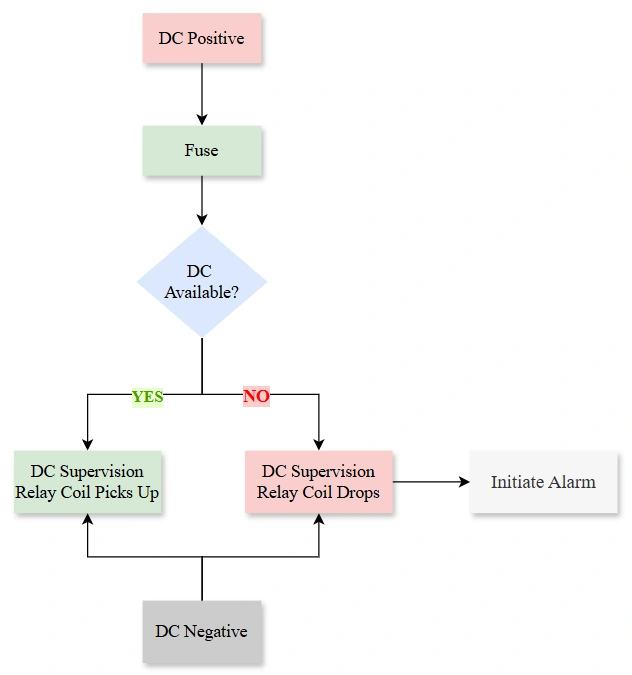
When the DC supply is healthy and the test push button remains unpressed, the circuit completes through the DC Supervision Relay coil. The normally closed contact of the test push button stays in its default state, allowing current to flow uninterrupted.
3. The DC Supervision Relay Circuit
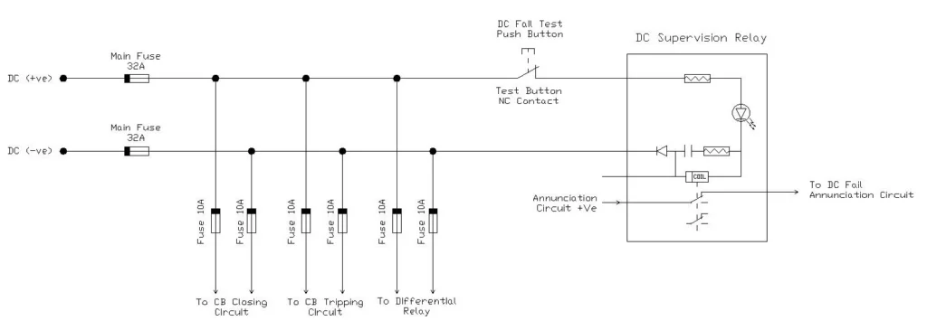
The example circuit diagram illustrates a typical DC supervision system used in substations. Let me explain each component and how they work together to provide reliable monitoring of the DC system.
3.1 Main DC Supply and Fuse Protection
The circuit begins with the main DC supply, which provides both positive (+ve) and negative (-ve) rails. The positive rail passes through a Main Fuse rated at 32A before distributing power to various circuits. This main fuse protects the entire DC distribution system from overcurrent conditions. Similarly, the negative rail also includes a 32A Main Fuse to complete the protective scheme.
3.2 Distribution to Multiple Circuits
From the main DC rails, the power distributes to several circuits through individual branch fuses rated at 10A each. These branch circuits typically supply:
- Circuit Breaker (CB) Closing Circuit: This circuit provides the DC power necessary to energize the closing coil of circuit breakers.
- Circuit Breaker (CB) Tripping Circuit: This circuit provides the DC power necessary to energize the Tripping coil of circuit breakers.
- Differential Relay: The differential protection relay receives its control power from this branch.
Each of these branch circuits includes its own 10A fuse, providing selective coordination. If a fault occurs in one branch, only that specific fuse will blow, leaving other circuits operational.
3.3 The DC Fail Test Push Button Circuit
As shown in the circuit, the DC Fail Test Push Button with its normally closed (NC) contact positioned in series with the positive supply to the DC Supervision Relay. During normal operation, this NC contact remains closed, allowing current to flow to the supervision relay.
When maintenance personnel or operators want to test the DC supervision system, they press the test push button. This action opens the NC contact, interrupting the DC supply to the supervision relay. The relay then behaves exactly as it would during an actual DC failure and provides a realistic test of the entire alarm chain without needing to actually disconnect the main DC supply.
This test is essential for verifying that the supervision system will function correctly when a real DC failure occurs. The test can be performed safely during routine maintenance without disrupting substation operations.
3.4 DC Supervision Relay Internal Components
Inside the DC Supervision Relay box, several components work together:
- Relay Coil: The heart of the supervision system is the relay coil, which energizes when adequate DC voltage is present. The coil is designed to operate with minimal current consumption, typically drawing only 5-50 milliamperes.
- Series Resistances: Multiple resistors appear in series with the relay coil. These resistances serve two purposes: they limit the supervision current to a safe, minimal level, and they help create the voltage drop needed for proper relay operation. The resistor network ensures that the relay coil receives just enough current to remain picked up during healthy DC conditions.
- Diode: A diode connected across the relay coil provides protection against voltage spikes that occur when the relay coil de-energizes.
- RC Circuit for Time Delay: A resistor-capacitor combination creates the time delay function. When the DC voltage drops, the capacitor discharges through the resistor, delaying the relay’s response. This prevents false alarms from momentary voltage dips or switching transients.
- Auxiliary Contacts: The relay includes auxiliary contacts that change state when the coil energizes or de-energizes. These contacts interface with the annunciation circuit.
3.5 Annunciation Circuit Connection
The relay’s normally closed auxiliary contact connects to the of the Annunciation Circuit. During normal operation when the DC supply is healthy, the relay coil is energized and this NC contact opens. With the contact open, the annunciation circuit remains inactive and no alarm sounds.
When the DC voltage falls outside acceptable limits or fails completely, the relay coil de-energizes. The auxiliary contacts return to their normal state, closing the NC contact. This completes the annunciation circuit, triggering the DC Fail alarm in the control room.
3.6 Current Flow During Normal Operation
Under healthy DC conditions, current flows from the positive DC rail through the main fuse, past the closed NC contact of the test push button, and into the DC Supervision Relay. Inside the relay, current passes through the series resistances and the relay coil before returning to the negative DC rail through the second main fuse.
This continuous current flow, though minimal in magnitude, keeps the relay coil energized and its contacts in the operated position.
3.7 Circuit Behavior During DC Failure
When the DC supply voltage drops below the relay’s lower threshold setting (for example, below 85V in a nominal 110V system), insufficient current flows through the relay coil. The magnetic field in the coil weakens and can no longer hold the armature in the picked-up position. The relay drops out, its contacts return to their normal state, and the alarm circuit activates.
Similarly, if the DC voltage rises excessively high (for example, above 140V due to charger malfunction), the relay may also drop out depending on its design and settings.
4. Testing the DC Supervision Function
Every protection system requires periodic testing to verify its operational readiness, and the DC Supervision Relay is no exception. The relay includes a dedicated test function accessed through the DC Fail Test Push Button integrated into the circuit.
4.1 Test Procedure
When an operator presses the DC Fail Test Push Button, its normally closed contact opens, interrupting the positive DC supply to the supervision relay. This simulates a DC supply failure condition. The relay coil de-energizes, contacts change state, and the alarm system activates—just as it would during a real DC failure.
Regular testing, usually performed during routine maintenance schedules, ensures that the supervision system will reliably detect actual DC failures when they occur. Most substations include this test in their monthly or quarterly preventive maintenance procedures.
4.2 Relationship with Trip Circuit Supervision
The DC Supervision Relay shares significant similarities with the Trip Circuit Supervision Relay, another protective device in substations. In fact, many substations use the same relay model for both functions, simply configuring the settings differently.
While the DC Supervision Relay monitors the overall DC supply to control panels, the Trip Circuit Supervision Relay monitors the specific circuit that provides tripping power to circuit breakers. Both relays operate on the same principle of drawing a small supervision current and detecting when that current falls outside acceptable limits.
5. Common Relays Used for DC Supervision
5.1 ABB TSR Relay
The ABB TSR (Trip and Supervision Relay) is widely used in substations worldwide for both DC supervision and trip circuit supervision applications. This relay offers several key features:
- Voltage Range: Typically available for 24V, 48V, 110V, and 220V DC systems
- Supervision Current: Adjustable, usually 5-50 mA depending on model
- Time Delay: Adjustable from 0 to several seconds
- Contact Configuration: Multiple auxiliary contacts for alarm and indication circuits
- Mounting: Panel mount or DIN rail mount options
The TSR relay provides reliable supervision with minimal maintenance requirements, making it a popular choice for substation applications.
5.2 Schneider Electric Supervision Relays
Schneider Electric offers the Zelio Control line of supervision relays suitable for DC monitoring applications. These devices provide voltage monitoring with adjustable upper and lower limits, time delay functions, and multiple output contacts for complex alarm schemes.
5.3 Siemens 7PA Supervision Relay
Siemens manufactures supervision relays under their 7PA series, designed specifically for DC supervision and trip circuit monitoring. These relays feature digital setting capabilities, LED indication, and self-monitoring functions that enhance reliability.
6. Practical Applications in Substations
6.1 Battery System Monitoring
In substations, DC Supervision Relays continuously monitor the battery banks that provide backup power during AC power failures. If the battery charger fails or batteries deteriorate over time, the supervision relay detects the voltage deviation and alerts maintenance personnel before the situation becomes critical.
For instance, in a remote substation with a 110V battery system, the DC Supervision Relay might detect that the float voltage has dropped from the normal 125V to 105V over several months due to aging batteries. This early warning allows utilities to schedule battery replacement during planned outages rather than experiencing unexpected failures.
6.2 Control Panel Supply Monitoring
Each control panel in a substation typically includes its own DC Supervision Relay to monitor the DC supply feeding that specific panel. This localized monitoring helps maintenance teams quickly identify which panel or section of the substation has lost DC power during troubleshooting.
6.3 Redundant System Supervision
Many substations uses redundant DC systems with automatic transfer between primary and backup supplies. DC Supervision Relays monitor both sources, providing alarms if either system fails and ensuring that operators know the redundancy status at all times.
7. Benefits of DC Supervision in Substations
The implementation of DC Supervision Relays provides multiple operational and safety benefits. These devices offer early warning of DC system problems. This allows corrective action before protection systems are compromised. They reduce the risk of protection system failures during actual fault conditions when reliable DC power is most needed.
From a maintenance perspective, supervision relays help utilities optimize their maintenance schedules by providing advance notice of battery degradation or charger problems. This predictive capability transforms maintenance from reactive to proactive.
The continuous monitoring aspect means that problems are detected immediately, 24 hours a day, without requiring manual voltage measurements. This automatic surveillance significantly enhances substation safety and reliability compared to periodic manual checks alone.
8. Installation and Configuration Best Practices
When installing DC Supervision Relays in substations, several practices to be followed as detailed below ensure optimal performance:
- Proper Voltage Range Selection: Choose relays rated for the specific DC system voltage in your substation. Using a 110V relay on a 48V system or vice versa will result in incorrect operation.
- Appropriate Time Delay Settings: Configure time delays long enough to avoid nuisance alarms from transient disturbances but short enough to provide timely warning of genuine problems. A setting of 1-3 seconds typically works well for most applications.
- Series Resistance Calculation: Ensure that series resistances are correctly sized to limit the supervision current to the designed level. Excessive current wastes battery capacity, while insufficient current may cause unreliable operation.
- Regular Testing: Establish a routine testing schedule using the DC Fail Test function. Monthly testing is common practice in substations.
- Alarm Circuit Verification: Ensure that alarm circuits are properly connected and that alarms annunciate in manned control rooms or are transmitted to SCADA systems for remote monitoring.
9. Troubleshooting Common Issues
9.1 False Alarms
If a DC Supervision Relay triggers frequent false alarms, check for loose connections, insufficient time delay settings, or voltage fluctuations from nearby equipment switching. Tightening connections and adjusting the time delay usually resolves these issues.
9.2 Relay Fails to Alarm During Testing
When the test push button doesn’t trigger an alarm, verify that the push button contacts are functioning, check for broken wires in the alarm circuit, and confirm that the relay itself hasn’t failed. Use a multimeter to trace the circuit and identify the problem point.
9.3 Incorrect Voltage Threshold Operation
If the relay operates at the wrong voltage levels, verify the relay settings match the intended thresholds. Some relays use DIP switches or potentiometers for adjustment, while modern digital relays require software configuration.
10. Practical Examples of DC Supervision Relay Application
10.1 Example 1: High Voltage Transmission Substation
In a 220 kV transmission substation, the DC Supervision Relay continuously monitors the 110V DC system that powers the distance protection relays, trip coils, and control circuits. When the main DC charger fails suddenly during a summer afternoon, the DC voltage begins to drop gradually as the battery discharges under the continuous load of the protection and control systems.
When the voltage drops to 95V (below the alarm set point of 100V), the DC Supervision Relay coil loses pickup and the alarm is triggered. The substation operator, alerted by the audible and visual alarm on the control panel, immediately switches the DC supply to the standby charger. Within minutes, the DC system is restored to 110V, and the alarm is cleared automatically as the relay re-energizes. This quick response prevented any risk of protection system failure that could have caused a cascading power system blackout.
10.2 Example 2: Distribution Substation with Battery Backup
A 33 kV distribution substation operates with a 48V DC system powered by a charger and backed up by a battery string. During routine scheduled maintenance, a technician inadvertently damages one of the battery cable connectors, creating a high-resistance connection. This causes the DC voltage to drop from 48V to 35V.
The DC Supervision Relay detects this voltage drop and triggers an alarm. The maintenance technician immediately inspects the DC connections and discovers the damaged connector. After cleaning and re-tightening the connection, the voltage returns to 48V and the alarm clears. The rapid alarm notification prevented a failure of the control circuits that could have disrupted power delivery to thousands of customers.
11. Conclusion
DC Supervision Relays serve as essential guardians of substation DC systems. They provide continuous monitoring and immediate alarming of power supply problems. By understanding how these relays work and implementing them correctly, electrical engineers ensure that protection systems remain operational when needed most.