A Hi Pot test, short for High Potential test, is one of the most widely used methods to verify the integrity of electrical insulation. It is a type of dielectric withstand test that applies a voltage much higher than the normal operating voltage to a piece of equipment. The purpose is to confirm that the insulation between conductors and between conductors and ground is strong enough to handle everyday electrical stress without breaking down.
This test is performed on cables, transformers, switchgear, motors, and many other types of electrical equipment. Manufacturers use it during production. Field engineers use it during commissioning and maintenance. It helps identify weak spots in insulation before they cause failures during normal operation.
In this technical guide, we will discuss everything you need to know about the Hi Pot test, including its working principle, types, applications, test procedures, safety precautions, equipment used, relevant industry standards, and common mistakes to avoid. Practical examples are included throughout to help you apply these concepts in real-world scenarios confidently.
1. What is a Hi Pot Test?
A Hi Pot test is a non-destructive test designed to stress electrical insulation beyond its normal working conditions. The test applies a high voltage across the insulation for a specific period. If the insulation does not break down during this period, it passes the test. If current flows through the insulation beyond a set threshold, it indicates a defect and the equipment fails the test.
The term “Hi Pot” comes from “High Potential“, referring to the high voltage applied during the test. This voltage is usually several times higher than the rated voltage of the equipment under test. For example, if a motor is rated at 480 V, the Hi Pot test voltage might be applied at 1,000 V or more depending on the applicable standard.
The basic idea is simple. Good insulation should be able to handle a higher-than-normal voltage without allowing current to pass through it. If it cannot, there may be cracks, contamination, moisture ingress, or manufacturing defects in the insulation material.
2. Working Principle of the Hi Pot Test
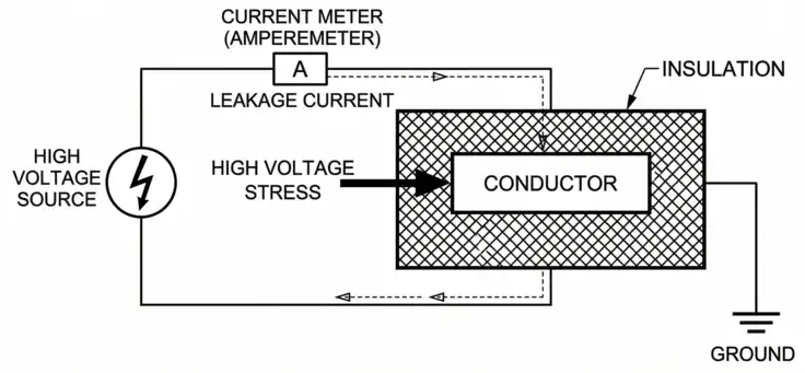
The working principle of the Hi Pot test is based on applying a controlled overvoltage to the insulation system and monitoring the leakage current that flows through it. A test voltage is applied between the conductor and the ground (or chassis), and the resulting current is measured.
In a healthy insulation system, only a very small amount of leakage current should flow. This leakage current is usually in the microampere range for most equipment. If the insulation has degraded or has a defect, the leakage current will be noticeably higher. If the insulation breaks down completely, a large current will flow and the test instrument will trip.
Think of it like testing a garden hose for leaks. You increase the water pressure beyond what you would normally use. If the hose holds, it is in good condition. If water sprays out through a weak spot, you found a defect. The Hi Pot test works the same way with electrical insulation.
The test instrument, called a Hi Pot tester or dielectric withstand tester, includes a variable high-voltage power supply, a current measurement circuit, and a trip circuit. The trip circuit automatically disconnects the voltage if leakage current exceeds the preset limit.
3. Types of Hi Pot Tests
There are two main types of Hi Pot tests based on the type of voltage applied. Each has its own advantages and use cases.
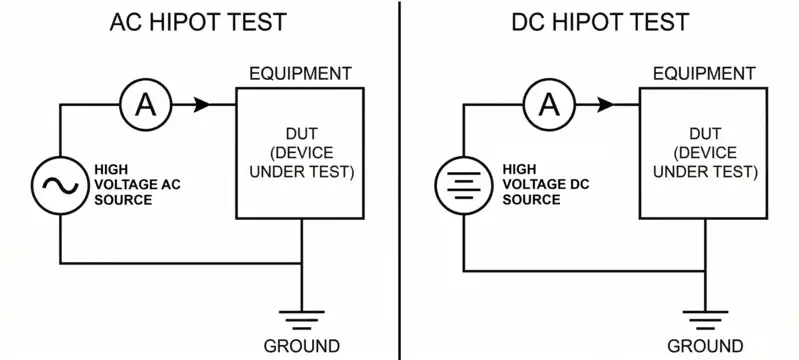
3.1 AC Hi Pot Test
The AC Hi Pot test uses alternating current at the power frequency (50 Hz or 60 Hz) as the test voltage. This is the most common type and is preferred for most factory and acceptance tests. The AC test stresses the insulation in both polarities during each cycle. This makes it effective at finding defects that might only appear under one polarity.
AC testing does not leave a residual charge on the equipment after the test is completed. This is a safety advantage. It is commonly used for motors, transformers, and cables during production testing.
3.2 DC Hi Pot Test
The DC Hi Pot test uses direct current as the test voltage. DC testing is often used in the field because the test equipment is lighter and more portable than AC test sets, especially for high-voltage testing.
DC testing charges the insulation capacitance during the initial application. Once the capacitance is fully charged, only the true leakage current remains. This allows the tester to measure the actual resistive leakage through the insulation more accurately.
However, DC Hi Pot testing does leave a residual charge on the equipment. The equipment must be properly discharged and grounded after the test.
4. Test Voltage Levels and Duration
The test voltage level depends on the rated voltage of the equipment and the applicable standard. A general rule of thumb used in the industry is:
AC Hi Pot Test Voltage = (2 × Rated Voltage) + 1,000 V
DC Hi Pot Test Voltage = AC Test Voltage × 1.414
The duration of the test is usually 60 seconds for production tests and can be up to 5 or 15 minutes for field or maintenance tests.
Here is a table showing some examples:
| Equipment Rated Voltage | AC Test Voltage | DC Test Voltage | Duration |
|---|---|---|---|
| 240 V | 1,480 V | 2,093 V | 60 seconds |
| 480 V | 1,960 V | 2,771 V | 60 seconds |
| 4,160 V | 9,320 V | 13,178 V | 60 seconds |
| 15,000 V | 31,000 V | 43,814 V | 60 seconds |
These values are general guidelines. Always refer to the manufacturer’s recommendations and the applicable industry standard for the exact test voltage and duration.
5. Equipment Used for Hi Pot Testing
A Hi Pot test setup requires specific equipment. Here is a breakdown of what is involved:
5.1 Hi Pot Tester (Dielectric Withstand Tester)
This is the primary instrument. It generates the required high voltage (AC or DC) and measures the leakage current. Modern Hi Pot testers have built-in trip circuits, timers, and digital displays. They come in benchtop models for laboratory or factory use and portable models for field use.
Popular manufacturers of Hi Pot test equipment include Megger, Hipotronics, Phenix Technologies, and Associated Research (now part of Ikonix).
5.2 Test Leads and Electrodes
High-voltage test leads connect the Hi Pot tester to the equipment under test. These leads are heavily insulated and rated for the test voltage. The electrodes or clips must make secure contact with the conductor and ground points.
5.3 Ground Connection
A solid ground connection is mandatory. The chassis or enclosure of the equipment under test must be connected to the Hi Pot tester’s ground terminal and to the facility’s ground system.
5.4 Personal Protective Equipment (PPE)
Insulated gloves rated for the test voltage, safety glasses, and insulated floor mats are required. A safety barrier or restricted access area should be set up around the test location.
6. Step-by-Step Hi Pot Test Procedure
Performing a Hi Pot test correctly requires careful preparation and a structured procedure. Rushing through any step can lead to inaccurate results or serious safety hazards. Below is a general step-by-step guide that covers the complete process from start to finish.
Step 1: Review the Applicable Standard
Start by identifying the correct standard for the equipment under test. Different equipment types follow different standards. For example, IEC 60034 applies to rotating machines and IEC 60950 applies to IT equipment. Each standard specifies the required test voltage, duration, and pass/fail criteria. Make sure you have the latest version of the document before proceeding.
Step 2: De-energize and Isolate the Equipment
Make sure the equipment is completely disconnected from any power supply or external circuit. Follow lockout/tagout (LOTO) procedures as per OSHA 29 CFR 1910.147. Verify the de-energized state using a voltage tester or multimeter. Never assume equipment is safe just because the switch is off. This step protects both the test operator and the equipment itself.
Step 3: Discharge and Ground the Equipment
Discharge any stored energy in capacitors, cables, or windings before touching any part of the system. Stored charge in capacitors can deliver a dangerous shock even after power removal. Ground all conductors using proper grounding straps or cables. This step eliminates residual voltage and creates a safe starting point for the test setup.
Step 4: Inspect the Equipment
Visually inspect the insulation surface for obvious damage such as cracks, burns, or discoloration. Check for contamination from dust, oil, or moisture that could affect test accuracy. Look at cable terminations and connection points for signs of wear. A quick visual check can sometimes identify problems before the electrical test is performed, saving time and preventing false failures.
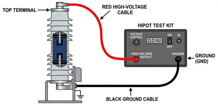
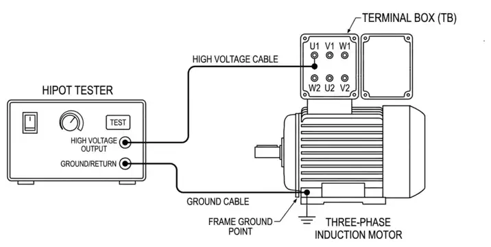
Step 5: Connect the Hi Pot Tester
Connect the high-voltage output lead of the tester to the conductor or winding you want to test. Connect the ground return lead to the chassis, frame, or equipment enclosure. Make sure all connections are tight and secure to avoid arcing at loose terminals. Keep test leads separated from each other and away from other objects to prevent accidental flashover.
Step 6: Set the Test Parameters
Set the test voltage, duration, and trip current on the Hi Pot tester according to the selected standard. The trip current acts as a safety threshold that stops the test if leakage becomes excessive. For small motors, a trip current setting of 5 to 10 mA is common. Always cross-check these values against the manufacturer’s recommendations for the specific equipment being tested.
Step 7: Apply the Test Voltage
Gradually increase the voltage from zero to the required test level. Do not apply the full voltage suddenly because a rapid voltage spike can damage healthy insulation. A ramp rate of about 500 V per second is common practice in most testing environments. This controlled increase allows you to monitor the equipment response and catch early signs of insulation weakness during the ramp-up phase.
Step 8: Hold the Voltage
Maintain the test voltage at the required level for the full specified duration. A standard hold time is usually 60 seconds, but some standards may require longer periods. Monitor the leakage current reading throughout this period. The current should remain stable and stay below the trip threshold. Any sudden spike or steady increase in leakage current may indicate insulation degradation.
Step 9: Reduce and Remove the Voltage
After the hold period is complete, gradually reduce the voltage back to zero. A controlled ramp-down protects the insulation from transient stress that can occur during abrupt shutoff. Do not disconnect the test leads while voltage is still applied. Removing leads under voltage creates arc flash risks and can damage the Hi Pot tester output terminals.
Step 10: Discharge and Ground the Equipment
For DC Hi Pot tests, discharge the equipment through a grounding stick or the tester’s built-in discharge circuit. DC tests leave a residual charge on insulation and capacitive components that must be safely removed. Wait until the voltage reading drops completely to zero before touching any conductors. This post-test discharge step is just as important as the pre-test grounding performed in Step 3.
Step 11: Record the Results
Document the test voltage, hold duration, leakage current readings, and pass/fail result in a formal test report. Include the date, equipment identification number, ambient temperature, and the name of the person performing the test. Proper documentation supports warranty claims, compliance audits, and future maintenance planning. Saved records also help track insulation condition trends over time.
7. How to Interpret Hi Pot Test Results
Interpreting the results of a Hi Pot test is straightforward in most cases. The test produces measurable data in the form of leakage current readings, voltage levels, and trip events. Based on this data, you can classify the outcome into one of three categories. Each outcome tells you something different about the condition of the insulation and the next steps you should take.
7.1 Pass
A pass result means the equipment withstood the full test voltage for the entire specified duration without any issues. The leakage current stayed well below the trip setting throughout the hold period and remained stable without sudden jumps. This outcome confirms that the insulation is in good condition and meets the requirements of the applicable standard. The equipment can be safely placed into service or returned to operation.
For example, if a motor is tested at 1500V DC for 60 seconds and the leakage current holds steady at 2 mA against a 10 mA trip limit, the test is a clear pass.
7.2 Fail (Breakdown)
A fail result occurs when the insulation breaks down during the test. A large surge of current flows through the insulation and the Hi Pot tester trips immediately to protect both the equipment and the operator. This outcome indicates a serious defect in the insulation such as a crack, void, or contamination path. The equipment should not be placed into service until the insulation fault is located and repaired.
For example, if the tester trips at 900V during a 1500V test, the insulation failed well below the required voltage. The failed component must be isolated, inspected, and either repaired or replaced before retesting.
7.3 Marginal
A marginal result falls between a clear pass and an outright failure. The equipment survives the full test duration and the leakage current stays within the trip limit. However, the leakage current is higher than expected or shows a gradual upward trend during the hold period. This behavior may indicate aging or deteriorating insulation that could fail in the near future under normal operating conditions.
For example, if the leakage current starts at 3 mA and slowly climbs to 7 mA during a 60-second hold with a 10 mA trip setting, the test is technically a pass but the trend raises concern. The equipment should be investigated further using other diagnostic methods like insulation resistance testing, polarization index measurement, or partial discharge testing. These additional tests help pinpoint the location and severity of the insulation weakness before making a final decision on serviceability.
8. Applications of the Hi Pot Test
The Hi Pot test is used across a wide range of electrical applications. Here are some of the most common ones:
8.1 Manufacturing and Production Testing
Every motor, transformer, cable, and switchgear assembly undergoes a Hi Pot test before leaving the factory. This is a quality control measure to catch defects in the insulation introduced during manufacturing.
8.2 Commissioning
Before new electrical equipment is energized for the first time, a Hi Pot test confirms that the insulation was not damaged during shipping, handling, or installation.
8.3 Preventive Maintenance
Periodic Hi Pot testing is part of many maintenance programs. It helps detect insulation degradation before a failure occurs during normal operation.
8.4 After Repairs
If insulation has been repaired or rewound (as in motor rewinding), a Hi Pot test verifies that the new insulation meets the required standards.
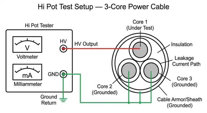
8.5 Cable Testing
Power cables, especially medium-voltage and high-voltage cables, are routinely tested using Hi Pot methods. IEEE 400 provides detailed guidance for field testing of shielded power cables rated 5 kV and above.
8.6 Appliance and Product Safety Testing
Consumer products and industrial equipment must pass a dielectric withstand test as part of their safety certification. Standards like UL 508A and IEC 61010 require this test.
9. Relevant ANSI and Industry Standards
Several ANSI and IEEE standards govern Hi Pot testing procedures, voltage levels, and acceptance criteria. Here are the most commonly referenced ones:
- ANSI/IEEE 95: This standard covers insulation testing for AC electric machinery with high voltage ratings above 230 V. It provides guidelines for the type and level of test voltage to be applied during acceptance and maintenance testing.
- ANSI/NEMA MG 1: NEMA MG 1 covers motors and generators. Section 12 and Section 20 of this standard specify the dielectric withstand test voltages for various motor ratings. For example, a motor rated at 2,300 V to 4,000 V should withstand a test voltage of (2 × rated voltage) + 1,000 V.
- IEEE 400: IEEE 400 is the guide for field testing and evaluation of insulation of shielded power cable systems rated 5 kV and above. It covers DC testing, VLF testing, and other methods used to evaluate cable insulation in the field.
- IEEE 62 (now part of IEEE 3007.2): This standard covers diagnostic field testing of electrical power apparatus, including motors, generators, transformers, and cables. It provides guidance on Hi Pot test procedures and interpretation of results.
- ANSI C2 (National Electrical Safety Code): The NESC requires proof testing of insulation on certain utility equipment before it is placed into service.
- UL Standards: Underwriters Laboratories (UL) standards such as UL 508A and UL 1741 also require dielectric withstand testing for industrial control panels and inverters during certification.
10. Differences Between Hi Pot Test and Megger Test
Many engineers and technicians confuse the Hi Pot test with the Megger test (insulation resistance test). Although both tests evaluate insulation, they are different in several ways.
| Feature | Hi Pot Test | Megger Test |
|---|---|---|
| Purpose | Tests if insulation can withstand overvoltage | Measures the resistance of insulation |
| Test Voltage | Much higher (thousands of volts) | Lower (usually 500 V to 5,000 V) |
| Measurement | Leakage current | Insulation resistance (in megaohms) |
| Nature | Go/no-go pass/fail test | Quantitative measurement |
| Standard Reference | ANSI/NEMA MG 1, IEEE 95, IEEE 400 | IEEE 43, ANSI/NETA MTS |
| Risk of Damage | Higher (due to high voltage) | Lower |
A Megger test is usually performed first. If the insulation resistance is acceptable, the Hi Pot test is performed as a more rigorous follow-up.
Example: Before performing a Hi Pot test on a medium-voltage motor, a technician first performs a Megger test at 2,500 V DC. The insulation resistance reads 500 megaohms, which is well above the minimum requirement. The technician then proceeds with the Hi Pot test at the standard voltage.
11. Safety Precautions During Hi Pot Testing
Hi Pot testing involves high voltage and can be lethal. Safety must be the top priority during every test. Here are the most important precautions:
- Only trained and qualified personnel should perform Hi Pot tests. This is not a test for beginners or untrained workers.
- Follow lockout/tagout procedures. Make sure the equipment is isolated from all power sources before testing begins.
- Set up a restricted area. Use barriers, warning signs, and flashing lights to keep unauthorized personnel away from the test area.
- Wear appropriate PPE. Insulated gloves, safety glasses, and insulated footwear should be worn at all times during the test.
- Never touch the equipment under test while voltage is applied. Keep your hands away from all connections and conductors.
- Always discharge the equipment after a DC Hi Pot test. Capacitive charge can remain on the insulation and deliver a dangerous shock even after the voltage source is removed.
- Use a dead-man switch. Many Hi Pot testers are equipped with a dead-man switch that cuts the voltage if the operator releases the button. This prevents continued energization if the operator becomes incapacitated.
- Ground all conductors not under test. Any conductor that is not being tested should be grounded to prevent accidental voltage buildup.
- Inspect test leads and connections before each test. Damaged leads or loose connections can cause arcing and create a safety hazard.
12. Common Mistakes to Avoid During Hi Pot Testing
Even experienced engineers can make mistakes during Hi Pot testing. Here are some common ones:
- Applying full voltage instantly. The voltage should always be ramped up gradually. A sudden application of high voltage can cause a transient overshoot that damages good insulation.
- Testing wet or contaminated equipment. Moisture and contaminants on the surface of insulation can cause surface flashover, which is not a true insulation failure. Clean and dry the equipment before testing.
- Not discharging equipment after DC tests. This is a dangerous oversight. Always discharge and ground the equipment before touching it.
- Using the wrong test voltage. Applying too high a voltage can damage good insulation. Applying too low a voltage does not adequately stress the insulation. Always refer to the applicable standard.
- Skipping the Megger test. Performing a Hi Pot test without first checking the insulation resistance can result in testing equipment with severely degraded insulation. This wastes time and may damage the Hi Pot tester.
- Poor grounding. An inadequate ground connection can lead to inaccurate leakage current readings and create a safety risk.
- Not recording results. Test results should always be documented for future reference, trending, and compliance purposes.
13. Hi Pot Testing for Electric Vehicles and Renewable Energy Systems
The growth of the electric vehicle industry and renewable energy sector has increased the demand for Hi Pot testing. Battery packs, inverters, chargers, and solar panel systems all require dielectric withstand testing to meet safety standards.
For electric vehicle batteries, the Hi Pot test checks the insulation between the high-voltage battery system and the vehicle chassis. Standards like SAE J1742 and IEC 62660 specify the test requirements.
Solar inverters and combiner boxes are tested per UL 1741 and IEC 62109. These tests confirm that the insulation between the DC input, AC output, and chassis can handle the required dielectric voltage.
This is a growing area of electrical testing and a valuable skill for engineers working in the clean energy and electric mobility sectors.
14. Hi Pot Test vs. Partial Discharge Test
Another test method used to evaluate insulation is the partial discharge (PD) test. The Hi Pot test determines if insulation can survive an overvoltage. The PD test detects small electrical discharges within the insulation that may indicate voids, contamination, or early-stage degradation.
The Hi Pot test is a pass/fail test. The PD test provides diagnostic information about the condition of the insulation. In many cases, both tests are used together. The Hi Pot test confirms the insulation can handle the voltage. The PD test identifies any internal defects that might lead to future failure.
For high-value equipment like large power transformers and generators, PD testing is often performed in addition to Hi Pot testing during factory acceptance and commissioning.
15. Conclusion
The Hi Pot test is a fundamental tool in the electrical engineer’s toolkit. It provides a direct and effective way to verify that insulation can withstand voltages higher than normal operating conditions. From factory floors to field installations, this test is performed on motors, transformers, cables, switchgear, inverters, and many other types of equipment.
The test is governed by well-established standards such as ANSI/NEMA MG 1, IEEE 95, IEEE 400, and various UL and IEC publications. Following the correct procedure, using the right test voltage, and observing strict safety practices are all necessary to perform the test properly and safely.
Engineers who master Hi Pot testing add a valuable skill to their professional capability. This test will continue to be a standard practice in power systems, manufacturing, renewable energy, and electric vehicle industries for years to come. Always refer to the latest edition of the applicable standard and follow your organization’s safety procedures when performing any high-voltage test.
16. Frequently Asked Questions (FAQs)
Hi Pot stands for High Potential. It is the high voltage applied during a dielectric withstand test to verify the integrity of electrical insulation.
The standard formula is (2 × rated voltage) + 1,000 V. For a 480 V motor, this equals (2 × 480) + 1,000 = 1,960 V AC. Always confirm with the applicable standard such as ANSI/NEMA MG 1.
A production or acceptance Hi Pot test usually lasts 60 seconds. Field maintenance tests may last 5 minutes or longer depending on the standard and the type of equipment.
If performed correctly at the proper voltage and duration, a Hi Pot test should not damage healthy insulation. However, applying excessive voltage or testing already degraded insulation can cause damage.
AC Hi Pot testing uses alternating current and stresses insulation in both polarities. DC Hi Pot testing uses direct current and is preferred for field testing because the equipment is more portable. DC testing requires proper discharging after the test.
No. A Megger test measures insulation resistance in megaohms at a relatively low voltage. A Hi Pot test applies a much higher voltage and checks if the insulation breaks down. They are complementary tests.
Yes. Field Hi Pot testing is commonly performed on installed cables, especially medium-voltage and high-voltage cables. IEEE 400 provides detailed guidance for this application.
Acceptable leakage current depends on the type and size of the equipment. For small motors, leakage current below 5 mA is common. For large cables and transformers, the acceptable level may be higher. Always refer to the manufacturer’s specifications and the applicable standard.