Ceiling fans are among the most essential and energy-efficient appliances found in households worldwide, particularly in tropical and subtropical regions. They provide comfortable air circulation at a fraction of the energy cost compared to air conditioning systems. In this article we will explore the technical aspects of ceiling fan circuitry, wiring, the critical role of capacitors, common troubleshooting methods, and essential safety practices.
The Anatomy of a Ceiling Fan Circuit
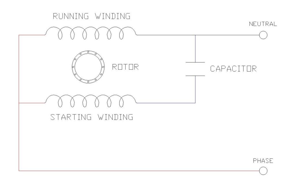
The ceiling fan circuit diagrams presented illustrate the fundamental electrical components and connections required for proper operation of a single-phase capacitor-start induction motor, which is the most common type of motor used in ceiling fans. Understanding these components is essential for anyone looking to install, repair, or maintain a ceiling fan.
Motor Windings
A ceiling fan motor contains two distinct windings that work together to create rotational motion. The running winding (also called the main winding) maintains continuous rotation once the fan has started, while the starting winding (auxiliary winding) provides the initial torque needed to overcome inertia and begin rotation. These two windings are spatially displaced by approximately 90 degrees within the stator of the motor.
Capacitor
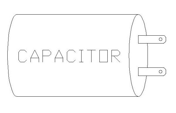
The capacitor is the most critical component in a ceiling fan’s electrical system. This electrolytic or film capacitor, typically ranging from 1.5 μF to 3.5 μF at 440V AC for residential fans, is connected in series with the starting winding. The capacitor’s primary function is to create a phase shift in the current flowing through the starting winding, which generates the rotating magnetic field necessary for the motor to start and run efficiently. When the capacitor introduces this phase difference—typically close to 90 degrees—the two windings produce magnetic fields that are out of phase with each other, creating a rotating effect that sets the rotor in motion.
Power Supply Connections
The circuit receives power from a standard single-phase AC supply, typically 220V in most countries including India. The power supply consists of three wires: the phase line (live wire, carrying the active current), the neutral line (providing the return path for current), and the ground wire (copper or green, providing safety against electrical surges). It is crucial that the switch and speed regulator are connected to the phase line rather than the neutral line for safety reasons.
Switch and Speed Regulator
A simple single-pole single-throw (SPST) switch controls the on/off function of the fan, while a speed regulator allows users to adjust the fan’s rotational speed by controlling the voltage supplied to the motor. Modern electronic regulators use capacitors and semiconductor devices for efficient speed control with minimal energy loss, whereas older resistive regulators dissipated energy as heat.
Terminal Block
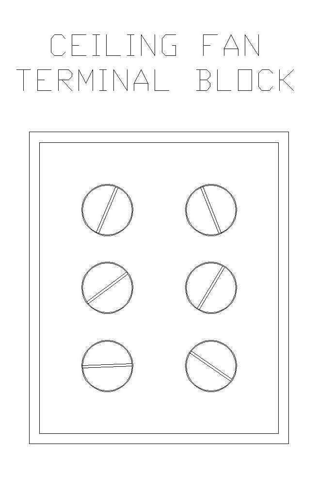
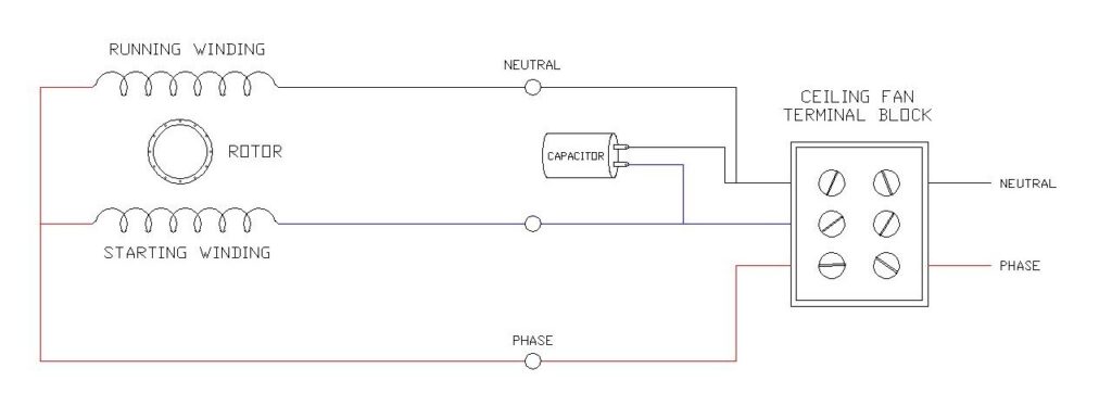
The ceiling fan terminal block provides organized connection points for all the electrical wires, including connections for the phase, neutral, running winding, starting winding, and capacitor. This standardized arrangement ensures safe and proper electrical connections during installation.
Ceiling Fan Capacitor Wiring Diagram
Step-by-Step Procedure for Replacing a Ceiling Fan Capacitor
- Disconnect Power
This is the most critical step for your safety. Turn off the power to the ceiling fan at the circuit breaker/switch. Use a non-contact voltage tester to confirm that there is no power at the fan’s switch and wiring. - Access the Capacitor
Remove the fan’s switch housing to get to the capacitor. The capacitor is typically a small, cylindrical-shaped component located near the fan’s motor. - Document the Wiring
Before disconnecting anything, take a photo of the current wiring configuration to remember how the new capacitor should be connected. - Disconnect the Old Capacitor
Use screw drivers to loose the screws to disconnect the wires from the Ceiling Fan Terminal block. - Connect the New Capacitor
Connect the new capacitor with with the terminal block, making sure they match the original wiring setup you documented. Twist the ends of wires with the same insulation color together in a clockwise manner and secure each connection with a wire nut and electrical tape. - Reassemble the Fan
Carefully tuck the wires and the new capacitor back into the housing. Reinstall the cover or canopy you removed earlier. - Test the Fan
Restore power at the circuit breaker/switch and test the fan at all speed settings to ensure it operates smoothly. If the fan works correctly, your replacement is complete.
Working Principle of Single-Phase Induction Motors
Ceiling fans employ single-phase induction motors, which operate on the principle of electromagnetic induction but face a unique challenge: they are not self-starting.
The Self-Starting Problem
When a single-phase AC supply is connected to the stator winding, it produces a pulsating magnetic field rather than a rotating one. The term “pulsating” describes how the magnetic field builds up in one direction, diminishes to zero, and then builds up in the opposite direction. According to the Double Revolving Field Theory, this pulsating field can be resolved into two rotating magnetic fields of equal magnitude rotating in opposite directions. When the rotor is at rest, these two fields produce equal and opposite torques that cancel each other out, resulting in zero net starting torque. Consequently, the motor cannot start on its own and requires an auxiliary mechanism.
The Capacitor Solution
The capacitor connected in series with the starting winding provides the elegant solution to the self-starting problem. When AC current flows through the circuit, the capacitor creates a phase shift between the current in the starting winding and the current in the running winding. In an ideal capacitor, the voltage lags behind the current by 90 degrees. This phase difference between the two windings creates a quasi-rotating magnetic field that develops the necessary starting torque to initiate rotor rotation.
Once the rotor begins to turn, even slightly, it enters the zone of the leading magnetic field and then lags behind the following field, causing the magnetic fields to sequentially cut the rotor conductors. This interaction generates electromotive force (EMF) and current in the rotor conductors through electromagnetic induction, which in turn produces torque that sustains the motor’s rotation. The capacitor remains in the circuit during operation (this is called a permanent split-capacitor or capacitor-run motor), continuing to provide phase correction and improving the motor’s power factor and efficiency.
Direction of Rotation
An interesting and practical aspect of ceiling fan motors is that the direction of rotation is determined by which winding the capacitor is connected to. If the capacitor is connected to the starting winding in one configuration, the fan will rotate in one direction. If the capacitor connection is switched to the running winding instead of the starting winding, the direction of rotation will reverse. This principle explains why some ceiling fans have a reverse switch that allows users to change the blade rotation direction for different seasons—pushing air down in summer for cooling or pulling air up in winter to circulate warm air that rises to the ceiling.
Maintaining Consistent Speed
After the motor starts, the capacitor continues to play a vital role by supplying the necessary electrical energy to maintain smooth and efficient operation. By storing and releasing electrical charge in a controlled manner, the capacitor provides a continuous and steady flow of electricity to the motor. This ensures stable speed regulation and helps the motor operate smoothly at various speed settings.
Common Capacitor Ratings and Types
For ceiling fans, the capacitor value typically ranges between 1.5 μF to 3.5 μF, depending on the motor specifications and fan size. Small, energy-efficient fans might use capacitors of 1.5 μF to 2 μF, standard residential fans typically use 2.25 μF to 2.5 μF, and high-speed or premium ceiling fans may require 3.15 μF to 3.5 μF capacitors.
Ceiling fans predominantly use two types of capacitors: electrolytic capacitors and film capacitors, specifically the CBB61 type. While electrolytic capacitors have lower cost, they have a shorter lifespan and are prone to drying out and failure. CBB61 film capacitors are the industry standard because they are non-polarized (can be connected in either direction), have a longer service life, and are more robust and reliable. For replacements, a CBB61 capacitor is always the recommended choice.
How to Identify Capacitor Failure
Recognizing the symptoms of a failing or failed capacitor is crucial for timely repairs. Common signs include:
- The fan hums but does not start rotating unless manually pushed
- Reduced speed even at high settings
- The fan runs but cannot change speeds
- Visible swelling, bulging, or discoloration of the capacitor casing
- Complete failure to operate
When a capacitor fails, the fan loses the phase shift necessary to create the rotating magnetic field, preventing proper startup and operation. Replacing a damaged capacitor is relatively simple—match the microfarad (μF) rating and voltage specification of the original capacitor, note the wiring connections, disconnect power, remove the old capacitor, and install the new one with identical connections.
Conclusion
Having knowledge on the electrical wiring, components, and operational principles of ceiling fans empowers homeowners to make informed decisions about installation, maintenance, and repairs. The diagrams illustrate the essential elements: the dual-winding motor configuration, the critical capacitor that enables self-starting and efficient operation, the power supply connections, and the speed control mechanism.