High-voltage electrical equipment such as power cables, transformers, switchgear, and rotating machines relies on insulation to keep electrical current flowing safely through the intended path. Over time, insulation can develop defects caused by manufacturing imperfections, thermal stress, mechanical damage, or aging. One of the earliest signs that insulation is deteriorating is the occurrence of partial discharge activity.
Partial discharge testing is the method used to detect, measure, and analyze these discharge events. It is one of the most widely used diagnostic tools in high-voltage engineering. Engineers use PD testing to assess insulation condition during factory acceptance tests, commissioning, and routine maintenance programs.
In this technical guide, we will discuss everything you need to know about partial discharge testing, including its working principle, types, detection methods, test equipment, measurement units, calibration procedures, acceptance criteria, coordination with other diagnostic tests, and relevant industry standards. Practical examples are included throughout to help you apply these concepts in real-world scenarios confidently.
1. What Is Partial Discharge?
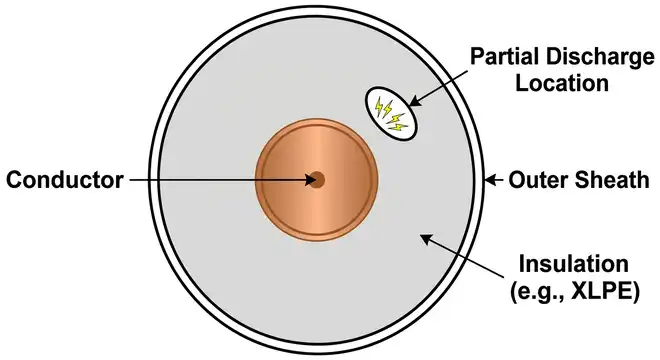
A partial discharge is an electrical discharge that only partially bridges the insulation between two conductors. The word “partial” is important here. The discharge does not travel all the way from one conductor to the other. It occurs locally in a weak spot within the insulation system.
To understand this more clearly, consider a cross-linked polyethylene (XLPE) power cable. During manufacturing, a tiny air-filled void can become trapped inside the insulation layer. Air has a much lower breakdown voltage than solid insulation material. So when the cable is energized at high voltage, the electric field across that void can exceed the air’s breakdown strength even though the bulk insulation has not failed. The air inside the void breaks down, producing a small electrical discharge. This is a partial discharge event.
That small discharge generates a short current pulse (lasting nanoseconds), releases a small amount of heat, emits electromagnetic waves (radio frequency pulses), produces light (ultraviolet), and generates an acoustic signal (ultrasound). PD detection systems use one or more of these byproducts to locate and measure the discharge activity.
PD magnitude is measured in picocoulombs (pC). One picocoulomb is one trillionth of a coulomb (10⁻¹² C). PD magnitudes in healthy insulation systems are often below 10 pC. Higher levels in the hundreds or thousands of picocoulombs indicate more severe insulation degradation and require further investigation.
2. Why Partial Discharge Testing is Important?
Insulation failures in high-voltage electrical equipment cause unplanned outages, equipment damage, safety incidents, and financial losses. The challenge is that insulation degradation is not always visible from the outside. A cable or transformer can look perfectly fine externally while the insulation inside is being slowly eroded by discharge activity.
PD testing gives engineers a window into the internal condition of insulation without opening the equipment. It can detect problems that are weeks or months away from causing a full failure. This allows maintenance teams to plan repairs or replacements in a controlled manner, rather than responding to an emergency breakdown.
For example, a 33 kV underground cable supplying a hospital might show no external damage after 15 years of service. A routine PD test reveals discharge activity of 850 pC at a specific location 420 meters from the substation. This tells the engineer that there is a developing defect at that location. The cable can be scheduled for repair during a planned maintenance window, before it causes a service interruption to the hospital.
3. Sources and Causes of Partial Discharge
Partial discharge activity is not random. It originates from specific types of insulation defects. Each defect type produces a characteristic PD signature that experienced engineers can use to identify the defect.
3.1 Manufacturing Defects
Manufacturing defects include voids (air bubbles trapped in solid insulation), inclusions (foreign particles embedded in the insulation during production), and surface contamination on insulation interfaces. These defects are present from the time the equipment is manufactured and may produce PD activity even at normal operating voltage.
3.2 Thermal Aging
Repeated thermal cycling causes insulation materials to expand and contract. Over many years, this mechanical stress creates microcracks and voids in the insulation, providing sites for discharge activity to develop.
3.3 Moisture Ingress
Water penetrating into cable joints, terminations, or transformer insulation lowers the local dielectric strength of the material. Water treeing (a phenomenon where moisture-filled channels grow through polyethylene insulation) is a well-known precursor to full cable failure and is often associated with high PD levels.
3.4 Electrical Stress Concentration
Sharp edges on conductors, protrusions in electrode surfaces, or poor geometry in cable accessories create localized concentrations of the electric field. The electric field at the tip of a sharp metallic protrusion can be many times higher than the average field in the insulation. PD activity initiates at these points.
3.5 Mechanical Damage
Physical damage to insulation from installation errors, dig-ins during civil works, vibration, or animal activity creates defect sites where PD activity can develop.
4. Types of Partial Discharge
Partial discharges are classified by their location and the physical mechanism that produces them. Each type has a different impact on insulation degradation and produces a different PD pattern.
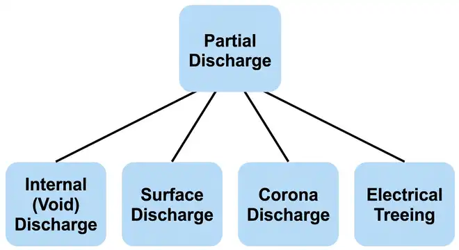
4.1 Internal (Void) Discharge
Internal discharges occur inside a void or cavity within the bulk insulation material. This is the most common type of PD in solid insulation systems such as XLPE cables and cast-resin transformers.
The void acts as a small capacitor in series with the surrounding insulation. The electric field across the void is determined by the permittivity ratio between the insulation and the void gas. Because air has a lower permittivity than XLPE (air εr ≈ 1.0 vs XLPE εr ≈ 2.3), the field across the void is higher, causing it to break down at a lower voltage than the surrounding insulation.
Internal voids cause progressive erosion of the surrounding insulation wall with each discharge event. Over time, the void grows larger, and the PD magnitude increases. This is one of the more damaging forms of PD activity.
4.2 Surface Discharge
Surface discharges occur along the interface between two different insulation materials or between an insulation material and a conducting surface. These are common at cable terminations, bushing interfaces, and insulator surfaces.
At a cable termination, for example, the transition between the XLPE insulation and the outer semiconducting screen creates a region of high tangential electric field. If the termination is not designed or installed correctly, surface discharges develop along this interface.
Surface discharges can spread across large areas of the insulation surface and cause carbonization (tracking) of the insulation material, which creates conductive paths that worsen over time.
4.3 Corona Discharge
Corona discharge occurs in the gas (air or SF₆) surrounding a sharp conductor or electrode. It is common on overhead transmission line hardware (corona rings, insulators) and at sharp protrusions on gas-insulated switchgear (GIS) conductors.
Corona in air produces a characteristic hissing or buzzing sound, ultraviolet light, ozone, and nitrogen oxide compounds. In GIS equipment insulated with SF₆ gas, corona produces by-products like sulfur dioxide (SO₂) and hydrogen fluoride (HF), which are chemically aggressive and can damage metallic surfaces.
Corona is generally less damaging to solid insulation than internal or surface discharges, but its by-products can attack nearby insulation materials over time.
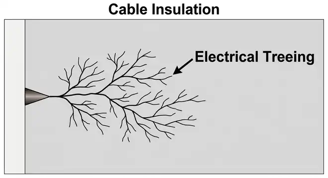
4.4 Electrical Treeing
Electrical treeing is a degradation mechanism rather than a distinct PD type, but it is closely associated with PD activity. It occurs in solid polymeric insulation when PD channels (narrow tracks of carbonized or eroded material) propagate through the insulation in a branching, tree-like pattern.
Once an electrical tree reaches a significant fraction of the insulation thickness, failure is usually imminent. Electrical trees grow faster under higher voltage stress and in the presence of moisture (forming water trees, which then convert to electrical trees under high field stress).
5. Working Principle of Partial Discharge Testing
Partial discharge testing works by applying a high voltage to the test object and then detecting the small current pulses generated by discharge events within the insulation. The test is performed according to the method defined in IEC 60270, which is the primary international standard for electrical PD measurement.
5.1 The Equivalent Circuit of PD
To understand how PD signals are detected, it helps to think about the equivalent circuit. An insulation system containing a void can be modeled as three capacitors:
- Ca: The capacitance of the void itself
- Cb: The capacitance of the insulation in series with the void
- Cc: The capacitance of the rest of the insulation in parallel with Ca and Cb in series
During a discharge event in the void, the voltage across Ca collapses rapidly (in nanoseconds). This sudden voltage collapse causes a redistribution of charge across the entire insulation capacitance system. The resulting charge pulse is what the PD measurement system detects at the terminals of the test object.
The apparent charge (q) measured in picocoulombs is the charge that flows into the test object terminals from the external circuit to restore the voltage balance after a discharge. The word “apparent” is used because this measured charge is not the actual charge transferred within the void. It is the externally measurable quantity that correlates with the internal discharge magnitude.
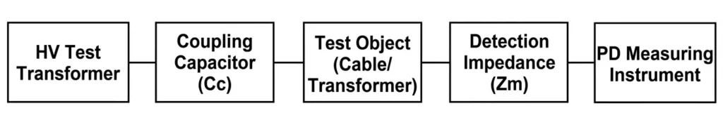
5.2 IEC 60270 Test Circuit
The standard PD test circuit as defined in IEC 60270 consists of the following components:
High Voltage Test Transformer (T): Supplies the test voltage to the object under test. The transformer must be low in PD itself (its own PD level should be below 5 pC for most applications). The test voltage is raised to the specified level during the test.
Filter/Blocking Impedance (Zm or Zf): Connected between the HV supply and the test circuit to prevent PD signals from the test object from propagating back into the power supply and being lost.
Coupling Capacitor (Ck): A high-voltage capacitor (typically 1 nF to 1 μF) connected in series or parallel with the test object. It provides a low-impedance path for the high-frequency PD current pulses to flow through the measuring circuit.
Test Object (Ca): The equipment under test — a cable, transformer, switchgear, or other HV component.
Detection Impedance (Zm): A measurement impedance (resistor or RC network) connected in series with the coupling capacitor. The PD current pulse flows through Zm, producing a voltage pulse that is fed to the measuring instrument.
PD Measuring Instrument: A wide-band or narrow-band instrument that amplifies, filters, and displays the PD signal. It measures the amplitude in picocoulombs and the repetition rate of discharge pulses.
5.3 Calibration
Before performing a PD test, the measurement system must be calibrated. A PD calibrator a small signal generator that injects a known charge pulse (e.g., 100 pC) directly at the terminals of the test object is used. The measuring instrument’s reading is adjusted to match the injected charge. This establishes the scale factor (pC per unit reading) for the measurement system.
Calibration is performed at the start of each test session and should be repeated if the test setup changes. IEC 60270 requires the calibration pulse rise time to be less than 60 nanoseconds.
6. Partial Discharge Detection Methods
Beyond the classical electrical method defined in IEC 60270, several other detection methods are used in practice each with different sensitivity, frequency range, and applicability.
6.1 Electrical Method (IEC 60270)
This is the reference method for PD measurement. It measures the apparent charge in picocoulombs. It is used in factory acceptance tests (FAT) for cables, transformers, and switchgear, and in laboratory testing of insulation specimens.
The measurement bandwidth is defined in IEC 60270:
- Wide-band instruments: 100 kHz to 1 MHz (or wider)
- Narrow-band instruments: Center frequency 50 kHz–1 MHz, bandwidth 9 kHz or 30 kHz
The electrical method provides quantitative results (pC values) that can be directly compared with acceptance criteria in standards. Its limitation is that it requires a controlled, low-noise environment because it is sensitive to external electrical interference.
6.2 Electromagnetic (Radio Frequency / UHF) Method
Partial discharges emit electromagnetic radiation across a wide frequency range, from kilohertz (kHz) to gigahertz (GHz). The Ultra-High Frequency (UHF) method uses sensors that detect PD signals in the 300 MHz to 1500 MHz frequency range.
The UHF method is widely used for PD detection in Gas-Insulated Switchgear (GIS) and Gas-Insulated Lines (GIL). Disk-shaped UHF sensors are mounted at dielectric windows on GIS enclosures to detect the electromagnetic waves emitted by internal discharges.
The advantage of the UHF method is that background electrical noise (from the power system or nearby electrical equipment) is concentrated at lower frequencies (below 100 MHz). By detecting PD signals in the UHF range, the measurement system effectively rejects most background noise, making UHF detection far more sensitive in electrically noisy substation environments.
UHF measurements are not directly calibrated in picocoulombs. They provide relative measurements (in millivolts or decibels relative to a reference). Pattern recognition and signal analysis are used to assess severity.
6.3 Acoustic Emission (AE) Method
Partial discharges generate mechanical stress waves (acoustic waves) that propagate through the surrounding material (solid insulation, oil, or metal tank walls). Piezoelectric acoustic sensors placed on the external surface of the equipment detect these waves.
The acoustic method is commonly used for:
- PD detection and location in oil-filled power transformers
- Detection of surface discharges in air-insulated substations
- Monitoring of GIS equipment
Acoustic sensors respond in the frequency range of 20 kHz to 300 kHz (ultrasound). By using multiple sensors at different locations on a transformer tank, engineers can triangulate the position of the PD source using the differences in signal arrival times. This technique is called time-of-flight (TOF) localization.
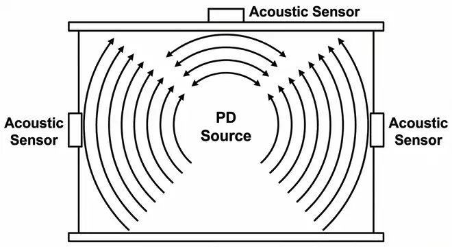
Practical Example: A 60 MVA power transformer at a 132 kV substation shows elevated dissolved gas analysis (DGA) results, with increasing acetylene (C₂H₂) levels indicating electrical discharges in the oil. An acoustic PD test using six sensors on the tank sides and lid is performed. The arrival time differences between sensors indicate the PD source is located near the high-voltage winding at approximately one-third of the winding height. This information guides the maintenance team in deciding to remove the transformer for internal inspection.
6.4 Chemical (Dissolved Gas Analysis – DGA) Method
For oil-filled equipment (transformers, oil-insulated cables), partial discharges in oil produce characteristic decomposition gases: hydrogen (H₂), methane (CH₄), ethylene (C₂H₄), and acetylene (C₂H₂). Dissolved gas analysis (DGA) provides an indirect indication of PD activity.
DGA is governed by IEC 60599 and IEEE C57.104. High hydrogen levels combined with elevated methane are characteristic of partial discharge activity. High acetylene indicates high-energy electrical arc discharges.
DGA is an indirect PD detection method. It does not provide the discharge magnitude in picocoulombs or pinpoint the location of the defect. But it serves as a valuable screening tool that prompts further investigation with acoustic or electrical PD methods.
6.5 Optical (UV Camera) Method
Corona discharge and some forms of surface discharge emit ultraviolet (UV) radiation. A UV-sensitive camera (solar-blind camera) can image this UV emission against a daylight background, revealing the location of corona activity on outdoor equipment like overhead line hardware, insulator strings, and open-type switchgear.
UV cameras are used during live-line inspections of overhead transmission lines and outdoor substations. They do not require the line to be de-energized, and they provide visual confirmation of the location and relative severity of corona activity.
6.6 High-Frequency Current Transformer (HFCT) Method
The HFCT method uses a clamp-on high-frequency current transformer placed around the earth bond or cable screen at a cable joint or termination. PD current pulses flowing in the cable screen or earth return path are detected by the HFCT.
The HFCT method is widely used for online PD monitoring of medium-voltage (MV) cables and switchgear because the sensor can be installed without interrupting service. It detects signals in the range of 1 MHz to 50 MHz.
Pulse shape analysis and time-difference of arrival (TDOA) between two HFCT sensors at each end of a cable section can be used to locate the discharge source along the cable length.
7. Online vs Offline Partial Discharge Testing
Partial discharge tests are performed either with the equipment de-energized and connected to a separate HV test source (offline testing) or with the equipment energized from its normal supply (online testing). Both approaches have their place in a maintenance program.
7.1 Offline PD Testing
In offline PD testing, the equipment is disconnected from the power system and energized using a portable HV test set. The test voltage is applied according to the standard test levels for the equipment type.
For medium-voltage (MV) cables, IEC 60502-2 and IEEE 400.3 specify offline PD test voltages. A typical offline PD test for a 12 kV cable system uses:
- Pre-stress voltage: 1.5 × U₀ (where U₀ is the rated phase-to-earth voltage = 6.35 kV for 11 kV system) → applied for 10–60 minutes
- PD measurement voltage: U₀ and 1.5 × U₀
Test voltage waveforms used for offline PD testing include:
- Power frequency (50/60 Hz): Standard method, matches normal operating stress
- Very Low Frequency (VLF) at 0.1 Hz: Requires much smaller test sets because capacitive reactive power is 500× less than at 50 Hz. Used for long cable circuits.
- Damped AC (DAC): An oscillating voltage waveform produced by discharging a capacitor through the cable capacitance. Used for medium-length cable circuits.
The main advantage of offline testing is that the background electrical noise from the operating power system is absent. This allows much more sensitive measurements (down to a few picocoulombs).
The limitation is that the equipment must be taken out of service, which is not always possible or economically justifiable for every asset.
Practical Example: A 6.35 kV (11 kV system) XLPE cable circuit 2.5 km long at an airport is tested offline using the VLF method. The test voltage is raised to 9.5 kV (1.5 × U₀) at 0.1 Hz. PD measurements at U₀ (6.35 kV) show a maximum reading of 320 pC at a location 1.8 km from the test end. The acceptance criterion for the cable system is 300 pC at U₀ (per the cable system supplier’s specification). The cable section is flagged for investigation.
7.2 Online PD Testing
In online PD testing, the equipment remains energized from its normal supply while PD measurements are taken. Sensors (HFCT clamps, UHF sensors, acoustic sensors) are attached to accessible external points without interrupting the circuit.
Online PD testing is used for condition monitoring of in-service assets like cables, switchgear, transformers, and motors. It does not require an outage and can be performed as part of a regular maintenance inspection.
The limitation of online testing is that the background electrical noise from the energized system (switching transients, corona from adjacent equipment, radio interference) can mask true PD signals. Advanced noise rejection techniques including pulse polarity discrimination, time difference of arrival filtering, and digital signal processing are needed to separate genuine PD pulses from background noise.
Online PD monitoring can also be performed on a continuous basis using permanently installed sensors connected to a monitoring system. This is called continuous online PD monitoring and is used on important assets where early warning of insulation degradation is needed.
Practical Example: A 33 kV gas-insulated switchgear (GIS) bay at a transmission substation is monitored using permanently installed UHF sensors. A continuous online monitoring system records PD data around the clock. After two months of normal baseline readings, the monitoring system detects a new UHF signal at one sensor location. Pattern analysis shows the signal characteristics of a free metallic particle moving inside the GIS enclosure. The bay is scheduled for inspection at the next available outage, and a 6 mm metallic particle is found and removed.
8. Partial Discharge Testing for Specific Equipment Types
8.1 PD Testing for Power Cables
Power cable PD testing is one of the most established PD testing applications. Both factory tests (during cable manufacture) and field tests (after installation) are performed.
Factory Testing: IEC 60840 (for HV cables above 30 kV) and IEC 62067 (for EHV cables above 150 kV) specify PD test requirements for cables during manufacture. The PD test is performed at elevated voltages (up to 2.5 × U₀ in some cases), and the cable must show no detectable PD above the instrument background level (typically < 5 pC).
After-Laying Tests: After a new cable circuit is installed and jointed in the field, an after-laying PD test is performed to verify that the joints and terminations were installed correctly. Cable accessories (joints, terminations) are the most common locations for PD defects in field-installed cable systems. IEEE 400.3 and HD 620 S1 provide guidance on after-laying PD test methods and acceptance criteria.
Cable PD Location: When a PD source is detected in a cable, the location of the defect must be found so that the defective joint or cable section can be repaired. Two methods are used for cable PD location:
- Time Domain Reflectometry (TDR): A reference pulse is injected at one end of the cable. The pulse travels to the defect, generates a reflection, and returns. The time delay between the injected pulse and the reflected pulse, divided by the pulse propagation velocity, gives the distance to the defect.
- Time Difference of Arrival (TDOA): Two PD sensors are placed at each end of the cable. The PD pulse from the defect arrives at each sensor at a slightly different time. The time difference, multiplied by the pulse velocity, gives the distance from each end to the defect.
8.2 PD Testing for Power Transformers
Power transformer PD testing is performed as part of factory acceptance tests (FAT) per IEC 60076-3. The test verifies that the transformer insulation (paper, pressboard, and oil) is free of significant discharge activity at the rated operating voltage.
PD tests are performed during the applied voltage test and induced voltage test. During the induced voltage test, the transformer secondary is energized to produce twice the normal primary voltage across the insulation at a higher frequency (100–200 Hz) to avoid core saturation. PD measurements are taken during and after the voltage application.
Acceptance criteria per IEC 60076-3:
- For transformers up to 72.5 kV: PD level ≤ 300 pC at 1.5 × Um/√3
- For transformers 72.5 kV to 300 kV: PD level ≤ 500 pC at 1.3 × Um/√3, measured at 1.1 × Um/√3
In the field, acoustic and UHF methods are used for in-service transformer PD monitoring as described earlier.
8.3 PD Testing for Gas-Insulated Switchgear (GIS)
GIS equipment is tested using UHF PD measurement during factory tests and after installation in the field. IEC 62271-203 and IEC/TR 62478 provide guidance on UHF PD testing of GIS.
The high sensitivity of the UHF method in GIS (due to low background noise in the UHF band) allows detection of very small PD events that would indicate the presence of metallic particles, protrusions on conductors, or defective spacers.
After field installation, GIS is subjected to a commissioning PD test at 1.2 × rated voltage (Um) for a specified duration. No UHF PD activity above the background level should be observed.
8.4 PD Testing for Rotating Machines (Motors and Generators)
PD testing of large motors and generators focuses on the stator winding insulation. The insulation system in a large motor (class F or H insulation, rated above 3.3 kV) uses mica-reinforced tape wrapped around the stator coils. Voids between the insulation layers or between the insulation and the ground wall are sources of PD activity.
Methods used for motor and generator PD testing include:
- Offline High-Voltage PD Test: The machine is disconnected and energized from a portable HV source. PD measurements are made per IEC 60034-27-1.
- Online Stator Slot Coupler (SSC) Method: Capacitive couplers installed in the stator slots detect PD during normal machine operation. This is an online PD monitoring technique per IEC 60034-27-2.
IEEE 1434 provides guidance on PD measurement in rotating electrical machinery.
Typical acceptance criteria for motor PD tests: PD levels below 1000 pC at operating voltage are generally acceptable for new machines. PD levels above 10,000 pC at rated voltage indicate serious insulation deterioration.
9. Phase Resolved Partial Discharge (PRPD) Analysis
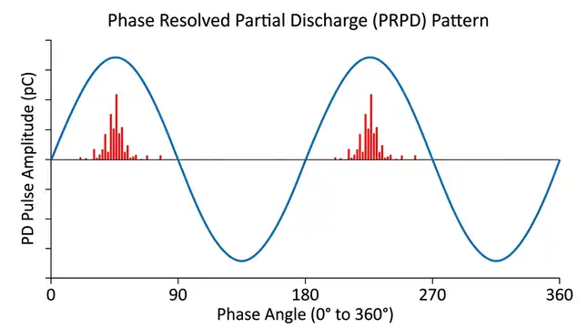
The Phase Resolved Partial Discharge (PRPD) pattern is one of the most useful tools for analyzing PD measurement data. A PRPD plot shows PD pulse amplitude (in pC) on the vertical axis, phase angle (0°–360°) on the horizontal axis, and pulse repetition density as a color or grayscale scale.
Different PD source types produce characteristic PRPD patterns:
9.1 Internal (Void) Discharges
PD pulses occur symmetrically in both the positive and negative half-cycles of the AC waveform, typically at phase positions of 45° and 225° (just after the voltage peaks where the rate of voltage change causes the void to discharge). The pattern looks like two symmetric “rabbit ears” in the PRPD plot.
9.2 Surface Discharges
These also appear in both half-cycles but at different phase positions than void discharges, and the pattern is often asymmetric between positive and negative half-cycles.
9.3 Corona Discharge
Corona from a sharp point on the high-voltage conductor typically produces pulses predominantly in one half-cycle (either positive or negative, depending on the polarity of the sharp point relative to the reference). This produces a single-sided PRPD pattern.
9.4 Electrical Noise (Non-PD)
Random electrical interference (from switching events, radio signals, or other equipment) produces a scatter of pulses that does not follow the AC phase consistently. True PD signals have a clear correlation with the phase of the applied voltage, which helps distinguish genuine PD from noise.
10. Noise Rejection in PD Testing
Background electrical noise is one of the main practical challenges in PD measurements. In a substation environment or industrial facility, numerous noise sources including power electronics, radio transmitters, switching transients, and corona from adjacent equipment can produce signals that look similar to PD pulses.
Several techniques are used to separate genuine PD signals from noise:
10.1 Gating
Time windows are set in the measuring instrument so that signals arriving at times known to coincide with external switching events are excluded from the measurement.
10.2 Differential Measurement
Two sensors are placed symmetrically around the test object. PD signals originating from inside the test object arrive at both sensors with a time delay (because PD pulses travel in both directions along the cable). External noise arrives at both sensors simultaneously. The differential amplifier subtracts the two sensor signals external noise cancels out, and internal PD signals are preserved.
10.3 Digital Filtering
Software algorithms analyze the pulse shape, rise time, and frequency content to classify pulses as PD or noise. Genuine PD pulses have characteristic rise times in the nanosecond range.
10.4 Shielding
The test object and test circuit are enclosed in a Faraday cage (shielded room) to block external electromagnetic interference from entering the measurement system. Factory PD tests are always performed in a shielded test bay.
10.5 Pulse Polarity Discrimination
PD pulses from different source locations on a cable arrive at a measurement point with opposite polarities (because they travel in opposite directions). This polarity information can be used to separate PD sources from external noise sources.
11. Standards for Partial Discharge Testing
PD testing is governed by a well-established set of international standards. These standards define test methods, acceptance criteria, and equipment requirements.
- IEC 60270: High Voltage Test Techniques: Partial Discharge Measurements
- IEEE 400: Guide for Field Testing and Evaluation of the Insulation of Shielded Power Cable Systems
- IEEE 400.3: Guide for PD Testing of Shielded Power Cable Systems in a Field Environment
- IEEE 400.4: Guide for Field Testing of Shielded Power Cable Systems Rated 5 kV and Above with Damped AC Voltage (DAC)
- IEC 60076-3: Power Transformers: Insulation Levels, Dielectric Tests and External Clearances in Air
- IEC 62271-203: Gas-Insulated Metal-Enclosed Switchgear for Rated Voltages Above 52 kV
- IEC 62478: High Voltage Test Techniques: Measurement of Partial Discharges by Electromagnetic and Acoustic Methods
- IEC 60034-27-1: Off-Line Partial Discharge Measurements on the Winding Insulation of Rotating Electrical Machines
- IEC 60034-27-2: On-Line Partial Discharge Measurements on the Stator Winding Insulation of Rotating Electrical Machines
- IEEE 1434: Guide to the Measurement of Partial Discharges in Rotating Machinery
- IEC 60599: Mineral Oil-Filled Electrical Equipment in Service – Guide to the Interpretation of Dissolved and Free Gases Analysis
- IEEE C57.104: Guide for the Interpretation of Gases Generated in Mineral Oil-Immersed Transformers
12. Partial Discharge Testing in the Context of Asset Management
Partial discharge testing sits within a broader framework of condition-based maintenance and asset management for high-voltage electrical equipment. It is one of several diagnostic tools used to assess asset health.
Other complementary diagnostic tests used alongside PD testing include:
- Tan Delta (Dielectric Loss) Testing: Measures the power factor or loss angle (tan δ) of the insulation. A high tan delta indicates overall insulation degradation (aging, moisture ingress). It provides a bulk insulation health indicator, whereas PD testing detects localized defects.
- Insulation Resistance (IR) Testing: Measures the DC resistance of the insulation using a megohmmeter. Simple and quick, but only detects gross insulation failures.
- Polarization Index (PI): The ratio of 10-minute IR to 1-minute IR. Provides a measure of insulation dryness and contamination.
- Time Domain Reflectometry (TDR): Locates impedance discontinuities in cables — open circuits, short circuits, and bad joints.
- Dissolved Gas Analysis (DGA): For oil-filled equipment, DGA provides indirect evidence of thermal and electrical discharge activity inside the equipment.
The combination of PD testing with tan delta, DGA, and infrared thermography provides a more complete picture of insulation health than any single test alone. Asset managers use these test results together to prioritize maintenance actions and investment decisions.
13. Conclusion
Partial discharge testing is one of the most informative diagnostic tools available to high-voltage engineers today. It moves maintenance from a fixed time-based schedule to a condition-based approach testing and acting when the insulation condition actually warrants it, rather than simply following the calendar.
From detecting a void in a newly manufactured cable at the factory, to locating a developing defect in a 20-year-old underground cable system, to monitoring a critical power transformer in a busy substation, PD testing provides actionable information about insulation health that no other single test can offer.
The combination of the standard electrical method (IEC 60270), UHF detection, acoustic monitoring, and HFCT-based online testing gives engineers a full toolkit to cover almost any equipment type and testing situation. Learning to apply these methods correctly, interpret the results in context, and integrate PD data with other diagnostic tests is a valuable and practical engineering skill.
14. Frequently Asked Questions (FAQs)
A partial discharge is a small electrical spark that occurs inside or on the surface of the insulation in high-voltage electrical equipment. The spark does not cause immediate failure because it does not completely bridge the gap between conductors. But each spark erodes a tiny amount of insulation. After thousands or millions of discharge events, the insulation becomes thin enough for a full breakdown to occur.
Partial discharge magnitude is measured in picocoulombs (pC). One picocoulomb equals 10⁻¹² coulombs.
A hipot (high potential) test applies a high voltage to the insulation to check if it can withstand the voltage without breaking down. It is a pass/fail test either the insulation survives or it fails (causing complete breakdown). A partial discharge test, on the other hand, measures the small discharge activity that occurs in weak spots of the insulation without causing breakdown. PD testing is diagnostic that reveals the condition of the insulation and detects developing defects, whereas hipot testing only confirms whether the insulation can hold a given voltage at a single moment.
For a new factory-tested HV cable per IEC 60840, the PD level should be below the measurement system’s background noise (essentially zero, or less than 5 pC). For a cable after field installation with joints and terminations, an acceptance criterion of 100–300 pC at the rated phase-to-earth voltage (U₀) is commonly specified, depending on the cable voltage class.
Yes. Online PD testing allows measurements to be taken while the equipment is energized from its normal supply. Methods used for online PD testing include HFCT sensors on cable sheaths, UHF sensors on GIS, acoustic sensors on transformer tanks, and stator slot couplers on motor windings.
False PD readings (also called noise or interference) can come from many sources: corona from adjacent equipment or overhead lines, radio frequency transmitters (mobile phones, walkie-talkies), fluorescent lighting ballasts, power electronics (variable frequency drives, rectifiers), arcing contacts in switchgear, and loose ground connections.
IEC 60076-3 governs dielectric tests for power transformers, including partial discharge tests.
Two main methods are used for cable PD location. The first is Time Domain Reflectometry (TDR): a reference pulse is injected at one end of the cable, and the time delay of the reflected pulse from the defect is measured to calculate the distance. The second is Time Difference of Arrival (TDOA): sensors at both ends of the cable measure the time at which the PD pulse arrives at each end. The difference in arrival times gives the distance from each end to the defect.
A Phase Resolved Partial Discharge (PRPD) pattern is a graphical display that shows PD pulse amplitude versus the phase angle of the applied AC voltage (0°–360°). Different types of PD sources (voids, surface discharges, corona, noise) produce characteristic patterns on the PRPD plot.
The frequency of PD testing depends on the equipment type, voltage class, age, and criticality. For new equipment, PD testing is part of the factory acceptance test and commissioning test — both mandatory. For in-service equipment, PD testing is typically included in a condition-based maintenance (CBM) program. New cable installations might be tested every 3–5 years. Older cables (over 15 years of service) or cables in aggressive environments might be tested every 1–2 years. Transformers at critical substations may be tested annually using DGA, with acoustic PD tests triggered if DGA shows abnormal gas levels.