SOTF (Switch On To Fault) Protection scheme is one of the most important innovations in recent power system protection. This protection function has become increasingly important in modern high-voltage transmission systems as utilities strive to improve reliability, reduce unnecessary outages, and maintain system stability. Unlike conventional protection methods that can be delayed or prone to false operation, SOTF protection offers a unique solution by detecting faults that occur precisely when a circuit breaker closes the transmission line.
In this technical guide we will discuss in-depth about SOTF protection principles, operation mechanisms, advantages, and practical applications in real-world power systems.
1. What is SOTF (Switch On To Fault) Protection?
SOTF (Switch On To Fault) protection is a specialized protection function designed to detect faults that occur immediately when a transmission line circuit breaker closes.
In simple terms, it is a high-speed protective scheme that activates when a circuit breaker attempt to energize a transmission line and a fault condition exists at that precise moment. The fundamental purpose of SOTF protection is to prevent unnecessary tripping of backup protection relays that would normally be activated by transient phenomena occurring during the line closing operation.
The term “Switch On To Fault” literally means switching on (closing the circuit breaker) directly onto a fault (an electrical fault condition on the transmission line). This situation is particularly challenging because the transient overvoltages and overcurrents generated during the closing operation can be mistaken for actual faults if not properly discriminated.
2. Why SOTF Protection is Necessary
When a transmission line is de-energized due to a previous fault and the circuit breaker is manually or automatically reclosed to restore power, the breaker closing operation generates significant transient currents and voltages. These switching transients can create stress on protective relays and equipment, potentially triggering unnecessary trips that interrupt service to consumers. In the worst case, if the line is reclosed onto a still-present permanent fault, the system must handle the extremely high current that flows from the healthy sections of the network.
SOTF protection addresses this need by:
- Distinguishing between switching transients and real faults during the critical moments when a breaker closes
- Blocking protection relays temporarily to prevent false operation from transient signals
- Allowing automatic reclosure to succeed for temporary (transient) faults that self-clear within milliseconds
- Rapidly detecting and isolating permanent faults that cannot self-clear
- Protecting equipment from damage that would occur if unnecessary trips happened repeatedly
Without SOTF protection, transmission line protection systems would face a dilemma: either they would be too sensitive and operate on switching transients (causing unnecessary blackouts), or they would be insensitive and miss actual faults (compromising system safety).
3. Technical Principles of SOTF Protection
3.1 Transient vs. Permanent Fault Discrimination
The core principle underlying SOTF protection is the ability to rapidly distinguish between transient faults and permanent faults.
A transient fault is a temporary fault condition that clears itself within a few cycles to tens of milliseconds. Common examples of transient fault include lightning strikes, arcing caused by wind-blown conductors touching, etc.
A permanent fault is a sustained fault condition that cannot clear itself and requires human intervention, such as a broken conductor or physical damage to the line.
The transient phenomenon during breaker closing creates:
- Magnetizing inrush currents flowing through series inductance of the transmission line
- Capacitive discharge currents from the capacitive nature of the transmission line
- Oscillatory transient voltages with frequencies much higher than power frequency
- Rapid rate of change of current (di/dt) and voltage (dv/dt)
SOTF protection algorithms analyze these characteristics. Permanent faults exhibit fundamentally different electrical signatures: they maintain elevated steady-state current magnitudes, contain specific harmonic content, and generate sustained overvoltages at power frequency rather than transient frequencies.
3.2 Signal Analysis and Blocking Duration
Modern SOTF protection schemes employ sophisticated signal processing techniques to analyze incoming current and voltage waveforms. The protection function typically operates within an extremely short time window of 10 to 50 milliseconds after the breaker closes. During this blocking period:
- The protection relay receives and analyzes signals from current transformers and voltage transformers
- Advanced algorithms compute fault indices based on signal characteristics
- The system determines whether conditions indicate a fault or merely transient switching phenomena
- A blocking signal prevents downstream protection devices from operating incorrectly
The blocking duration is carefully selected based on the transmission line parameters and the maximum duration of transient phenomena expected. After the blocking period expires, the system reassesses conditions. If the fault has cleared (indicating a transient), automatic reclosure is allowed. If the fault persists, trip signals are issued immediately.
3.3 Detection Algorithms
SOTF protection relies on several signal processing methods to identify fault conditions:
- Discrete Wavelet Transform (DWT): This technique decomposes the fault signal into different frequency components, separating transient high-frequency switching signals from power-frequency fault currents.
- Stockwell Transform: A time-frequency analysis method that provides better frequency resolution than traditional approaches, particularly useful for identifying the emergence and decay of transient signals.
- Hilbert Transform: Generates the analytic signal representation, allowing extraction of amplitude and phase information that clearly distinguishes fault types.
- Traveling Wave Detection: Advanced systems monitor high-frequency traveling waves propagating along the transmission line, which provide information about fault location and type.
- Waveform Distortion Analysis: Examines how quickly the current or voltage waveform deviates from expected sinusoidal shape, which is instantaneous for real faults but temporary for switching transients.
These algorithms run continuously during the blocking interval, maintaining millisecond-level precision in their calculations. Modern microprocessor-based protective relays can execute these complex computations in real-time. This enables reliable SOTF protection even for the most challenging fault scenarios.
4. Operating Principles and Mechanism
4.1 Step-by-Step Operation of SOTF Protection
The operation of SOTF protection can be understood through a sequential process:
Step 1: Circuit Breaker Closing Initiated
The process begins when a control command closes the transmission line circuit breaker. This might be a manual operator action or an automatic reclose command following a previous fault clearance. At this instant, the SOTF protection function becomes active and begins monitoring incoming signals.
Step 2: Transient Waveform Analysis
As the breaker contacts touch and the transmission line begins to energize, current and voltage signals are sampled at very high frequency (typically 1-2 kHz or higher). These waveforms contain both power-frequency components and high-frequency transient components superimposed upon them. The signal processing engine begins decomposing these complex waveforms.
Step 3: Fault Index Calculation
Using one or more of the signal processing techniques described above, the SOTF algorithm calculates fault indices representing the likelihood of a fault condition. A transient switching phenomenon would produce lower indices, while a real fault would generate high fault indices. The calculation occurs over successive half-cycles of the power frequency (approximately 10 milliseconds at 50 Hz).
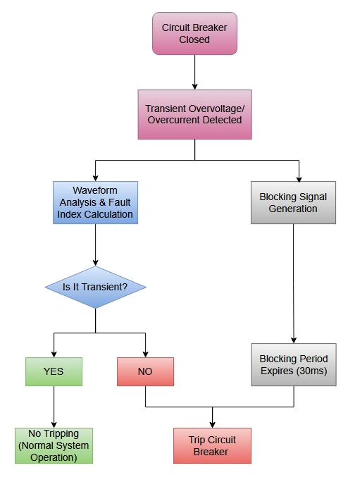
Step 4: Blocking Signal Generation
If the initial fault indices are low, indicating switching transients rather than faults, the SOTF protection immediately generates a blocking signal. This signal is transmitted to the main protection relay and backup relays, instructing them to ignore their normal trip logic for the duration of the blocking period. The blocking prevents false operation even if other relays detect the transient signals.
Step 5: Continuous Reassessment
Throughout the blocking period, the SOTF algorithm continues monitoring and analyzing the signal characteristics. If new information indicates an actual fault (fault indices increase beyond thresholds), the protection can command an immediate trip even before the blocking period expires.
Step 6: Decision After Blocking Period
When the blocking period expires (typically 20-50 milliseconds after breaker closing), the SOTF protection reassesses the line condition:
- If fault indices remain low and current has settled to normal levels, a transient fault is confirmed, no action/automatic reclosure is permitted
- If fault indices are elevated and current remains abnormally high, a permanent fault is confirmed, and trip commands are issued
Step 7: Relay Trip Decision
The SOTF output signal is combined with outputs from other protection functions (distance relay, overcurrent relay, differential relay) to make a final trip decision. In case of a permanent fault, all protection elements agree on a trip, and the circuit breaker opens rapidly to isolate the faulted line.
5. Example Scenario
To illustrate SOTF protection operation in practical, consider the following practical scenarios:
5.1 Scenario 1: Line Auto-Reclosure with Transient Fault
A 400 kV transmission line is struck by lightning, causing a phase-to-ground fault. The overcurrent relay senses excessive current and issues a trip command, opening the circuit breaker within 3-4 cycles. The lightning arc extinguishes as the breaker opens, clearing the transient fault. The system then commands an automatic reclose after a delay of 0.3-0.5 seconds (300-500 milliseconds), which is standard practice.
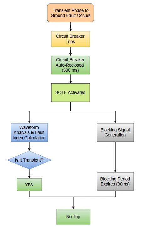
When the breaker closes again at t=0, the SOTF protection immediately activates. As the line re-energizes, magnetizing inrush current flows, and transient voltages oscillate at high frequency. The SOTF algorithm analyzes these signals, recognizing the characteristic signatures of switching transients.
It calculates low fault indices because:
- Current exhibits the classical exponential decaying magnetizing inrush pattern rather than maintaining a fault current magnitude
- Voltage contains significant 2-10 kHz oscillations from the line’s LC circuits
- The rate of change of current (di/dt) is very high but decreasing
- Zero-sequence current is minimal because no ground fault is present
The SOTF protection immediately issues a blocking signal, preventing the overcurrent relay from tripping on the inrush current. The blocking lasts for 30 milliseconds. During this time, the transient voltages and currents decay naturally, and by the time blocking expires, all signals have returned to normal values.
The SOTF function then allows normal operation to continue, and the line remains energized. A successful automatic reclosure has occurred, restoring service without any outage.
5.2 Scenario 2: Auto-Reclosure onto Permanent Fault
Now consider a different scenario where a permanent fault exists when the breaker closes:
A transmission line conductor breaks due to strong wind, creating a phase-to-ground fault. The breaker opens, and an automatic reclose is commanded.
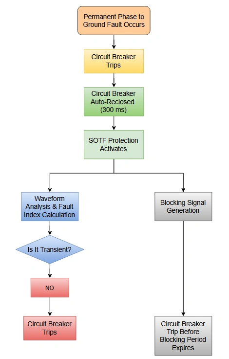
When the breaker closes at t=0, both the transient signals from switching AND sustained current from the permanent fault are present simultaneously.
The SOTF algorithm begins analyzing. Initially, like the previous scenario, transient components are present. However, the algorithm observes that after the transient oscillations decay (by t=20 milliseconds), the current remains elevated at a value consistent with solid fault current. The voltage remains depressed, not recovering to normal levels. Fault indices, which initially increased due to the transient, continue to rise as the transient component decays but the permanent fault signature persists.
By t=25 milliseconds, the SOTF protection recognizes the persistent fault condition. Even before the blocking period would naturally expire at t=40 milliseconds, the SOTF issues a trip command. The circuit breaker opens immediately, clearing the permanent fault and preventing damage to equipment.
The transmission line remains de-energized until the physical conductor break is repaired.
6. Components and Equipment Required for SOTF Protection
6.1 Protective Relays
SOTF protection is implemented within modern microprocessor-based intelligent electronic devices (IEDs), also called digital protective relays or numerical relays. These devices differ fundamentally from older electromechanical relays because they:
- Continuously sample analog voltage and current signals at high frequency
- Perform digital signal processing to extract useful information
- Execute complex algorithms to make protection decisions
- Communicate with other relays and control systems using standard protocols
Popular commercial protective relays offering SOTF functionality include:
- ABB REF 541 and REF 642 series: Industry-standard relays with comprehensive transmission line protection
- Siemens SIPROTEC 7 and SIPROTEC 5 series: Modern digital relays with advanced SOTF algorithms
- Alstom P641 and P643: Relays specifically designed for transmission line applications
- Schweitzer SEL-351 and SEL-421: Comprehensive line relays with SOTF blocking capabilities
6.2 Current and Voltage Transformers
High-accuracy current transformers (CTs) and voltage transformers (VTs) are essential for providing representative signals to the SOTF protection relay. These devices convert the high-voltage, high-current primary signals into measurable secondary signals:
- Current transformers: Typically provide 5A or 1A secondary currents, with accuracy class 0.2 or better
- Voltage transformers: Provide 110V or 100V secondary voltage, with accuracy class 0.2 or better
- Broadband compatibility: Transformers must accurately represent both power-frequency and transient high-frequency signals
- Saturation prevention: Must have adequate core cross-section to avoid saturation during high-current transients
6.3 Fiber Optic Communication
Many modern SOTF protection schemes transmit blocking signals between relays at different line terminals using fiber optic communication. Fiber optics are preferred because:
- They provide galvanic isolation, eliminating ground-loop interference
- They operate at high speed (speed of light), suitable for millisecond-precision blocking
- They are immune to electromagnetic interference
- They support redundancy for reliability
6.4 Automatic Reclosing Logic
SOTF protection works in conjunction with automatic reclosing (AR) logic, which controls when and how the circuit breaker attempts to reclosing:
- Fast AR: Closes within 0.1-0.5 seconds after opening (suitable for transient faults)
- Slow AR: Closes after 10-30 seconds (allows time for temporary conditions to clear)
- Dead Time: The delay between opening and reclosing, during which the line naturally discharges
- Reclosure Lockout: After a preset number of failed reclosure attempts, the system locks out further reclosure to prevent damage
7. SOTF Protection Settings and Adjustment
Proper configuration of SOTF protection requires setting several important parameters:
7.1 Blocking Duration (Delay Time)
The period during which protection relays are blocked from operating. Typical values range from 20 to 100 milliseconds, though 30-50 milliseconds is common. This must be long enough to allow transient signals to decay completely:
- Too short: Permanent faults might not be distinguished from transients; protection may trip after blocking expires when it should have waited
- Too long: Delays in clearing permanent faults, which increases equipment stress and risks to system stability
7.2 Fault Detection Threshold
The level at which signals are considered indicative of a fault rather than normal transients. This is expressed as a multiple of nominal current:
- Phase overcurrent threshold: Typically 1.5-2.5 times maximum expected normal current (MVA loading ÷ (sqrt(3) × voltage))
- Ground current threshold: Typically 0.3-0.7 times phase overcurrent threshold
- High-frequency current components: Defined based on expected transient magnitudes
7.3 Unblocking Criteria
The conditions under which the SOTF blocking is removed even before the blocking duration expires:
- If fault current exceeds a high threshold (indicating permanent fault)
- If voltage remains depressed beyond expected transient duration
- If traveling wave signals indicate fault presence
- If the differential current signal (three-phase sum) indicates genuine phase-to-ground fault
7.4 Hysteresis and Debouncing
Small additional delays prevent false operation from noise in the measurement signals, typically 1-5 milliseconds.
8. Commissioning Procedures
When a transmission line is first equipped with SOTF protection, several tests must be performed:
8.1 Signal Path Verification
- Inject known currents into current transformers and verify relay reception
- Apply known voltages to voltage transformers and confirm relay recognition
- Verify proper polarity of all signals
8.2 Blocking Function Test
- Simulate fault signals during “breaker closing” and confirm blocking signal generation
- Verify that connected relays actually block their trip logic during the blocking period
- Test blocking with both local and remote fault signals
8.3 Transient Discrimination Test
- Apply simulated fault waveforms representing transient conditions
- Verify that SOTF correctly identifies these as non-fault conditions
- Confirm that blocking allows subsequent auto-reclosure
8.4 Permanent Fault Detection Test
- Apply sustained fault current signals
- Verify that SOTF identifies permanent fault conditions
- Confirm rapid trip signal generation
8.5 Real-Time Digital Simulator (RTDS) Testing
- Use electromagnetic transient (EMT) simulation software to model the transmission line
- Replay captured fault scenarios
- Verify relay response under realistic conditions
9. Setting Calculation Examples
For a 400 kV transmission line with these parameters:
- Transmission line impedance: Z = (0.02 + j0.35) Ω/km
- Line length: 200 km
- Total line impedance: Z_line = 4 + j70 Ω
- Maximum phase-to-ground fault current: 25 kA
- Normal maximum line current: 2000 A
- Current transformer ratio: 2000:5
The SOTF protection settings would be:
- Blocking duration: 40 ms (allowing ~2 cycles at 50 Hz for transient decay)
- Phase overcurrent threshold: 2.5 × 2000 A = 5000 A (CT secondary: 12.5 A)
- Ground current threshold: 0.5 × 5000 A = 2500 A (CT secondary: 6.25 A)
- Unblocking threshold: 0.75 × 25 kA = 18.75 kA (CT secondary: 46.9 A)
These settings are then verified by testing against the expected inrush current during line closing, which might be 5-8 kA at the moment of breaker contact.
10. Comparison with Alternative Protection Methods
10.1 SOTF vs Distance Protection
Distance protection (impedance-based relaying) is the most common primary protection for transmission lines. It measures the apparent impedance seen by the relay and compares it to the impedance of the protected line to determine if a fault exists.
Key differences:
- SOTF Advantages: Specific to switching transient discrimination; operates with extreme speed; requires no line parameter knowledge
- Distance Protection Advantages: Provides continuous protection throughout fault scenario; covers entire line length; well-established and proven technology
Best Practice: Most modern systems use SOTF as a specialized function working in conjunction with distance protection, not as a replacement.
10.2 SOTF vs Differential Protection
Differential protection compares current entering and leaving a protected section; if they differ, a fault exists. While differential protection offers excellent discrimination capability:
- Differential Protection Disadvantages: Requires communication between line terminals; vulnerable to CT saturation; more complex implementation
- SOTF Advantages: Requires no communication; operates on local signals only; very fast response
10.3 SOTF vs Overcurrent Protection
Simple overcurrent relays detect high current without sophisticated logic. SOTF improvements:
- SOTF Advantages: Distinguishes transients from faults; reduces false operation; enables higher sensitivity
- Overcurrent Protection Advantages: Simple, low-cost, requires minimal settings

11. Conclusion
In the utility industry, there’s a saying: “A protection system that never trips is not protecting—it’s failing.” Conversely, a protection system that trips too frequently, even when protecting, is also failing because it interrupts service unnecessarily. SOTF (Switch On To Fault) Protection helps utilities achieve the delicate balance between these extremes—protecting when necessary while avoiding nuisance trips that damage customer relations and reduce equipment life.