STUB Protection is an important protective function in modern electrical power systems, particularly in substations employing the One and Half Breaker scheme. It serves as an overcurrent-based protection mechanism designed to detect and clear faults occurring in the unprotected stub section between the circuit breakers and the line isolator when a transmission line is taken out of service for maintenance.
In this technical guide we will explore every aspect of STUB Protection, its principle of operation, configuration, and practical applications in transmission line protection.
1. What is One and Half Breaker Scheme
1.1 What is the One and Half Breaker Scheme?
The One and Half Breaker scheme (also known as the 1½ breaker scheme) is an advanced substation configuration used extensively in high-voltage transmission systems to provide flexibility, reliability, and operational efficiency.
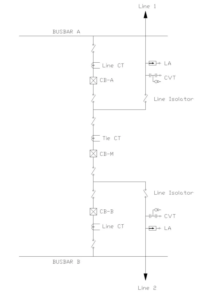
In this scheme, there are two busbars (Bus A and Bus B) and three circuit breakers connected in a specific arrangement. The configuration consists of:
- Two line circuit breakers (CBA and CBB): Each one associated with one transmission line or feeder
- One tie circuit breaker (CBM): Connected between the two busbars to allow power flow between them
- Two Feeders: Feeder 1 and Feeder 2, each with its own isolator (also called disconnect switch)
This arrangement allows each feeder to either receive power from one or both busbars through the three circuit breakers, or supply power to one or both busbars through the same three circuit breakers.
1.2 Operating Principle of One and Half Breaker Scheme
Under normal operating conditions, all three circuit breakers remain closed. This allows Busbar A to supply power to Line 1 through circuit breaker CBA, and simultaneously Busbar B supplies power to Line 1 through the tie circuit breaker CBM. Similarly, Busbar B supplies power to Line 2 through circuit breaker CBB, and simultaneously Busbar A supplies power to Line 2 through the tie circuit breaker CBM.
The tie breaker CBM ensures that both busbars can share the power supply to both lines.
The real operational challenge arises when one of the transmission lines needs to be taken out of service for maintenance, inspection, or repairs. During such maintenance operations, the following sequence occurs:
Before taking Line 1 out of service:
All three circuit breakers remain closed (CBA, CBB, and CBM). The line isolators are also closed, maintaining full power flow from both lines into the busbars. Both line distance relays receive current (CT) and voltage (CVT) signals. The entire transmission line is protected by the distance protection scheme.
When Line 1 is taken out of service:
After opening circuit breakers CBA and CBM, the Line 1 isolator is opened to disconnect Line 1 from the substation. Circuit breakers CBA and CBM are then reclosed to restore redundancy for Line 2, which remains energized by both Busbar A and Busbar B through all three circuit breakers (CBA, CBB, and CBM). Both busbars continue normal operation, maintaining power supply to Line 2.
1.3 The Unprotected Stub Section
Here’s where the critical problem emerges. Even though Line 1 is isolated and de-energized at the line terminal, the section between circuit breaker CBA and the line isolator, as well as between circuit breaker CBM and the line isolator, remains energized and unprotected. This section is called the STUB section.
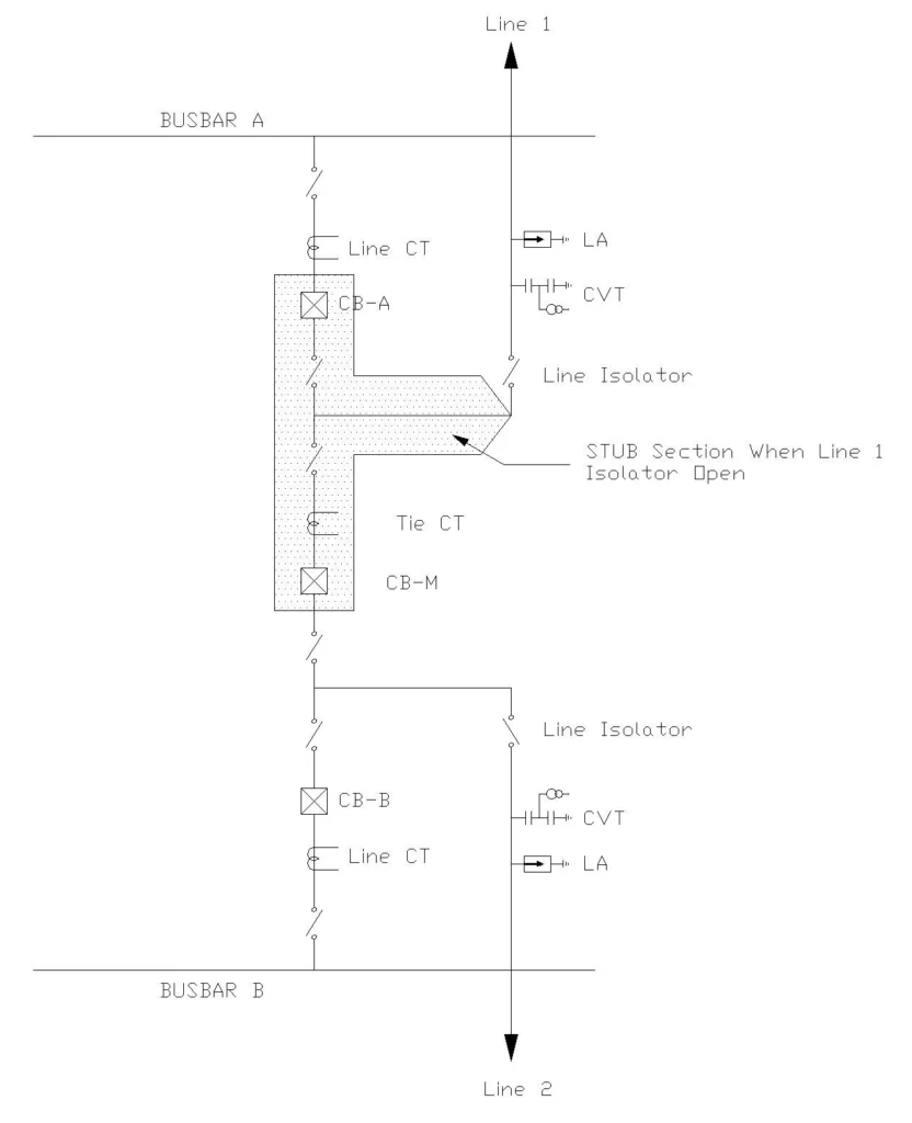
The stub section is energized because all three circuit breakers remain closed, maintaining the electrical continuity from both busbars to the stub section.
Why is the STUB section unprotected by distance protection?
The distance protection relay requires two essential inputs for operation. First, it needs a Current Input (CT – Current Transformer) that provides the current flowing through the line. Second, it requires a Voltage Input (CVT – Capacitive Voltage Transformer) that provides the voltage magnitude and phase reference. The distance relay uses these two inputs to calculate the impedance of the line and determine whether a fault has occurred and approximately where it is located.
When Line 1 is isolated, the CVT secondary voltage becomes zero (there’s no voltage source beyond the line isolator because the transmission line is disconnected from any power source at the isolator point). Without the voltage input, the distance protection relay cannot calculate impedance or determine fault location. The relay becomes blind to faults in the STUB section because it lacks the voltage reference signal.
1.4 Consequence of Stub Faults Without STUB Protection
If a fault occurs in the STUB section without STUB Protection, several dangerous situations can arise. The fault will be fed by current from both Busbar A directly through circuit breaker CBA and also from Busbar B through circuit breaker CBB and the tie breaker CBM, creating parallel fault current paths. Because the distance protection on Line 1 cannot operate (no voltage signal), the fault will persist without being cleared by the line’s primary protection.
However, the distance relay on Line 2 might detect this fault current flowing through circuit breaker CBB and tie breaker CBM as an external fault on Line 2. The Line 2 distance relay could incorrectly trip both the Line 2 breaker (CBB) and the Tie breaker (CBM) after a specific time delay, disconnecting the healthy Line 2 from service. This would cause unnecessary outage and power loss even though Line 2 itself is perfectly healthy.
Meanwhile, the fault in the STUB section would continue to be fed from both Busbar A through the still-closed circuit breaker CBA without being cleared by any protection device, or may eventually be cleared by upstream relays at the source substations. Such scenarios can cause widespread power outages affecting thousands of consumers and critical infrastructure.
2. STUB Protection Fundamentals
2.1 Definition of STUB Protection
STUB Protection is an overcurrent-based protective function that is integrated into distance protection relays and dedicated overcurrent relay modules. It is specifically designed to detect and clear faults occurring in the STUB section of a transmission line when the line isolator is open (line out of service).
When a fault occurs in the STUB zone, this Protection ensures rapid and selective isolation of the faulty section by tripping both the line circuit breaker and the tie circuit breaker without affecting other healthy lines or busbars.
Key Objectives:
- Protect the stub section from short-circuit faults
- Provide rapid fault clearing with minimal delay
- Prevent incorrect tripping of healthy lines and equipment
- Ensure selective operation to isolate only the faulty section
2.2 Type of Protection in STUB Section
STUB Protection is fundamentally different from distance protection in that it relies solely on current measurement without requiring voltage inputs. This overcurrent-based protection scheme is similar to traditional overcurrent relays used in distribution systems.
Why overcurrent-based?
The distance protection algorithm cannot function as the line is de-energized and there is no voltage input to the relay. The only information available to the relay is the fault current flowing through the circuit breakers toward the fault location.
Operating Principle:
The STUB Protection continuously monitors the magnitude of current flowing through the stub section. This is the current supplied from both Busbar A through circuit breaker CBA and the tie breaker CBM, and from Busbar B through circuit breaker CBB. When the measured current exceeds a preset threshold (pickup setting), the protection trips the associated circuit breakers immediately or after a defined time delay, depending on the relay settings.
2.3 STUB Protection Activation Mechanism
STUB Protection is automatically activated when the line isolator opens. This automatic activation is achieved through a binary input signal to the distance relay provided by the auxiliary contact of the line isolator.
When the isolator is opened or closed, a mechanical auxiliary coupled to the isolator also moves changing the auxiliary contact state from NO (normally open) to NC (normally closed) and vice versa. An NC contact is wired to the protection relays digital inputs.
When the isolator is open, this input signal is activated (logical 1), automatically enabling the STUB Protection function in the relay. When the isolator is closed (during normal operation), the input signal is de-activated (logical 0), and STUB Protection is disabled.
3. Technical Details of STUB Protection Operation
3.1 Current Measurement in STUB Protection
STUB Protection monitors the algebraic sum of currents flowing through all the circuit breakers associated with the STUB section. This is essential because the stub fault is fed from multiple sources simultaneously (Both Busbar A and Busbar B), and all these sources must be considered together for reliable fault detection.
Current Combination Principle:
In a one and half breaker scheme, two Current Transformers (CT) are installed: one at each circuit breaker feeding into the busbar and connected to the stub section.
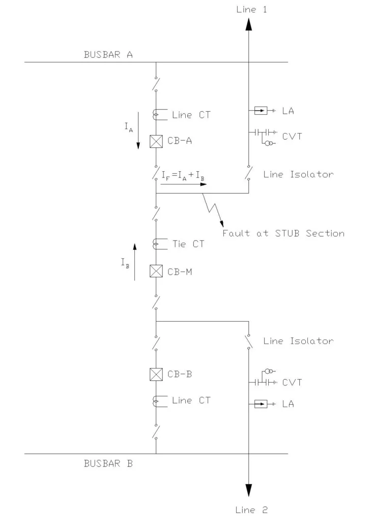
Let is consider a fault occurred at Point A which is in the STUB region is the Line 1 isolator is open. Now current \(I_A\) will flow through the Line circuit breaker (CBA) coming from Busbar A, and current \(I_B\) will flow through the Line Circuit Breaker CBB and Tie circuit breaker (CBM) coming from Busbar B. The combined current \(I_F\) flowing toward the fault into the stub section is represented by the equation:
\(I_F = I_A + I_B\)
When this total current \(I_F\) exceeds the pickup threshold, STUB Protection activates and trips both circuit breakers.
3.2 Fault Detection Threshold
The pickup current is set to a value higher than the maximum normal load current that could flow in the STUB section but lower than the minimum expected fault current.
For transmission lines with STUB Protection, the pickup current is typically set in the range of 1.5 to 2.0 times the maximum load current.
For example, if the maximum load current in the STUB section is 800 amperes, the pickup current might be set between 1200 to 1600 amperes.
3.3 Operating Modes and Time Characteristics
STUB Protection can be configured in different operating modes depending on the relay design and system requirements.
A. Instantaneous Mode:
When STUB Protection is set for instantaneous operation, it trips the circuit breakers immediately (within milliseconds) when the fault current exceeds the pickup threshold, with no intentional time delay. The physical opening of the circuit breaker takes approximately 30-100 milliseconds depending on the breaker design and mechanism.
B. Definite Time Mode:
When configured in definite time mode, STUB Protection introduces a fixed time delay between fault detection and circuit breaker trip command. The relay detects the fault immediately upon the current exceeding the pickup threshold, but then waits for a programmed time (typically 0.1 to 0.5 seconds) before issuing the trip command.
C. Inverse Time Mode:
Some modern relays offer inverse time characteristic where the operating time decreases as the fault current increases. With inverse time characteristics, a very high fault current causes extremely fast tripping, while a lower current takes longer to trip.
3.4 Circuit Breaker Trip Logic
When STUB Protection detects a fault in the stub section, it issues a simultaneous trip command to both the Line Circuit Breaker (CBA) and the Tie Circuit Breaker (CBM). These two breakers must both open at nearly the same time to completely isolate the fault from both busbars.
The simultaneous trip of both breakers is essential because the fault is being fed from both busbars through these two breakers. Opening only the Line Circuit Breaker (CBA) would interrupt the power from Busbar A but would leave the fault still energized and fed from Busbar B through the closed Tie Circuit Breaker (CBM). The fault current would continue to flow, maintaining the arc and causing continued damage.
Similarly, opening only the Tie Circuit Breaker (CBM) would cut off power from Busbar B but would still leave the fault energized from Busbar A through the closed Line Circuit Breaker (CBA). Both breakers must open to completely isolate and clear the fault. The protection logic is programmed to issue the trip command to both breakers simultaneously and they open at nearly the same instant.
4. Configuration and Settings of STUB Protection
4.1 Relay Configuration Requirements
To implement STUB Protection in a protection relay, the following configurations must be established. Each configuration element is crucial for reliable operation and must be verified during commissioning.
A. Binary Input Configuration:
The binary input of the relay must be connected to the auxiliary contact of the line isolator. Signal polarity must be verified to ensure that opening the isolator results in a logical 1 signal that activates STUB Protection.
B. Current Input Configuration:
The CT primary and secondary currents must be correctly configured in the relay’s settings based on the actual CT specifications installed at the substation. The CT burden (load on the CT secondary winding) must be calculated to ensure adequate signal strength and accuracy. The secondary leads must be properly terminated. CT polarity must be verified to ensure both CTs have the same polarity direction, so their currents add correctly rather than subtract.
C. Current Threshold Setting:
The pickup current must be carefully calculated based on a detailed maximum load current analysis for the expected maintenance conditions. The setting must be high enough to avoid false trips during normal load operation, load swings, or transient phenomena. The setting must be low enough to reliably detect the minimum fault current that could occur in the stub section under worst-case conditions.
D. Trip Output Configuration:
The relay must be programmed to trip both the Line Circuit Breaker and the Tie Circuit Breaker simultaneously when a fault is detected. The trip signal outputs must be properly assigned to the correct breaker trip coils. Trip signal timing and sequencing must be verified to ensure both breakers receive the trip command at nearly the same instant.
4.2 Setting Calculation Example
Let’s work through a practical example of STUB Protection setting calculation. This example demonstrates the step-by-step process that protection engineers follow to ensure proper coordination and sensitivity.
A. System Parameters:
Consider a transmission system operating at 220 kV where Line 1 is under maintenance and Line 2 is operating normally. Line 2 carries a maximum load current of 600 A under normal load conditions.
The CT installations use a ratio of 800:5, meaning 800 A of primary current produces 5 A of secondary current in the CT.
B. Pickup Current Calculation:
The allowable fault current is set at 1.8 times the maximum load current. Therefore:
\(\text{Pickup current} = 1.8 × 600 \text{A} = 1080 \text{A primary}\)
Converting to CT secondary:
\(\frac{1080}{800} \times 5 = 6.75 \text{A secondary}\)
Rounding to a practical relay setting value: Selected pickup setting = 6.8 A secondary (equivalent to 1080 A primary).
C. Time Delay Setting:
If instantaneous operation is desired: the time delay setting would be set to 0 seconds (allowing only the relay processing delay of 10-50 milliseconds plus breaker opening time of 30-100 milliseconds for a total clearing time of 40-150 milliseconds).
4.3 Relay Manufacturer Examples
Different relay manufacturers provide STUB Protection with varying nomenclature and configuration options.
A. Siemens SIPROTEC Relays:
Siemens distance protection relays like the 7SA522 and 7SA87 include integrated STUB Protection functionality. The function is called I-STUB (Overcurrent STUB protection). The key inputs and settings include the enable input labeled >I-STUB ENABLE for activation from the isolator auxiliary contact, a block input labeled >BLOCK I-STUB for additional control logic if needed, and configurable settings for pickup current (Is) and time delay (t). The relay logic allows these parameters to be adjusted individually for each line without affecting other protection functions.
B. ABB REL670 Relays:
ABB’s REL670 protection relay includes an optional STUB Protection module that can be enabled for applications where it is needed. The enable condition is typically based on an isolator auxiliary contact signal routed to the appropriate relay binary input. The protection can be configured with either definite time or inverse time characteristics depending on system requirements.
5. STUB Protection vs. Distance Protection Comparison
| Parameter | Distance Protection | STUB Protection |
|---|---|---|
| Activation Condition | Line Isolator CLOSED | Line Isolator OPEN |
| Input Signals Required | CT Input + CVT Input (Current + Voltage) | CT Input ONLY (Current-based) |
| Protection Type | Impedance-based | Overcurrent-based |
| Trip Command | Zone 1, Zone 2, Zone 3 selection | Line CB + Tie CB (simultaneously) |
| Fault Detection Location | Along the entire line length | Stub section only |
| Voltage Requirement | Required (CVT voltage) | NOT required (works without voltage) |
| Clearing Time | Faster (typically 0.02-0.05s) | Very fast (typically 0.01-0.03s) |
| Primary Protection Zone | Complete line from CB to remote end | Stub section between CB and isolator |
6. Commissioning and Testing of STUB Protection
8.1 Pre-commissioning Verification Checklist
Before STUB Protection is placed in service, a verification checklist must be completed to ensure all components are properly installed and configured.
A. Hardware Verification:
- Current Transformers (CTs) are properly connected with correct polarity
- CT secondary winding insulation integrity tested using Megger (minimum 100 MΩ)
- Isolator auxiliary contact mechanism physically inspected for smooth operation
- Wiring continuity verified from isolator aux contact to relay binary input
- Circuit breaker trip coil connections verified for continuity and correct identification
- Relay enclosure earth/ground connection verified according to substation grounding standards
- Backup power supply (UPS or battery) tested for proper operation
B. Settings Verification:
- CT primary and secondary ratios entered correctly in relay configuration
- Pickup current setting calculated and entered according to system study
- Time delay setting configured for proper coordination
- Binary input >I-STUB ENABLE properly configured in relay logic
- Trip output assignments verified that both circuit breakers will receive trip commands
- Relay logic block configuration reviewed and tested
8.2 Functional Testing Procedure
Test 1: Isolator Auxiliary Contact Test
- Step 1: Manually open the line isolator following proper safety procedures
- Step 2: Verify that the auxiliary contact inside or coupled to the isolator changes state (opens or closes depending on design)
- Step 3: Using a multimeter, measure continuity of the signal circuit between the auxiliary contact and the relay binary input
- Step 4: Confirm that the relay’s indication panel or display shows STUB Protection as enabled
- Step 5: Manually close the isolator and verify that the signal returns to its normal state
- Step 6: Confirm that the relay indication shows STUB Protection as disabled
Test 2: Pickup Current Test
- Step 1: With STUB Protection enabled (isolator open and binary input active)
- Step 2: Inject a low primary test current into the CT circuit at 30% of pickup setting using a calibrated test set
- Step 3: Verify that the relay does NOT respond to this low current and remains in normal operating mode
- Step 4: Gradually increase the injection to 50% of pickup setting and verify no response
- Step 5: Further increase to 100% of pickup setting and monitor the relay response
- Step 6: Verify that the relay trips when current reaches the pickup threshold within the time delay window
- Step 7: Record the actual pickup current value (should match the setting within ±3%)
Test 3: Simultaneous Breaker Trip Test
- Step 1: Using a test set, inject current into both CT circuits simultaneously to simulate a fault being fed from both busbars
- Step 2: Adjust the injection to 120% of pickup setting to ensure definite operation
- Step 3: Verify that trip output signals are sent to both the Line Circuit Breaker and Tie Circuit Breaker
- Step 5: Confirm that both trip signals are issued at nearly the same time (within ±5 milliseconds)
- Step 6: Record the timing data
- Step 7: Verify that the relay log contains an entry indicating the trip operation with timestamp
Test 4: Non-operation Test
- Step 1: Close the line isolator to disable STUB Protection
- Step 2: Inject test current into the stub section CT circuit at levels above the pickup setting
- Step 3: Verify that the relay does NOT issue any trip command when STUB Protection is disabled
- Step 4: Confirm that the relay alarm log does not record any protection operation
Conclusion
STUB Protection is an indispensable protective function in modern transmission systems employing the One and Half Breaker scheme. Throughout this technical guide, we have explored how STUB Protection addresses a unique and critical challenge: protecting the stub section between the circuit breaker and the line isolator when a transmission line is taken out of service for maintenance.
By understanding its operating principles, configuration requirements, and practical implementation, electrical engineers can design and maintain reliable protection schemes that ensure power system security and minimize outages.
References and Further Reading
- Siemens SIPROTEC 4, Distance Protection Relay Manual, Edition 05.2016
- IEEE Guide for Protective Relay Applications on Power System Buses (IEEE Std C37.113)
- IEC 60255-151: Measuring Relays and Protection Equipment – Functional Specifications
- Central Electricity Authority, Indian Power Grid Code and Protection Standards
- ABB Protection and Control Products, Technical Documentation
- GE Grid Solutions, Protection Relay Application Guide
- POWERGRID Corporation Limited, Technical Standards and Guidelines
- IEC 61850: Communication Networks and Systems for Power Utility Automation
- IEEE Std C37.112: Guide for Protective Relay Applications of Current Transformers
please in item 1.2 section ( when line 1 is taken out of service )add by opening CB-A and CB-M before the isolator of line 1 is opened because the is taken out of service by opening CB-A and CB-M FRISTLY
Thank you for your valuable suggestion, I have updated the section 1.2 as per your suggestion. Please do check and let me know.