Every transformer generates heat during operation. This heat comes from losses in the core and windings. If the temperature rises beyond safe limits, the insulation material inside the transformer starts to degrade. Over time, this leads to reduced lifespan and even complete failure of the transformer. To prevent this, engineers classify transformers based on the type of insulation used and its ability to withstand heat. These classifications are called temperature classes.
In this technical guide, we will discuss everything you need to know about temperature classes in transformers, including insulation types, temperature rise limits, ANSI codes, hot spot, derating factors, and relevant industry standards. Practical examples are included throughout to help you apply these concepts in real-world scenarios confidently.
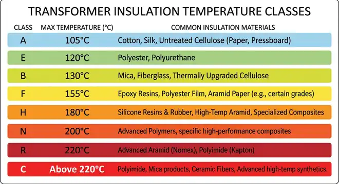
1. What Are Temperature Classes in a Transformer?
A temperature class is a designation given to the insulation system of a transformer based on the maximum operating temperature it can tolerate. The insulation system includes materials like varnish, paper, enamel, mica, and various synthetic compounds used to separate and protect the electrical conductors inside the transformer.
Each insulation material has a thermal limit. If the temperature exceeds that limit for an extended period, the insulation degrades. This degradation is a chemical process. The molecules in the insulation break down, causing the material to become brittle, lose its dielectric strength, and eventually fail. A failed insulation system can lead to short circuits, winding faults, and transformer destruction.
Temperature classes group insulation materials into defined categories. Each category has a maximum temperature rating. The transformer must be designed so that its hottest point does not exceed the temperature limit of the insulation class used in it.
For example, if a transformer uses Class F insulation, the insulation system is rated for a maximum operating temperature of 155°C. The entire thermal design of that transformer including the cooling system, winding configuration, and ambient temperature assumptions must keep the hottest point below 155°C.
2. Standard Temperature Classes and Their Ratings
The most widely used classification system for insulation in transformers follows both ANSI and IEC standards. Below is a table of the standard temperature classes:
| Temperature Class | ANSI/IEC Designation | Maximum Hot Spot Temperature (°C) |
|---|---|---|
| Class A | 105 | 105°C |
| Class B | 130 | 130°C |
| Class F | 155 | 155°C |
| Class H | 180 | 180°C |
| Class N | 200 | 200°C |
| Class R | 220 | 220°C |
| Class S | 240 | 240°C |
| Class C | >220 | Above 220°C |
Class A insulation uses materials like cotton, silk, and paper impregnated with varnish. These are older materials with lower thermal capability. Class B uses materials like mica, fiberglass, and polyester. Class F and Class H use advanced materials such as silicone-based compounds, modified polyester, and high-grade mica composites.
Most modern dry-type transformers use Class F or Class H insulation. Liquid-filled transformers (oil-filled) have their own thermal rating systems but often reference these insulation classes for their winding insulation.
3. How Temperature Rise is Measured in Transformers
Temperature rise in a transformer is the difference between the winding temperature and the ambient temperature. It is not the absolute temperature of the winding. For example, if the ambient temperature is 30°C and the winding temperature is 145°C, the temperature rise is 115°C.
There are three common methods to measure winding temperature:
3.1 Thermometer Method
A thermometer or thermocouple is placed on the surface of the winding. This method only measures surface temperature and does not capture the internal hot spot accurately.
3.2 Resistance Method
This is the most accepted method for dry-type transformers. It measures the change in winding resistance before and after a heat run test. Since resistance increases with temperature, the average winding temperature can be calculated from the resistance change. ANSI/IEEE C57.12.01 requires this method for official temperature rise testing.
3.3 Embedded Temperature Detector (ETD)
A temperature sensor (like an RTD or thermocouple) is embedded inside the winding during manufacturing. This gives a direct reading of the hot spot temperature. This method is common in large power transformers and is used for monitoring during operation.
The hot spot temperature is always higher than the average winding temperature. It occurs at a specific location inside the winding where the heat concentration is highest. The difference between the average winding temperature and the hot spot temperature is called the hot spot allowance or hot spot gradient.
4. The Concept of Hot Spot Temperature
The hot spot is the single warmest point in the transformer winding. It is the most thermally stressed location and it determines the actual life of the insulation. Even if the average winding temperature is within limits, an excessively high hot spot can cause localized insulation failure.
For dry-type transformers, the hot spot allowance is added to the average winding temperature rise to calculate the maximum hot spot temperature. Let us work through an example:
Example:
A dry-type transformer has Class F (155) insulation. The standard ambient temperature is 40°C. The allowable average winding temperature rise is 115°C. The hot spot allowance for this class is approximately 20°C.
- Average winding temperature = 40°C (ambient) + 115°C (rise) = 155°C
- Hot spot temperature = 155°C + 20°C = 175°C
However, the hot spot temperature must not exceed the maximum allowed by the insulation class. For Class F, the absolute maximum hot spot should stay within 155°C for rated insulation life. This is why many manufacturers design transformers with Class F insulation but limit the temperature rise to Class B levels (80°C rise). This practice gives an extra thermal margin and extends insulation life. It is often labeled as “Class F insulation with Class B temperature rise” or “155/B” in transformer specifications.
5. Temperature Class and Insulation Life
The life of transformer insulation follows a well-known thermal aging rule. For every 8°C to 10°C increase in operating temperature above the rated temperature class, the insulation life is approximately cut in half. This relationship is based on the Arrhenius equation, which describes the rate of chemical degradation as a function of temperature.
Here is a simplified illustration:
| Operating Temperature Above Rated Limit | Approximate Effect on Insulation Life |
|---|---|
| At rated temperature | Full expected life (20-30 years) |
| 10°C above rated | Life reduced by approximately 50% |
| 20°C above rated | Life reduced by approximately 75% |
| 30°C above rated | Life reduced by approximately 87.5% |
This means that a transformer with Class F insulation rated for 155°C operating continuously at 165°C would have roughly half the expected insulation life. This is why thermal protection devices, proper ventilation, and correct sizing are so important.
Conversely, operating the transformer below its rated temperature extends insulation life. A Class H transformer operating consistently at Class F temperatures will last much longer than its design life. This is one reason why some engineers specify a higher insulation class than what the temperature rise requires.
6. Dry-Type vs. Liquid-Filled Transformer Temperature Classes
Dry-type and liquid-filled transformers handle heat differently, and their temperature class systems reflect this.
6.1 Dry-Type Transformers
Dry-type transformers rely on air for cooling. They use solid insulation materials like resin, varnish, mica, and fiberglass. The temperature class of a dry-type transformer directly refers to the insulation system used in the windings. Common classes are 130 (B), 155 (F), 180 (H), and 220 (R/N). These are covered under ANSI/IEEE C57.12.01.
Dry-type transformers are commonly installed indoors in commercial buildings, hospitals, data centers, and industrial facilities. Their temperature class is a major selection factor because the ambient temperature inside a building or electrical room can be quite high.
6.2 Liquid-Filled (Oil-Filled) Transformers
Liquid-filled transformers use mineral oil or synthetic fluids for both insulation and cooling. The oil circulates through the windings and carries heat to the external radiators or heat exchangers. The temperature limits for oil-filled transformers are defined differently. ANSI/IEEE C57.12.00 specifies that the average winding temperature rise should not exceed 65°C over a 30°C average ambient (with a maximum ambient of 40°C). The top oil temperature rise is limited to 65°C.
The winding insulation in oil-filled transformers is usually Kraft paper or thermally upgraded paper (TUP). Thermally upgraded paper can withstand higher temperatures and is rated for a hot spot temperature of 110°C. Standard Kraft paper is rated for a hot spot temperature of 95°C.
So, the “temperature class” concept is more directly applied to dry-type transformers, and oil-filled transformers use a different but related thermal rating system.
7. Temperature Class Selection
Selecting the correct temperature class for a transformer involves more than just looking at a datasheet. Several practical factors influence this decision:
7.1 Ambient Temperature
The standard ambient temperature assumed in most standards is 40°C maximum and 30°C average over 24 hours. If the transformer is installed in a location where ambient temperatures regularly exceed 40°C (such as a desert region, a rooftop, or a poorly ventilated room), a higher temperature class should be chosen. Alternatively, the transformer can be derated.
Example: A transformer rated at 1000 kVA with Class F insulation at 40°C ambient may need to be derated to 900 kVA or less if installed in an environment with 50°C ambient temperature.
7.2 Altitude
Air density decreases with altitude. Thinner air is less effective at cooling a dry-type transformer. ANSI standards specify that for installations above 1000 meters (3300 feet), derating or a higher insulation class is needed. For every 500 meters above 1000 meters, the temperature rise capability decreases.
7.3 Loading Profile
A transformer that runs continuously at full load generates more heat than one that operates at partial load or has a cyclical loading pattern. For transformers expected to handle overload conditions frequently, a higher temperature class provides a safety margin.
7.4 Ventilation and Enclosure
Transformers installed in sealed enclosures or poorly ventilated rooms will have higher ambient temperatures around them compared to open-air installations. The temperature class must account for the reduced cooling effectiveness.
7.5 Expected Service Life
If a long service life (30+ years) is desired, selecting a higher temperature class and operating it within the limits of a lower class is a good engineering practice. This “over-insulation” strategy adds thermal margin and slows insulation aging.
8. Derating Transformers Based on Temperature Class
Derating is the process of reducing the rated capacity of a transformer to account for conditions that increase operating temperature. The most common reason for derating is high ambient temperature.
The derating factor depends on the insulation class. ANSI/IEEE C57.96 provides guidance on this topic.
8.1 Example Derating Calculation
A 500 kVA dry-type transformer with Class F insulation (115°C rise) is installed in a room where the ambient temperature reaches 50°C instead of the standard 40°C.
The excess ambient temperature = 50°C – 40°C = 10°C.
The transformer must reduce its load so that the winding temperature rise decreases by 10°C. The relationship between load and temperature rise is approximately:
Temperature Rise ∝ (Load)^1.8
To reduce the temperature rise by 10°C from 115°C:
New allowable rise = 115°C – 10°C = 105°C
Load factor = (105/115)^(1/1.8) ≈ 0.95
Derated capacity = 500 × 0.95 ≈ 475 kVA
This transformer should not carry more than approximately 475 kVA in a 50°C ambient to maintain the thermal integrity of its Class F insulation.
9. Thermal Protection Devices and Temperature Monitoring
To protect transformers from overheating, several thermal protection devices are used. These devices work in conjunction with the temperature class rating to keep the transformer safe.
9.1 Winding Temperature Indicators (WTI):
Winding Temperature Indicators monitor the winding temperature using embedded sensors. They provide alarm and trip signals at preset temperature levels. For a Class F transformer, typical settings might be:
- Alarm: 140°C
- Trip: 155°C
9.2 Thermistors and RTDs
Thermistors (PTC type) and Resistance Temperature Detectors (RTDs) are embedded in the windings during manufacturing. They feed temperature data to a relay or controller that can initiate protective actions like activating cooling fans, sending alarms, or tripping the transformer offline.
9.3 Thermal Overload Relays:
These relays use a thermal model to estimate winding temperature based on the measured load current and ambient conditions. They do not directly measure temperature but infer it from electrical parameters.
9.4 Oil Temperature Indicators (for liquid-filled transformers)
These measure the top oil temperature and provide alarm/trip functions. Common settings are 95°C alarm and 105°C trip for standard mineral oil transformers.
Proper coordination between the temperature class of the insulation and the settings of these protective devices is necessary to prevent damage without causing unnecessary tripping.
10. Practical Example: Specifying a Transformer for a Data Center
Data centers are a good application example because they demand high reliability and long transformer life. Let us walk through a specification scenario.
Application: A 2000 kVA dry-type transformer for a data center.
Location: Indoor electrical room.
Ambient temperature in the room: Expected to be 35°C average, 45°C maximum.
Altitude: 200 meters (below 1000 meters, so no altitude derating needed).
Desired service life: 30 years minimum.
Step 1: Select Insulation Class
Given the high ambient temperature (45°C maximum vs. standard 40°C), there is an extra 5°C of ambient temperature to account for. A Class F insulation system (155°C) with Class B temperature rise (80°C) would be a good choice.
Maximum hot spot temperature = 45°C + 80°C + 30°C (hot spot allowance) = 155°C. This just meets the Class F limit.
However, for a 30-year service life with high reliability, using a Class H insulation system (180°C) with Class F temperature rise (115°C) would be better.
Maximum hot spot temperature = 45°C + 115°C + 20°C = 180°C. This meets the Class H limit with no margin.
Alternatively, use Class H insulation with Class B rise:
Maximum hot spot temperature = 45°C + 80°C + 20°C = 145°C. This is well below the 180°C Class H limit, giving a 35°C thermal margin. This is the best choice for a long-life, high-reliability application.
Step 2: Specify Temperature Monitoring
Include embedded RTDs in the low-voltage and high-voltage windings. Set alarm at 130°C and trip at 150°C. Add forced-air cooling (fans) that activate at 120°C to provide additional cooling during peak loads.
Step 3: Verify Ventilation
Make sure the electrical room has adequate ventilation or air conditioning to keep ambient temperature below 45°C. Calculate the heat dissipation of the transformer at full load (losses in kW) and size the HVAC system accordingly.
This practical example shows how temperature class selection ties directly into overall transformer specification, installation planning, and protection system design.
11. Conclusion
Temperature classes in transformers provide a structured way to classify insulation systems based on their thermal capacity. Each class defines a maximum operating temperature that the insulation can handle over the expected life of the transformer. Standards from ANSI, IEEE, and IEC create a uniform framework for manufacturers and engineers to follow.
Selecting the right temperature class depends on ambient conditions, altitude, loading patterns, ventilation, and desired service life. A common and effective practice is to use a higher insulation class (such as Class F or H) while limiting the temperature rise to a lower class level. This approach adds thermal margin and extends insulation life without major cost increases.
12. Frequently Asked Questions
Class F (155°C) is the most common insulation class used in modern dry-type transformers. Many manufacturers build their transformers with Class F insulation but design the temperature rise to Class B (80°C) levels. This provides an additional thermal margin and extends the life of the insulation.
Operating above the rated temperature class accelerates insulation degradation. For every 8-10°C increase above the rated limit, the insulation life is approximately cut in half. Prolonged operation at excessive temperatures can lead to insulation failure, winding short circuits, and complete transformer failure.
At higher altitudes (above 1000 meters), air is thinner and less effective at cooling dry-type transformers. The transformer must either be derated or use a higher insulation class to compensate.
Temperature rise is the increase in winding temperature above the ambient temperature during operation. Temperature class is the maximum temperature that the insulation system can withstand.
Yes. A Class H transformer can be used anywhere a Class B transformer is specified. It will have a higher insulation rating, which means it will run cooler relative to its insulation limits.
The standard ambient temperature is 40°C maximum and 30°C average over a 24-hour period, as specified in ANSI/IEEE C57.12.00 and C57.12.01.
Check the transformer nameplate. The temperature class is usually listed along with the temperature rise rating. It may appear as a designation like “Class F” or “155°C insulation system” or “115°C rise / 155 insulation.”