A thermostat is the control center of any HVAC system. It tells the heating or cooling equipment when to turn on and when to shut off. Behind this simple function is a wiring system that connects the thermostat to the furnace, air conditioner, heat pump, or other HVAC equipment. A thermostat wiring diagram is a schematic representation of these electrical connections. It shows which wire goes to which terminal and how power flows through the control circuit.
In this technical guide, we will discuss everything you need to know about thermostat wiring diagrams, including terminal designations, wire color codes, circuit configurations for different HVAC systems, heat pump wiring, multi-stage systems, common wiring mistakes, troubleshooting methods, and relevant industry standards. Practical examples are included throughout to help you apply these concepts in real-world scenarios confidently.
1. What Is a Thermostat Wiring Diagram?
A thermostat wiring diagram is a simplified drawing that shows the electrical connections between a thermostat and the HVAC equipment it controls. The diagram uses standard symbols, terminal labels, and color-coded lines to represent the wires and their paths. It does not show the physical layout of the wires. Instead, it focuses on the logical connections between components.
The purpose of this diagram is to guide installers and technicians during installation, replacement, or troubleshooting. Each terminal on the thermostat has a specific letter designation, such as R, W, Y, G, or C. These letters correspond to specific functions in the HVAC system. The diagram maps each wire from the thermostat to the correct terminal on the air handler, furnace, or condenser unit.
Thermostat wiring diagrams can range from simple two-wire configurations for basic heating-only systems to complex multi-wire setups for heat pumps with auxiliary heating and multi-stage cooling. The complexity of the diagram depends on the type of HVAC system.
2. Standard Thermostat Terminal Designations
Every thermostat uses a set of standardized terminal letters. These letters have been adopted across the HVAC industry and are consistent across most thermostat brands. Here is a breakdown of the most common terminal designations:
R (Red) — Power: This terminal receives 24V AC power from the transformer in the HVAC system. It is the main power source for the thermostat control circuit. In some systems, this terminal is split into Rh (power for heating) and Rc (power for cooling).
W (White) — Heating: This terminal connects to the heating system. On a call for heat, the thermostat closes the circuit between R and W, sending 24V to the heating relay or gas valve in the furnace.
Y (Yellow) — Cooling: This terminal connects to the compressor relay in the outdoor condensing unit. On a call for cooling, the thermostat closes the circuit between R and Y.
G (Green) — Fan: This terminal controls the indoor blower fan. It connects to the fan relay on the air handler or furnace. The thermostat energizes this terminal to run the fan independently of heating or cooling.
C (Blue) — Common: This terminal provides the return path for the 24V AC circuit. It connects back to the common side of the transformer. Many modern smart thermostats and WiFi thermostats require a C wire for continuous power.
O/B (Orange/Dark Blue) — Reversing Valve: This terminal is used in heat pump systems. It controls the reversing valve that switches the heat pump between heating mode and cooling mode. The O terminal energizes the valve in cooling mode (used by most manufacturers like Carrier and Trane). The B terminal energizes it in heating mode (used by Rheem and some others).
W2 or AUX — Auxiliary/Emergency Heat: This terminal activates the backup heating source, usually electric resistance heat strips, in a heat pump system. It is used during very cold temperatures when the heat pump alone cannot meet the heating demand.
Y2 — Second Stage Cooling: This terminal connects to the second stage compressor in a two-stage cooling system.
3. Wire Color Codes in Thermostat Wiring
Thermostat wiring uses low-voltage cables, and each wire in the cable has a specific color. The industry follows a general color convention, although it is not enforced by code. Installers should always verify connections at both ends rather than relying solely on color.
Here is the standard color-to-terminal mapping:
| Wire Color | Terminal | Function |
|---|---|---|
| Red | R / Rh / Rc | 24V Power |
| White | W | Heating |
| Yellow | Y | Cooling (Compressor) |
| Green | G | Fan |
| Blue | C | Common |
| Orange | O | Reversing Valve (Cooling) |
| Brown | W2 / AUX | Auxiliary Heat |
| Light Blue or Purple | Y2 | Second Stage Cooling |
Standard thermostat cable comes in bundles of 2, 4, 5, or 8 wires. The most common cable for residential HVAC is an 18-gauge, 5-conductor cable (18/5). If you are installing a smart thermostat that requires a C wire, you will need at least a 5-conductor cable.
Example: A basic heating and cooling system uses a 4-wire cable. The red wire goes to R, white goes to W, yellow goes to Y, and green goes to G. If a WiFi thermostat is being installed, a 5th wire (blue) is added for the C terminal.
4. Basic Thermostat Wiring Diagram: Heating Only (2-Wire System)
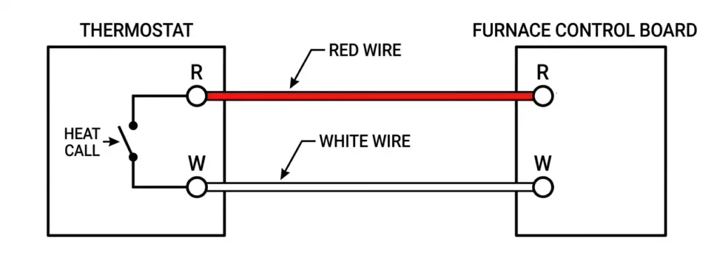
The simplest thermostat wiring diagram is a 2-wire system used for heating-only applications. This setup is common in older homes with a gas furnace or boiler and no central air conditioning.
In this configuration, only two wires connect the thermostat to the furnace:
- Red wire connects to the R terminal on the thermostat and the R terminal on the furnace control board.
- White wire connects to the W terminal on the thermostat and the W terminal on the furnace control board.
The 24V transformer inside the furnace supplies power through the R wire. The thermostat acts as a simple switch. It closes the circuit between R and W to call for heat. This sends 24V to the gas valve or heating relay, and the furnace starts.
There is no fan control wire in this setup because the furnace has its own fan control logic. The blower fan turns on automatically after the heat exchanger reaches a set temperature and turns off after the heat exchanger cools down.
Example: A homeowner has an old mercury thermostat connected to a natural gas furnace with two wires. Replacing it with a basic digital thermostat only requires connecting the red wire to R and the white wire to W on the new thermostat.
5. Standard Thermostat Wiring Diagram: Heating and Cooling (4-Wire and 5-Wire Systems)
Most modern residential HVAC systems use a split system with a furnace (or air handler) and an outdoor air conditioning unit. This requires a minimum of 4 wires and ideally 5 wires.
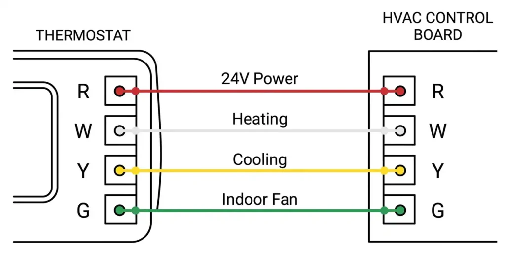
5.1 4-Wire System
A 4-wire thermostat setup uses the following connections:
- R — 24V power from transformer (Red wire)
- W — Heating call (White wire)
- Y — Cooling call / Compressor (Yellow wire)
- G — Indoor fan (Green wire)
The thermostat closes the R-to-W circuit for heating and the R-to-Y circuit for cooling. The G terminal allows the thermostat to run the indoor fan independently for air circulation.
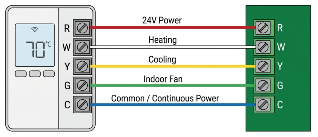
5.2 5-Wire System
A 5-wire system adds the C (common) wire, which is the blue wire. This wire provides a continuous 24V AC power supply to the thermostat. Older mechanical and basic digital thermostats ran on batteries and did not need a C wire. Modern programmable thermostats, WiFi thermostats, and smart thermostats require the C wire for their displays, WiFi radios, and internal processors.
Example: A homeowner upgrades to a Nest or Ecobee smart thermostat. The existing system has only 4 wires. The installer needs to run a new thermostat cable with 5 conductors or use an add-a-wire kit to create a C wire connection.
6. Heat Pump Thermostat Wiring Diagram
Heat pump systems have a more complex thermostat wiring diagram because the same outdoor unit provides both heating and cooling. A reversing valve inside the heat pump switches the direction of refrigerant flow.
A standard heat pump thermostat wiring diagram includes the following connections:
- R — 24V power (Red)
- Y — Compressor (Yellow)
- G — Indoor fan (Green)
- O — Reversing valve, energized in cooling mode (Orange)
- W2 / AUX — Auxiliary heat strips (Brown or White)
- C — Common (Blue)
In heating mode, the thermostat closes the R-to-Y circuit to start the compressor. The reversing valve is de-energized, so the heat pump operates in heating mode. In cooling mode, the thermostat closes both R-to-Y and R-to-O. The reversing valve is energized, switching the system to cooling mode.
If the outdoor temperature drops too low and the heat pump cannot maintain the set temperature, the thermostat activates the W2/AUX terminal. This turns on the electric resistance heat strips inside the air handler to supplement the heat pump output.
6.1 O vs. B Terminal
Most heat pump manufacturers use the O terminal, which energizes the reversing valve in cooling mode. Rheem and a few other brands use the B terminal, which energizes the reversing valve in heating mode. Always check the manufacturer’s documentation before wiring.
7. Multi-Stage Thermostat Wiring Diagram
Multi-stage HVAC systems have two or more stages of heating and/or cooling. These systems improve energy efficiency by running at a lower capacity during mild conditions and ramping up to full capacity only during extreme temperatures.
7.1 Two-Stage Heating
A two-stage furnace has two levels of heat output. The thermostat wiring diagram for this setup includes:
- W1 — First stage heating
- W2 — Second stage heating
The thermostat calls for first-stage heating initially. If the temperature does not reach the setpoint within a set time, the thermostat activates the second stage.
7.2 Two-Stage Cooling
A two-stage air conditioner or heat pump has two compressor speeds. The wiring diagram includes:
- Y1 — First stage cooling
- Y2 — Second stage cooling
The thermostat starts with first-stage cooling and moves to second-stage cooling if needed.
Example: A commercial office building uses a two-stage rooftop unit. The thermostat wiring uses R, C, G, Y1, Y2, W1, and W2. The building management system controls staging based on the difference between the room temperature and the setpoint.
8. The C Wire: Why It Matters for Smart Thermostats
The C wire has become one of the most discussed topics in residential HVAC installation. Older thermostat systems were designed without a C wire because the thermostat only needed a small amount of power, supplied by batteries or by “stealing” power from the R wire during calls for heating or cooling.
Smart thermostats like the Google Nest, Ecobee, and Honeywell Home T9 have processors, touchscreens, and WiFi modules that require a constant 24V power supply. Without a C wire, these devices may not function properly. Symptoms of a missing C wire include short cycling, intermittent WiFi disconnection, and blank thermostat screens.
8.1 Solutions for a Missing C Wire
- Run a new thermostat cable with enough conductors to include a C wire. This is the most reliable solution.
- Use an add-a-wire adapter such as the Venstar ACC0410. This device repurposes one of the existing wires to serve as both the C wire and another function.
- Use a plug-in transformer to power the thermostat externally.
- Use a common wire kit provided by the thermostat manufacturer (e.g., Ecobee includes a Power Extender Kit).
9. Thermostat Wiring and the 24V AC Control Circuit
The thermostat operates on a 24V AC control circuit. This low-voltage circuit is separate from the main power supply (120V or 240V) that runs the furnace blower, compressor, and other high-power components.
A step-down transformer inside the furnace or air handler converts the line voltage (120V AC) to 24V AC. The transformer has two output terminals:
- R (hot) — connects to the R terminal on the thermostat
- C (common) — connects to the C terminal on the thermostat
The thermostat acts as a series of switches. It closes the appropriate circuit between R and the desired function terminal (W, Y, G, etc.). This sends 24V to the corresponding relay or contactor in the HVAC equipment, which then switches on the high-voltage circuit to run the equipment.
Example: A thermostat calls for cooling. It closes the switch between R and Y. 24V flows from the transformer through the R wire to the thermostat, then out through the Y wire to the contactor in the outdoor condensing unit. The contactor closes and sends 240V to the compressor motor. The compressor starts.
This separation of low-voltage control and high-voltage power is a safety feature. It allows the thermostat to be safely installed and serviced without exposure to dangerous voltage levels. The low-voltage thermostat wiring does not require conduit or the same level of protection as line-voltage wiring under the National Electrical Code (NEC), Article 725, Class 2 circuits.
10. Thermostat Wiring Diagram for Dual-Fuel Systems
A dual-fuel system combines a heat pump with a gas furnace. The heat pump handles heating during mild weather. The gas furnace takes over during very cold temperatures. This setup requires a thermostat that supports dual-fuel operation.
The wiring diagram for a dual-fuel system includes:
- R — 24V power
- Y — Heat pump compressor
- O — Reversing valve
- G — Indoor fan
- W2 / AUX — Gas furnace
- C — Common
The thermostat has a changeover temperature setting (also called balance point). Above this temperature, the thermostat calls for the heat pump. Below this temperature, the thermostat switches to the gas furnace by de-energizing the compressor and activating the W2 terminal.
11. Thermostat Wiring in Commercial HVAC Systems
Commercial HVAC systems often use more advanced thermostat wiring configurations. Rooftop units (RTUs), variable air volume (VAV) systems, and chilled water systems may use direct digital controls (DDC) or building automation system (BAS) protocols instead of simple switch-based thermostat wiring.
In commercial systems, the thermostat (or room sensor) may communicate digitally using protocols such as:
- BACnet (ANSI/ASHRAE 135)
- Modbus
- LonWorks
- ZigBee or Z-Wave (for wireless thermostats)
For simpler commercial systems, the wiring diagram follows the same conventions as residential systems but may include additional terminals for economizer control, occupancy sensors, or demand ventilation.
12. Wiring Diagrams for Popular Thermostat Brands
Different thermostat brands may have slightly different terminal layouts, but they all follow the same general conventions. Here is a brief overview:
12.1 Honeywell Home (Resideo)
Honeywell thermostats use standard terminal designations (R, W, Y, G, C, O/B). Their wiring guides are available online for each model. The T6 Pro and T9 models support up to 3 heat / 2 cool stages.
12.2 Ecobee
Ecobee smart thermostats include a Power Extender Kit (PEK) that provides an alternative to running a C wire. The PEK is installed at the furnace control board and repurposes one of the existing wires.
12.3 Google Nest
The Nest thermostat uses non-standard terminal labels in some cases. For example, the Nest uses “*” for the common wire and “OB” for the reversing valve. The Nest Compatibility Checker online tool helps users determine if their existing wiring is compatible.
12.4 Emerson Sensi
The Sensi thermostat uses standard terminal designations. It requires a C wire for WiFi operation. Models like the Sensi Touch support up to 2 heat / 2 cool stages with a heat pump.
13. How to Read a Thermostat Wiring Diagram
Reading a thermostat wiring diagram requires familiarity with a few conventions. Here are the steps:
- Step 1: Identify the thermostat terminals. Look for the labeled terminal strip on the thermostat. Common labels include R, W, Y, G, C, O/B, W2, and Y2.
- Step 2: Identify the equipment terminals. The furnace or air handler control board also has labeled terminals. These labels match the thermostat terminal labels in most cases.
- Step 3: Trace each wire from the thermostat terminal to the equipment terminal. The diagram shows a straight line (or colored line) for each wire. The color of the line matches the wire color.
- Step 4: Verify the transformer connections. The R and C terminals on the equipment connect to the 24V transformer output.
- Step 5: Check for jumpers. Some systems have a jumper between Rh and Rc on the thermostat. This is used in systems where a single transformer powers both heating and cooling. If two transformers are used (one for heating, one for cooling), the jumper is removed.
Example: A technician is replacing a thermostat. Before disconnecting the old thermostat, the technician takes a photo of the wiring. The photo shows: Red wire on R, White wire on W, Yellow wire on Y, Green wire on G, and Blue wire on C. The technician connects the same wires to the same terminals on the new thermostat.
14. Common Thermostat Wiring Mistakes
Incorrect thermostat wiring is one of the most common causes of HVAC system malfunctions. Here are the most frequent mistakes:
14.1 Mixing Up R and C Wires
Reversing the R (power) and C (common) wires can cause a short circuit. This will blow the low-voltage fuse on the furnace control board (usually a 3A or 5A automotive-style fuse).
14.2 Missing the Jumper Between Rh and Rc
If a single transformer powers both the heating and cooling systems, a jumper must connect Rh and Rc on the thermostat. Forgetting this jumper means the thermostat will not have power for one mode (heating or cooling).
14.3 Connecting a Heat Pump to a Conventional Thermostat
Heat pump systems require a thermostat with an O/B terminal. Using a conventional thermostat without this terminal means the reversing valve will not be controlled. The system will not switch between heating and cooling properly.
14.4 Not Labeling Wires During Replacement
Failing to label or photograph the existing wiring before removing the old thermostat makes it difficult to connect the new thermostat correctly. Always document the wiring before disconnecting anything.
14.5 Using the Wrong Wire Gauge
Thermostat wiring should be 18-gauge (AWG) for most residential systems. Longer wire runs may require a heavier gauge to avoid voltage drop. The NEC and manufacturer guidelines specify maximum wire lengths for each gauge.
15. Troubleshooting Thermostat Wiring Problems
Thermostat wiring issues can cause symptoms like no heating, no cooling, fan not running, or a blank thermostat screen. Here is a systematic approach to troubleshooting:
Step 1: Check the Thermostat Display
If the display is blank, check for power. Verify that the 24V transformer is outputting voltage using a multimeter. Measure the voltage between R and C at the thermostat. It should read approximately 24V AC.
Step 2: Check the Fuse
The furnace control board has a low-voltage fuse (usually 3A or 5A). A blown fuse indicates a short circuit in the thermostat wiring. Replace the fuse and inspect the wiring for damaged insulation, pinched wires, or incorrect connections.
Step 3: Test Each Wire
Disconnect the thermostat from the wall. At the furnace control board, use a multimeter to check continuity on each wire between the thermostat location and the furnace. A wire with no continuity is broken or disconnected.
Step 4: Bypass the Thermostat
At the furnace control board, use a short jumper wire to connect R to W (for heating) or R to Y and R to G (for cooling). If the system starts, the thermostat or its wiring is the problem. If the system does not start, the problem is in the HVAC equipment itself.
Example: A homeowner reports that the air conditioner will not turn on. The technician measures 24V at the R and C terminals on the thermostat. The technician then measures the voltage between R and Y at the furnace control board during a call for cooling. If 24V is present at R-Y but the compressor does not start, the problem is the contactor or capacitor in the outdoor unit, not the thermostat wiring.
16. Safety in Thermostat Wiring
Even though thermostat wiring operates at low voltage (24V AC), safety precautions must still be followed:
- Turn off power to the HVAC system at the circuit breaker before working on thermostat wiring. The 24V transformer is powered by a 120V or 240V circuit.
- Verify the power is off using a non-contact voltage tester or multimeter before touching any wires.
- Do not mix low-voltage and line-voltage wiring in the same conduit or junction box unless allowed by NEC Article 725.
- Use plenum-rated cable if the thermostat wire passes through a plenum or return air space.
- Follow manufacturer instructions for both the thermostat and the HVAC equipment.
- Check local codes and permit requirements. Some jurisdictions require a licensed electrician or HVAC technician to perform thermostat wiring work.
17. Conclusion
The thermostat wiring diagram is a fundamental tool for anyone working with HVAC systems. It shows the electrical connections between the thermostat and the HVAC equipment in a clear and standardized format. Each terminal letter, wire color, and circuit path has a specific meaning. Learning these conventions allows you to install new thermostats, replace old ones, and troubleshoot problems efficiently.
The information in this guide applies to most residential and light commercial systems. Always refer to the specific wiring diagram provided with your thermostat and HVAC equipment for the exact terminal designations and connections for your system.
18. Frequently Asked Questions (FAQs)
A thermostat wiring diagram is used to show the electrical connections between a thermostat and the HVAC equipment. It helps installers and technicians connect the correct wires to the correct terminals during installation, replacement, or troubleshooting.
A basic heating-only thermostat needs 2 wires (R and W). A standard heating and cooling thermostat needs 4 to 5 wires (R, W, Y, G, and optionally C). A heat pump thermostat may need 6 to 8 wires, depending on the system configuration.
The C wire is the “common” wire. It provides the return path for the 24V AC control circuit. Modern smart thermostats and WiFi thermostats require a C wire for continuous power.
Some smart thermostats can work without a C wire by using battery backup or power-stealing techniques. However, this can cause reliability issues. It is best to install a C wire or use an adapter kit like the Ecobee Power Extender Kit or a Venstar Add-A-Wire.
Incorrect wiring can cause the HVAC system to malfunction. Common results include the system not turning on, the fan running continuously, or a blown low-voltage fuse on the furnace control board. In some cases, incorrect wiring can damage the thermostat or the HVAC equipment.
Most thermostat wiring uses 18-gauge (18 AWG) wire. This is the standard for residential and light commercial HVAC systems. Longer wire runs may require thicker wire to prevent voltage drop.
The O terminal energizes the reversing valve in cooling mode (used by most manufacturers). The B terminal energizes the reversing valve in heating mode (used by Rheem and a few others). Both control the same valve, but they operate in opposite logic.
Yes. Thermostat wiring is classified as a Class 2 circuit under NEC Article 725. Class 2 circuits have specific requirements for power limits, wire types, and installation methods.
Technically, Cat5 cable can work for thermostat wiring because it uses 24-gauge solid copper conductors. However, 18-gauge thermostat cable is the recommended and standard choice. Cat5 cable may not meet local code requirements for HVAC control wiring.
The wiring diagram is usually printed on the back of the thermostat, inside the thermostat mounting plate, or in the installation manual. Most manufacturers also publish wiring diagrams on their websites.