A Vacuum Circuit Breaker (VCB) is an electrical switching device that uses vacuum as the arc quenching medium. The vacuum inside the interrupter chamber has excellent dielectric properties. This makes it highly effective for interrupting current flow during fault conditions. VCBs are widely used in medium voltage applications ranging from 11 kV to 36 kV.
The technology behind vacuum circuit breakers has evolved over several decades. Today these devices are the preferred choice for power distribution systems in many countries including the United States, United Kingdom, Germany, Australia and India. Their reliability and low maintenance requirements make them popular among electrical utilities and industrial facilities.
1. Construction of Vacuum Circuit Breaker
The vacuum circuit breaker consists of several components that work together to perform switching and protection functions. Each component plays a specific role in the overall operation of the device.
1.1 Vacuum Interrupter (VI)
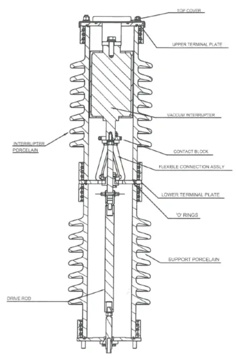
The vacuum interrupter is the heart of the VCB and performs the actual current interruption function. It consists of a sealed ceramic or glass envelope that houses the fixed and moving contacts along with the arc shield. The pressure inside this chamber is maintained at approximately \(10^{-6}\) to \(10^{-8}\) torr. This extremely low pressure creates an ideal environment for arc extinction.
The ceramic envelope provides excellent insulation between the contacts and the external environment. Modern vacuum interrupters use alumina ceramic material that can withstand high temperatures and mechanical stresses. The end plates are made of stainless steel and are brazed to the ceramic body to form a hermetic seal.
1.2 Fixed Contact
The fixed contact is a stationary electrode that remains in one position throughout all switching operations. It is rigidly mounted inside the vacuum interrupter and connects to the external circuit through a terminal. The contact face is made of copper-chromium alloy or copper-bismuth alloy. These materials provide excellent electrical conductivity and high resistance to contact welding during high current operations.
The copper-chromium composition is 75% copper and 25% chromium. This combination offers good arc erosion resistance and low contact resistance. The fixed contact is designed with a specific geometry to promote uniform current distribution across the contact surface.
1.3 Moving Contact
The moving contact is the electrode that travels back and forth to make or break the electrical circuit. It is connected to the operating mechanism through an insulating rod made of epoxy or similar material. When the mechanism operates the moving contact separates from or engages with the fixed contact.
The contact gap between fixed and moving contacts ranges from 5 to 10 mm for medium voltage applications. This small gap is sufficient because vacuum has excellent dielectric strength. The moving contact must travel at high speed during opening operations to quickly establish the arc gap.
1.4 Operating Mechanism
The operating mechanism provides the mechanical force required to open and close the VCB contacts at the required speed. Spring-charged mechanisms are the most common type used in modern VCBs. A motor charges the closing spring and the stored energy is released when the close command is given. The opening spring is charged when the breaker closes. This arrangement allows for fast opening speeds of 1 to 2 meters per second during fault conditions.
Motor-operated and solenoid-operated mechanisms are also available for special applications. The mechanism includes latches that hold the breaker in open or closed position. Trip and close coils receive electrical signals from protection relays to initiate operations.
1.5 Metallic Arc Shield
The metallic arc shield is a cylindrical component that surrounds the contacts inside the vacuum interrupter. During current interruption an arc forms between the separating contacts. This arc produces metal vapor from the contact surfaces due to extreme heat. The arc shield intercepts this metal vapor and prevents it from depositing on the insulating ceramic envelope. Without the arc shield the ceramic surface would become conductive over time and the interrupter would fail.
The shield is made of stainless steel or copper and is positioned between the contacts and the ceramic wall. It also helps in condensing the metal vapor quickly after arc extinction. Some designs use multiple shields for better vapor containment.
1.6 Bellows
The metallic bellows is a flexible component that allows the moving contact to travel while maintaining the vacuum seal inside the interrupter. It is made of thin stainless steel sheets welded together in a corrugated pattern. This design allows the bellows to compress and expand as the moving contact opens and closes.
The bellows must withstand thousands of mechanical operations without developing leaks. A single pinhole in the bellows would destroy the vacuum and render the interrupter useless.
Modern bellows designs can handle 30,000 or more operations over the service life of the VCB.
2. Working Principle of Vacuum Circuit Breaker
2.1 Normal Operating Condition
During normal operation the contacts of the vacuum circuit breaker remain closed. Current flows through the fixed contact, arc shield, moving contact, and then to the external circuit. The vacuum interrupter simply acts as a conductor in this state.
2.2 Fault Condition and Arc Formation
When a fault occurs in the power system the protection relay detects the abnormal current. It sends a trip signal to the operating mechanism of the VCB. The mechanism releases stored energy and the moving contact separates from the fixed contact rapidly.
As the contacts separate an electric arc forms between them. This arc is a plasma channel through which current continues to flow. The arc temperature can reach up to 20,000 Kelvin at the contact surface. Metal vapor is released from the contact surface due to this extreme heat.
2.3 Arc Extinction Process
The arc extinction in a vacuum circuit breaker follows a unique process. When the contacts part the arc burns in metal vapor released from the contact surfaces. Since there is no gas or oil in the chamber this metal vapor is the only conducting medium.
The metal vapor condenses on the metallic arc shield and contact surfaces as the current approaches zero. At current zero the vapor density between the contacts reduces rapidly. The dielectric strength of the gap recovers very quickly because vacuum has excellent insulating properties.
The recovery of dielectric strength in vacuum is about 1000 times faster than in air or oil. This makes VCBs extremely effective at preventing arc re-ignition after current zero. The entire arc extinction process happens within a few milliseconds.
Consider a VCB installed in an 11 kV power distribution substation. A short circuit occurs in one of the outgoing feeders. The protection relay detects this fault current of 25 kA and sends a trip command to the VCB. The operating mechanism opens the contacts within 30 milliseconds. The arc burns for about 10 milliseconds and extinguishes at the first or second current zero. The total fault clearing time is approximately 40 to 50 milliseconds.
3. Types of Vacuum Circuit Breakers
3.1 Based on Installation
Indoor VCB: These are designed for installation inside buildings or switchgear rooms. Indoor VCBs have an IP rating suitable for protected environments. They are commonly used in substations and industrial facilities.
Outdoor VCB: These units come with weatherproof enclosures for outdoor installation. They can withstand rain, dust, and temperature variations. Outdoor VCBs are used in pole-mounted applications and outdoor substations.
3.2 Based on Operating Mechanism
Spring Operated VCB: The most common type that uses charged springs for closing and opening operations. An electric motor charges the closing spring. This type offers reliable operation and can perform multiple operations without external power.
Magnetic Actuator VCB: Uses electromagnetic force for contact operation. It has fewer mechanical parts compared to spring mechanisms. This type offers faster operation and requires less maintenance.
Motor Operated VCB: Uses an electric motor directly coupled to the operating shaft. This type is used in special applications where precise control is required.
4. Advantages of Vacuum Circuit Breaker
4.1 Long Service Life
Vacuum circuit breakers have an extended operational life compared to other types of circuit breakers. They can perform 10,000 to 30,000 switching operations without major maintenance. The sealed vacuum interrupter protects internal components from environmental contamination. This results in consistent performance over many years of service.
4.2 Low Maintenance Requirements
VCBs require minimal maintenance during their operational life. There is no oil to replace or gas to refill. The sealed interrupter eliminates the need for regular contact inspection. Maintenance intervals can extend to 10 years or more in normal operating conditions.
4.3 Compact Design
The excellent arc quenching properties of vacuum allow for smaller contact gaps. This results in a compact overall design that saves space in switchgear panels. A 12 kV VCB is much smaller than an equivalent oil circuit breaker. This compact size reduces installation costs and floor space requirements.
4.4 Environmental Friendliness
Vacuum circuit breakers do not contain oil or SF6 gas. They do not pose environmental hazards in case of failure. There are no greenhouse gas emissions associated with their operation. VCBs are considered the most environmentally friendly option for medium voltage switching.
4.5 Fast Operation
VCBs can interrupt fault currents within 2 to 3 cycles of the power frequency. The fast dielectric recovery of vacuum enables quick arc extinction. This rapid operation limits damage to power system equipment during faults.
4.6 Silent Operation
Unlike oil or air blast circuit breakers VCBs operate quietly. There is no loud noise during switching operations. This makes them suitable for installation in noise-sensitive areas like hospitals and residential neighborhoods.
4.7 No Fire Hazard
Since VCBs do not use oil there is no risk of fire or explosion. This is a major safety advantage in industrial facilities. VCBs are preferred in locations where fire safety is a priority.
5. Disadvantages of Vacuum Circuit Breaker
5.1 Higher Initial Cost
The initial purchase cost of VCBs is higher than oil circuit breakers. The vacuum interrupter manufacturing requires specialized technology. However the lower maintenance costs offset this higher initial investment over time.
5.2 Voltage Limitations
VCBs are most effective in the medium voltage range. For voltages above 36 kV the design becomes complex and expensive. Multiple interrupters must be connected in series for higher voltages. This makes SF6 circuit breakers more practical for high voltage applications.
5.3 Contact Erosion
During high current interruption the contact surfaces erode due to arcing. This erosion can affect the performance after many operations. The contacts must be replaced after a certain number of fault current interruptions.
5.4 Overvoltage Generation
VCBs can produce switching overvoltages during current chopping. Current chopping occurs when the circuit breaker forces the current to zero before its natural zero crossing. This can create voltage spikes that may damage connected equipment like transformers and motors.
5.5 Vacuum Integrity
If the vacuum seal fails the interrupter loses its interrupting capability. A loss of vacuum cannot be easily detected without special testing equipment. Regular vacuum integrity tests are recommended for older VCBs.
6. Applications of Vacuum Circuit Breaker
- Power Distribution Systems: VCBs are extensively used in 11 kV and 33 kV distribution substations. They serve as incoming and outgoing feeders in substations. Electrical utilities prefer VCBs for their reliability in distribution networks.
- Industrial Plants: Manufacturing facilities use VCBs to protect motors and transformers. Chemical plants and refineries prefer VCBs due to their fire-safe operation. Steel mills and cement plants use VCBs for heavy-duty switching applications.
- Commercial Buildings: Large commercial complexes install VCBs in their electrical rooms. Shopping malls and office towers use VCBs for their main power distribution.
- Mining Industry: Underground mines require circuit breakers with no fire risk. VCBs are ideal for these applications due to their oil-free design. They can withstand dusty and humid conditions in mining environments.
- Railway Electrification: VCBs are used in traction substations for railway systems. They handle the switching of power supply to electrified rail lines. Their fast operation protects sensitive electronic equipment on modern trains.
- Renewable Energy: Solar power plants and wind farms use VCBs in their collection systems. VCBs connect and disconnect solar inverters and wind turbines from the grid.
7. Comparison with Other Circuit Breakers
7.1 VCB vs Oil Circuit Breaker (OCB)
Oil circuit breakers use mineral oil as the arc quenching medium. They require regular oil testing and replacement. OCBs pose fire risks due to oil flammability. VCBs are safer and require less maintenance than OCBs.
7.2 VCB vs SF6 Circuit Breaker
SF6 circuit breakers use sulfur hexafluoride gas for arc extinction. They are preferred for voltages above 72.5 kV. SF6 is a potent greenhouse gas with high global warming potential. VCBs are more environmentally friendly for medium voltage applications.
7.3 VCB vs Air Circuit Breaker (ACB)
Air circuit breakers operate in atmospheric air. They are commonly used for low voltage applications below 1 kV. VCBs are more suitable for medium voltage applications. ACBs are larger in size compared to VCBs for the same ratings.
7.4 Comparison Table
| Feature | VCB | OCB | SF6 CB | ACB |
|---|---|---|---|---|
| Arc Quenching Medium | Vacuum | Oil | SF6 Gas | Air |
| Voltage Range | 3.3-36 kV | 3.3-220 kV | 3.3-800 kV | Up to 6.6 kV |
| Maintenance | Very Low | High | Low | Medium |
| Fire Risk | None | High | None | None |
| Environmental Impact | None | Oil Disposal | High GWP | None |
| Size | Compact | Large | Medium | Large |
8. Maintenance of Vacuum Circuit Breaker
8.1 Periodic Inspection
Visual inspection should be performed at regular intervals. Check for any physical damage to the enclosure or bushings. Verify that indicators show correct positions. Look for signs of overheating at connection points.
8.2 Insulation Testing
Measure insulation resistance using a 2500 V megger. Compare results with previous measurements and manufacturer specifications. A sudden decrease in insulation resistance indicates a problem. Clean insulating surfaces if resistance values are below acceptable limits.
8.3 Contact Resistance Testing
Measure the resistance across closed contacts using a micro-ohmmeter. High contact resistance indicates worn contacts or poor connection. Contact resistance should be within the range specified by the manufacturer. This test should be performed after every maintenance outage.
8.4 Mechanism Inspection
Check the operating mechanism for proper operation. Verify that spring charging motor operates correctly. Lubricate moving parts as recommended by the manufacturer. Test manual and electrical operation of the circuit breaker.
8.5 Timing Tests
Measure opening and closing times using a timing analyzer. Compare results with factory test values. Abnormal timing may indicate mechanism problems. Timing tests should be performed after any major maintenance work.
8.6 Vacuum Integrity Check
The vacuum level can be checked indirectly using a DC withstand test. Apply 80% of rated power frequency withstand voltage as DC. If the interrupter fails this test the vacuum may have deteriorated. This test should be performed on VCBs older than 15 years.
9. Standards and Ratings for VCB
9.1 International Standards
VCBs must comply with applicable international standards. IEC 62271-100 covers high-voltage switchgear and circuit breakers. IEEE C37 series provides standards for circuit breakers in North America. These standards specify performance requirements and testing procedures.
9.2 Voltage Ratings
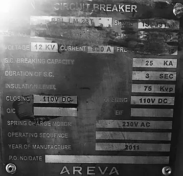
Rated voltage indicates the maximum system voltage the VCB can handle. Standard rated voltages include 12 kV, 17.5 kV, 24 kV, and 36 kV. The rated voltage must be equal to or higher than the system voltage.
9.3 Current Ratings
Rated normal current is the continuous current carrying capacity. Standard values include 630 A, 1250 A, 2000 A, 2500 A, and 4000 A. The rated short circuit breaking current indicates fault clearing capability.
9.4 Making and Breaking Capacity
The making capacity is the maximum current the VCB can close onto. It is usually 2.5 times the rated short circuit current. The breaking capacity is the maximum fault current the VCB can interrupt. These ratings must exceed the maximum fault levels in the system.
10. Conclusion
Vacuum Circuit Breakers have become the preferred choice for medium voltage power distribution systems across the world. Their ability to extinguish arcs quickly in a vacuum environment makes them highly reliable for protecting electrical networks. The simple construction with fewer components results in lower maintenance requirements compared to oil and SF6 circuit breakers.
11. Frequently Asked Questions (FAQs)
A Vacuum Circuit Breaker is an electrical switching device that uses vacuum as the medium for arc extinction. It operates in the medium voltage range of 3.3 kV to 36 kV and is widely used in power distribution systems.
When the contacts separate an arc forms in the metal vapor released from the contact surfaces. As the current approaches zero the metal vapor condenses rapidly. The high dielectric strength of vacuum prevents arc re-ignition after current zero.
The pressure inside a vacuum interrupter is maintained at approximately 10^-6 to 10^-8 torr. This extremely low pressure creates the vacuum environment needed for effective arc extinction.
The contact gap in a VCB is typically 5 to 10 mm for medium voltage applications. This small gap is possible due to the excellent dielectric properties of vacuum.
VCBs are preferred because they require less maintenance, have no fire risk, and are more compact. They do not require oil testing or replacement and have a longer service life.
Vacuum integrity can be checked using a DC withstand test at 80% of rated power frequency withstand voltage. X-ray methods can also detect partial loss of vacuum.