Winding resistance measurement is a fundamental diagnostic test performed on power transformers during commissioning and routine maintenance. This test assesses the electrical integrity of transformer windings and detects hidden faults. The DC winding resistance test identifies problems such as loose connections, broken conductor strands, and deteriorated tap changer contacts. If left undetected, these faults can lead to transformer failure and costly power outages.
In this technical guide, we will discuss everything you need to know about the winding resistance test of power transformers, including its working principle, test procedures, equipment requirements, acceptance criteria, temperature correction formulas, and relevant industry standards. Practical examples are included throughout to help you apply these concepts in real-world scenarios confidently.
1. What is Winding Resistance?
The winding resistance definition in its simplest form is the ohmic (DC) resistance of a transformer’s primary and secondary windings. It is the opposition offered to direct current flow through the conductor material. Several factors influence the winding resistance of a transformer. These include the type of conductor material (copper or aluminum), the cross-sectional area of the conductors, the total length of the winding turns, the condition of all internal connections, and the physical integrity of the conductor itself.
The measurement of winding resistance follows a straightforward method. A known DC current is injected through the winding under test, and the voltage drop across the terminals is recorded. The resistance is then calculated using Ohm’s Law:
\(R = \dfrac{V}{I}\)
1.1 Why DC is used for Winding Resistance Test not AC?
DC current is used for this test instead of AC current. The reason is simple. An AC measurement on a transformer winding produces an impedance reading, not a pure resistance reading. The large inductance of the winding creates an inductive reactance \((X_L = 2\pi f L)\) that is far greater than the resistive component at power frequency. This makes it impossible to accurately extract the true ohmic resistance from an AC measurement. DC current eliminates inductive reactance entirely and provides a clean and accurate winding resistance measurement once the reading stabilizes.
2. Why is the Winding Resistance Test Important?
The winding resistance test serves multiple important purposes in transformer diagnostics.
First, the test detects internal winding faults that cannot be observed through visual inspection alone. These include broken conductor strands, loose connections, poor brazing or crimping of internal joints, and high-resistance contacts.
Second, the test provides baseline measurement data for future trending during maintenance cycles. Engineers can track changes in transformer winding resistance values over time.
Third, the winding resistance test verifies that all winding connections are secure and properly assembled according to design specifications. This verification is important during pre-commissioning of new transformers and after any internal repairs or rewinding.
Fourth, the test can reveal problems in on-load tap changers (OLTCs) and de-energized tap changers (DETCs). Measuring resistance across different tap positions helps identify contact degradation, excessive wear, or carbon deposits on switching contacts.
2. Equipment Required for Transformer Winding Resistance Measurement
2.1 DC Winding Resistance Tester
Use a dedicated instrument with automatic measurement capability and a built-in discharge circuit. A compliance voltage above 40 VDC is preferred for faster stabilization on large transformers. Modern transformer winding resistance testers combine the DC source, ammeter, voltmeter, and discharge circuit in a single instrument.
2.2 Temperature measurement device
A temperature probe or infrared thermometer is needed to record the winding temperature accurately for temperature correction calculations.
2.3 Analog multimeter
This is used for continuity checks during tap changing operations. An analog meter is preferred over a digital meter because its needle provides continuous real-time indication. Any momentary break in the circuit during tap changing is immediately visible as a needle deflection. A digital display might miss this due to its slower update rate.
2.4 Test leads and cables
Use leads with proper insulation ratings. The leads must support 4-wire Kelvin connections for accurate low-resistance measurement.
3. Pre-Test Requirements
Before starting the measurement of winding resistance, complete the following preparations:
Isolate and de-energize the transformer completely. Allow adequate time for the transformer to cool to ambient temperature. Visually inspect all winding terminals and tap changer contacts for cleanliness, corrosion, or mechanical damage. Verify that all bolted connections are tight and secure.
Ground the transformer tank and all winding terminals not under test. Short-circuit all terminals of the winding not under test and connect them to ground. This is an important step that many field engineers overlook. Shorting the non-tested winding terminals reduces the effective L/R time constant of the test circuit. This reduces the stabilization time — on large power transformers, this step alone can reduce the wait time from 15–30 minutes down to just a few minutes.
Record the ambient temperature and oil temperature (if applicable) before testing begins.
4. Selection of Appropriate Test Current
Test current selection directly affects the accuracy and efficiency of the transformer resistance test. According to the winding resistance test standard IEEE C57.152 and IEC 60076, the DC test current should follow these guidelines:
- Current range: The test current should fall between 0.1% and 10% of the winding’s rated current. This range provides enough current for accurate measurement without causing unwanted heating.
- Minimum current: Use at least 1 ampere for HV windings. A range of 1–3 A is common for standard HV winding testing.
- Maximum current: Do not exceed 10% of the winding’s rated current. For LV windings with very high current ratings, currents up to 5% of rated current are sufficient.
4.1 Practical Selection Guidelines
For high-resistance windings (above 100 mΩ), use 10 A or less. For low-resistance windings (below 100 mΩ), use 20–50 A for improved measurement accuracy. Always select the highest current available within the 10% limit. This minimizes measurement uncertainty and reduces stabilization time.
Example: A transformer with a rated HV current of 100 A should be tested with a DC current not exceeding 10 A (10% of 100 A). A practical choice would be 5–10 A.
5. Standard Test Procedures for Winding Resistance Measurement
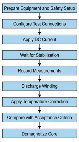
5.1 Step 1: Configure Test Connections
The test connections depend on the winding configuration. The three most common configurations are star (wye), delta, and auto-transformer connections.
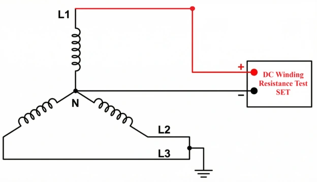
5.1.1 For Star (Wye) Connected Windings
Measure resistance between each line terminal and the neutral terminal. The required connections are L1 to N (or H1 to H0), L2 to N (or H2 to H0), and L3 to N (or H3 to H0). This gives three individual phase resistance measurements that can be directly compared against each other.
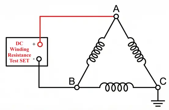
5.1.2 For Delta Connected Windings
Measure resistance between pairs of line terminals. The required connections are A to B (or H1 to H2), B to C (or H2 to H3), and C to A (or H3 to H1).
In a delta configuration, each line-to-line measurement sees one winding in parallel with the other two windings in series. For balanced windings where all three phase resistances are equal, the individual winding resistance can be calculated using the winding resistance test of transformer formula:
Resistance per winding = 1.5 × Measured line-to-line value
5.1.3 For Auto-Transformer Windings
For star-connected auto-transformers, measure resistance between the HV terminal and the IV (Intermediate Voltage, also called the LV or common) terminal. Then take a second measurement between the IV terminal and the neutral point.
For delta-connected tertiary windings, measure between pairs of line terminals using the same method as standard delta connections.
5.2 Step 2: Establish Test Connections
Connect the current source leads to the winding terminals being tested. Connect the voltage measurement leads beyond (outside of) the current leads at the same terminals. This arrangement is called the 4-wire Kelvin method, and it eliminates the resistance of the test leads and contact resistance at the test clamps from the measurement. All accurate low-resistance measurements require this technique.
Short-circuit all terminals of the winding not under test and connect them to ground. As explained in the preparation section, this step reduces the effective inductance seen by the test circuit and greatly reduces stabilization time.
Ground the transformer tank and core to earth.
5.3 Step 3: Apply DC Current and Allow Stabilization
Apply the selected test current and wait for the reading to stabilize. Do not record any readings until the displayed value has remained constant. The initial transient period occurs because the winding’s inductance opposes the sudden change in current. The DC current creates a growing magnetic field in the transformer core, and the resistance reading will appear to “drift” upward or downward until the core approaches magnetic saturation. Only after the current reaches its true steady-state value does the meter display the actual DC winding resistance.
For small distribution transformers, stabilization takes only a few seconds. For large power transformers (50 MVA and above), stabilization may take several minutes or even longer than 10 minutes. Delta-connected windings generally take longer than star-connected windings due to their higher effective inductance.
5.4 Step 4: Record Measurements
After the readings have stabilized, record the resistance value displayed by the test equipment (or record the voltage and current values if using a manual calculation method).
Note the exact winding temperature at the moment of measurement. Record all readings in a test log with the date, time, transformer identification, tap position, and test conditions. Take at least two measurements per winding to verify consistency. If results vary by more than 1% between repetitions, investigate connection problems before proceeding.
Before moving to the next winding or changing the tap position, fully discharge the winding using the test equipment’s built-in discharge function. Wait for the discharge indicator to confirm that discharge is complete. Never disconnect or reconnect any leads until the discharge process is finished. Failure to discharge the winding properly can result in a dangerous voltage spike.
5.5 Step 5: Temperature Correction to Standard Reference Temperature
All field measurements must be corrected to a standard reference temperature for comparison with factory test data and for diagnostic trending. The most commonly used reference temperature is 75°C. Some transformer specifications use 85°C or 20°C as the reference temperature. Always check the factory test report to confirm the reference temperature that was used before applying corrections.
The winding resistance temperature correction formula for copper windings is:
\(R_{75}=R_t\times \dfrac{(234.5+75)}{(234.5+t)}\)
For aluminum windings, replace 234.5 with 225:
\(R_{75}=R_t\times \dfrac{(225+75)}{(225+t)}\)
Where:
- \(R_{75}\) = Resistance corrected to 75°C (in ohms)
- \(R_t\) = Resistance measured at the actual winding temperature (in ohms)
- \(t\) = Actual measured winding temperature during the test (in °C)
- \(234.5\) = Inferred zero-resistance temperature constant for copper conductors
- \(225\) = Inferred zero-resistance temperature constant for aluminum conductors
5.5.1 Example Calculation — How to Calculate Winding Resistance of Transformer at 75°C:
Suppose a copper winding measures 0.0394 ohms at an oil temperature of 26°C. To calculate the transformer winding resistance value corrected to 75°C:
\(R_{75}=0.0394\times \dfrac{(234.5+75)}{(234.5+26)}\)
\(R_{75}=0.0394\times \dfrac{309.5}{260.5}\)
\(R_{75}=0.0394\times 1.188\)
\(R_{75}=0.0468 \text{ohms}\)
This corrected value of 0.0468 ohms is the number you compare against the factory test value and previous field test data. Without this temperature correction, field measurements taken at different ambient temperatures cannot be meaningfully compared.
5.6 Step 6: Compare Results Against Acceptance Criteria
The transformer winding resistance test acceptance criteria are based on guidelines from IEEE C57.152 and IEC 60076. The following limits apply:
Comparison between phases: Resistance values of all three phases should be within 1% of each other at the same tap position. A variation exceeding this limit indicates a possible problem on the affected phase such as a loose connection or broken conductor strand.
Comparison with factory test value: Field measurements, after temperature correction to the same reference temperature, should be within 5% of the original factory test value. This 5% tolerance accounts for differences between field and laboratory measurement conditions.
Comparison with previous field measurements: Changes exceeding 2% from the last field test result indicate winding deterioration or connection problems that require further investigation.
Measurement across tap positions: For transformers with on-load tap changers (OLTC), the winding resistance should show a smooth and consistent progression across all tap positions. Sudden jumps or discontinuities indicate tap changer contact degradation.
The specific acceptance criteria may vary depending on the transformer manufacturer’s specifications. Always review the project-specific test procedures and compare against the standards applicable to your installation.
6. Testing Across Multiple Tap Positions
For transformers equipped with on-load tap changers (OLTC), the winding resistance test on transformer is performed across all tap positions to assess the condition of the tap changer contacts. This test is one of the most effective methods for detecting OLTC problems.
The standard procedure involves measuring winding resistance at every tap position from the minimum to the maximum. Common OLTC designs have 17, 19, 21, or 33 positions — refer to the transformer nameplate for the exact number. After reaching the maximum position, measure in the reverse direction back to the minimum. For efficiency, you may test only 2–3 intermediate positions during the reverse sweep.
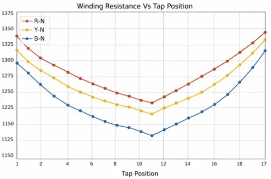
Plot the resistance values across all tap positions on a graph for analysis. A smooth and continuous resistance curve across all positions indicates healthy tap changer operation. Sharp spikes or discontinuities at certain positions indicate contact problems, excessive wear, or carbon deposits on switching contacts.
Compare the resistance-versus-tap-position curves of all three phases on the same graph. If one phase shows abnormal spikes or a distinctly different pattern compared to the other two phases, it indicates phase-selective contact degradation in the OLTC mechanism.
During tap changing operations, use an analog multimeter connected between the HV and neutral terminals to perform continuity checks. The continuity should be maintained without interruption throughout the entire switching sequence. Any momentary loss of continuity during switching indicates a break-before-make contact problem, which is a serious concern for the OLTC mechanism.
7. Core Demagnetization After Testing
The DC winding resistance test must be performed last, after completion of all other low-voltage tests on the transformer. The DC current injection required for core saturation leaves the transformer core with residual magnetization. If the core is not properly demagnetized before energizing the transformer, the residual magnetization can cause several problems.
These problems include inrush currents much higher than normal (with the risk of tripping protective relays), harmonic distortion in the transformer’s magnetizing current, inaccurate results on subsequent electrical tests such as magnetizing current and magnetic balance tests, and possible damage to sensitive protective relays or metering equipment connected to the transformer.
7.1 Demagnetization Procedure
After completing all winding resistance measurements, apply a decreasing AC voltage at power frequency (50 Hz or 60 Hz) to the transformer winding. Start with a voltage slightly higher than the normal operating voltage. Gradually reduce the AC voltage amplitude in small steps of about 5–10% per step. Maintain each voltage level for several complete cycles before reducing further. Continue this process over many cycles until the voltage reaches zero. At zero voltage, the residual magnetization is effectively eliminated.
The entire demagnetization process may take several minutes depending on the transformer size. Most modern transformer winding resistance testers include an automatic demagnetization function that handles this procedure electronically. After demagnetization, verify success by checking that magnetizing current measurements return to their expected values.
8. Interpretation of Test Results
8.1 Normal Results
Normal transformer winding resistance test values show the following characteristics:
All three phase resistances should be within 1% of each other. Temperature-corrected values should be within 5% of the factory test data. For OLTC transformers, the resistance-versus-tap-position graph should show a smooth progression with no sudden jumps or discontinuities. After stabilization, the readings should remain steady without observable drift over 60 seconds.
8.2 Abnormal Results Indicating Winding Problems
Loose connections or broken strands appear as higher than normal resistance in one or more phases. The phase-to-phase resistance variation may exceed 2–3%. You may also see an abrupt increase in resistance compared to the factory baseline or previous field measurements.
Tap changer contact deterioration appears as variable resistance across tap positions in OLTC transformers. Sharp resistance spikes at certain tap positions indicate arcing or contact erosion. Asymmetric curves where one phase shows a distinctly different resistance pattern compared to the other two phases are another strong indicator.
Internal conductor damage appears as gradually increasing resistance over multiple maintenance test cycles. Phase imbalance that was not present during factory testing or earlier field tests is another sign. Higher resistance that does not improve after retightening external connections suggests the problem is located inside the transformer.
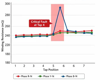
Here is an example table showing Abnormal Winding Resistance Results for a 7-tap distribution transformer.
In this scenario, Phase B (Blue) shows a fault at Tap Position 4, while Phases R and Y show normal.
| Tap Position | Phase R-N (mΩ) | Phase Y-N (mΩ) | Phase B-N (mΩ) | % Deviation (Phase-to-Phase) | Status |
|---|---|---|---|---|---|
| 1 | 200.1 | 200.2 | 200.5 | 0.20% | Normal |
| 2 | 210.3 | 210.1 | 210.4 | 0.14% | Normal |
| 3 | 220.2 | 220.4 | 220.3 | 0.09% | Normal |
| 4 | 230.1 | 230.2 | 285.5 | 24.0% | CRITICAL FAULT |
| 5 | 240.2 | 240.3 | 240.4 | 0.08% | Normal |
| 6 | 250.1 | 250.2 | 250.3 | 0.08% | Normal |
| 7 | 260.3 | 260.1 | 260.4 | 0.11% | Normal |
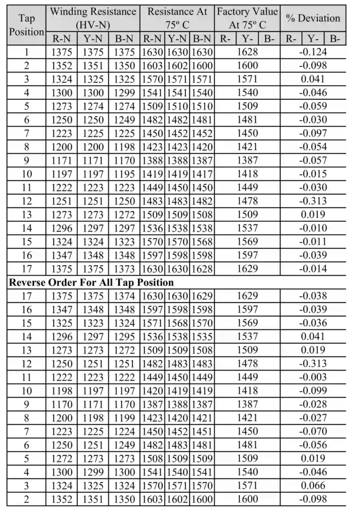
8.3 Transformer Winding Resistance Real Field Test Data Example
The table below shows the actual winding resistance test results I recorded during the pre-commissioning of a 20 MVA, 132/33 kV power transformer. The test covers the HV winding (R-N, Y-N, B-N) across all 17 tap positions.
Notice that measurements were taken in both forward and reverse orders to validate the mechanical integrity of the On-Load Tap Changer (OLTC). The measured values were corrected to the standard reference temperature of 75°C. As shown in the last column, the deviation between field results and factory values is consistently below 0.35%, far superior to the permissible limit. This confirms that the winding connections and tap changer contacts are in excellent condition.
10. Applicable Standards for Winding Resistance Testing
Several industry standards govern the transformer winding resistance test procedure and its acceptance limits. The main standards include:
- IEEE C57.152 — IEEE Guide for Diagnostic Field Testing of Fluid-Filled Power Transformers, Regulators, and Reactors
- ANSI/IEEE C57.12.90 — IEEE Standard Test Code for Liquid-Immersed Distribution, Power, and Regulating Transformers
- IEC 60076-1 — Power Transformers – Part 1: General (includes winding resistance test standard requirements)
- ANSI/NETA MTS — Standard for Maintenance Testing Specifications for Electrical Power Equipment
These standards provide guidelines on test current selection, temperature correction methods, and the transformer winding resistance test acceptance criteria used to evaluate results. Always refer to the applicable standard and the transformer manufacturer’s specifications for the specific project.
11. Transformer Winding Resistance Temperature Correction Calculator
12. Conclusion
The winding resistance test is one of the most important diagnostic procedures in power transformer commissioning and preventive maintenance. This simple yet powerful test can reveal hidden problems such as loose connections, broken conductor strands, and deteriorated tap changer contacts long before they cause service failures. Following the correct transformer winding resistance test procedure, selecting appropriate test currents, and applying proper temperature correction are all necessary to obtain reliable and meaningful results.
Always prioritize safety during testing. Never disconnect leads from an energized winding. The inductive energy stored in the transformer winding can produce lethal voltage spikes. Follow proper discharge procedures and use modern transformer winding resistance test equipment with built-in safety features.
Also Check:
- Capacitance and Tan Delta Test of Transformer Windings
- Capacitance and Tan Delta Test of Transformer Bushings
- How to Perform a Polarity Test on a Single Phase Transformer
- How to Do Vector Group Test of Transformer
- Floating Neutral Point Measurement Test of a Transformer
- Sweep Frequency Response Analysis Test of Transformer
13. Frequently Asked Questions
The winding resistance of a transformer is the DC ohmic resistance of its winding conductors. It is the opposition to direct current flow through the copper or aluminum wire that makes up the winding. This resistance depends on the conductor material, conductor cross-sectional area, total winding length, and the condition of all internal connections and joints.
DC current is used because it eliminates the effects of winding inductance. An AC measurement on a transformer winding produces an impedance reading, not a pure resistance reading. The inductive reactance of the winding at power frequency is far greater than the resistive component. This makes it impossible to accurately extract the true ohmic resistance from an AC measurement.
The winding resistance temperature correction formula for copper windings is: R₇₅ = Rₜ × (234.5 + 75) / (234.5 + t). Here, Rₜ is the measured resistance, t is the actual winding temperature in °C, and 234.5 is the temperature coefficient constant for copper. For aluminum windings, replace 234.5 with 225. For example, if a copper winding measures 0.0394 ohms at 26°C, the corrected resistance at 75°C is 0.0394 × (309.5 / 260.5) = 0.0468 ohms.
The main acceptance criteria are: (1) Phase-to-phase resistance variation should be within 1% at the same tap position. (2) Field measurements should be within 5% of the factory test value after temperature correction. (3) Changes exceeding 2% from the previous field measurement indicate possible winding deterioration.
According to IEEE C57.152 and IEC 60076, the DC test current should be between 0.1% and 10% of the winding’s rated current. The minimum recommended current is 1 ampere for HV windings, with 1–3 A being common.
The reading appears to “drift” because the winding’s inductance opposes the change in DC current. The current must build up to its steady-state value through the L/R time constant of the winding circuit. Large transformers have much higher inductance than small ones, so they take longer to reach magnetic saturation. Shorting the terminals of non-tested windings and grounding them reduces the effective inductance and speeds up stabilization.
Higher resistance in one phase compared to the other two phases usually indicates a loose connection, broken conductor strands, or a high-resistance joint on that phase.
Yes. The generator winding resistance test procedure follows the same basic principles as the transformer winding resistance test.
Yes. The DC current injection magnetizes the transformer core. If the core is not demagnetized before the transformer is energized, the residual magnetization can cause excessive inrush currents, harmonic distortion, and possible damage to protective relays.