Every electrical machine whether it is a transformer, motor, or generator relies on magnetic flux to transfer energy from one winding to another. However, not all the flux produced by a winding follows the intended magnetic path. A portion of this flux strays away and links only with the winding that produces it instead of coupling with the other winding. This stray portion is known as leakage flux, and the opposition it creates in the circuit is called leakage reactance. Both of these concepts have a direct impact on voltage regulation, efficiency, and performance of electrical machines.
In this technical guide, we will discuss everything you need to know about leakage flux and leakage reactance, including their definitions, causes, effects on transformer and motor performance, mathematical formulations, methods to reduce them, and relevant industry standards. Practical examples are included throughout to help you apply these concepts in real-world scenarios confidently.
1. What Is Leakage Flux?
In any electromagnetic device, the primary winding produces magnetic flux when current flows through it. Ideally, all of this flux should link with the secondary winding. In reality, a small fraction of the total flux does not follow the core path. Instead, it completes its loop through the air or surrounding non-magnetic material. This fraction is called leakage flux.
Leakage flux exists in both the primary and secondary windings. The flux produced by the primary winding that does not reach the secondary is called primary leakage flux. Similarly, the flux set up by the secondary current that does not link with the primary winding is called secondary leakage flux.
The main reason leakage flux occurs is that air or non-magnetic gaps exist between the windings and around the core. Air has a much higher reluctance than the iron core, but some flux still takes this path. The geometry and physical separation of the windings also influence how much flux leaks.
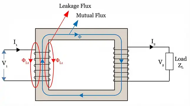
Imagine a simple single-phase transformer with two windings placed on a common iron core. If the primary winding produces 100 units of flux, perhaps 97 units will successfully link with the secondary winding through the core. The remaining 3 units will leak through the air around the primary coil. Those 3 units are the primary leakage flux.
2. What Is Leakage Reactance?
Leakage flux, although it does not contribute to energy transfer between windings, still induces an EMF in the winding that produces it. This self-induced EMF opposes the change in current according to Lenz’s Law. The opposition created by this self-induced EMF is modeled as a reactance in the equivalent circuit of the machine. This reactance is called leakage reactance.
Leakage reactance is an inductive reactance. It is denoted as \(X_1\) for the primary winding and \(X_2\) for the secondary winding in a transformer equivalent circuit. The value of leakage reactance depends on the amount of leakage flux, which in turn depends on the winding geometry, spacing between windings, number of turns, and frequency of operation.
Mathematically, leakage reactance is expressed as:
\(X_L = 2 \pi f L_L\)
Where:
- \(X_L\) = leakage reactance in ohms (Ω)
- \(f\) = frequency in hertz (Hz)
- \(L_L\) = leakage inductance in henrys (H)
Leakage reactance causes a voltage drop inside the machine. This internal voltage drop directly affects the output voltage delivered to the load.
3. Difference Between Mutual Flux and Leakage Flux
To understand leakage flux properly, you must first distinguish it from mutual flux.
Mutual flux is the flux that links both the primary and secondary windings through the magnetic core. It is responsible for transferring energy from one winding to the other. This is the useful flux.
Leakage flux links only with the winding that produces it. It does not participate in energy transfer. It simply causes an additional voltage drop in the winding.
| Parameter | Mutual Flux | Leakage Flux |
|---|---|---|
| Path | Through the iron core | Through air or non-magnetic material |
| Links with | Both windings | Only the producing winding |
| Contribution | Transfers energy | Causes voltage drop |
| Magnitude | Much larger | Relatively small |
| Depends on | Core material and geometry | Winding arrangement and spacing |
In a well-designed power transformer, the mutual flux constitutes about 95% to 99% of the total flux. The remaining 1% to 5% is leakage flux.
4. Causes of Leakage Flux in Transformers and Motors
Several factors contribute to leakage flux in electrical machines.
1. Physical Separation Between Windings: The greater the distance between primary and secondary windings, the more flux will leak through the air gap instead of coupling with the other winding.
2. Winding Geometry: Concentric windings placed close together on the same limb of the core produce less leakage flux compared to windings placed on separate limbs.
3. Core Saturation: If the iron core operates in the saturated region, it can no longer carry additional flux efficiently. The extra flux is forced into the air path, increasing leakage.
4. Air Gaps: In machines like induction motors, the air gap between the stator and rotor is unavoidable. This air gap is a primary source of leakage flux.
5. Number of Turns: More turns on a winding create a stronger magnetic field. If the core cannot accommodate all the flux, the excess leaks into the surrounding space.
6. Frequency: At higher frequencies, the inductance associated with leakage becomes more pronounced, increasing the leakage reactance even if the physical flux remains the same.
5. Leakage Flux and Leakage Reactance in Transformers
In a practical transformer, leakage flux and leakage reactance play a major role in determining performance characteristics like voltage regulation and short-circuit behavior.
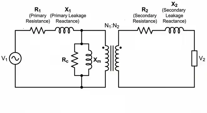
5.1 Equivalent Circuit Representation
The equivalent circuit of a real transformer includes leakage reactance for both primary and secondary windings. The primary leakage reactance \((X_1)\) is placed in series with the primary winding resistance \((R_1)\), and the secondary leakage reactance \((X_2)\) is placed in series with the secondary winding resistance \((R_2)\).
The total impedance of the primary winding is:
\(Z_1 = R_1 + jX_1\)
The total impedance of the secondary winding is:
\(Z_2 = R_2 + jX_2\)
These impedances cause a voltage drop proportional to the load current. At no load, the current is very small, so the voltage drop across the leakage reactance is negligible. At full load, this drop becomes noticeable and affects the output voltage.
5.2 Effect on Voltage Regulation
Voltage regulation is defined as the change in secondary terminal voltage from no-load to full-load, expressed as a percentage of the full-load voltage.
\(\text{% Voltage Regulation} = \dfrac{(V_{no-load} − V_{full-load})}{V_{full-load}} \times 100\)
Higher leakage reactance means a larger voltage drop at full load, which leads to poorer voltage regulation. Power transformers used in electrical power systems are designed to keep leakage reactance within acceptable limits to maintain good voltage regulation.
5.3 Example
Consider a 10 kVA, 2400/240 V single-phase transformer. If the total leakage impedance referred to the primary side is \(Z_{eq} = 3 + j5\, Ω\), then at full-load current, the voltage drop across this impedance will reduce the secondary terminal voltage. The reactive component \((j5\, Ω)\) is the leakage reactance contribution. An engineer designing this transformer would aim to minimize this value through careful winding arrangement.
5.4 Role in Short-Circuit Conditions
During a short circuit, the only thing limiting the fault current is the total impedance of the transformer, which is dominated by the leakage reactance. A transformer with very low leakage reactance will allow extremely high short-circuit currents, which can damage the windings. A transformer with higher leakage reactance will naturally limit the fault current.
This is why power system engineers specify a particular percentage impedance (often called %Z) for transformers. A typical distribution transformer may have a %Z of 4% to 6%, and most of this impedance comes from the leakage reactance. According to ANSI/IEEE C57.12.00, the impedance values for power transformers are standardized to maintain proper fault current coordination across the power grid.
6. Leakage Flux and Leakage Reactance in Induction Motors
Induction motors also experience leakage flux and leakage reactance. In fact, leakage reactance has a more complex effect in induction motors compared to transformers because of the air gap and rotating magnetic field.
6.1 Types of Leakage Flux in Induction Motors
- Slot Leakage Flux: This flux crosses from one side of a slot to the other without linking with the rotor. It is influenced by the shape and dimensions of the stator and rotor slots.
- Zigzag Leakage Flux: This type of flux zigzags across the air gap between the stator and rotor teeth. It depends on the air gap length and tooth geometry.
- End-Winding Leakage Flux: The portions of the stator and rotor windings that extend beyond the core (called end turns) produce flux that does not link with the other winding. This is end-winding leakage.
- Belt Leakage Flux: This arises from the non-sinusoidal distribution of the winding around the stator. Harmonics in the MMF distribution cause additional leakage components.
- Skew Leakage Flux: If the rotor bars are skewed (angled) relative to the stator slots, some additional leakage is introduced. Skewing is done intentionally to reduce cogging and noise, but it adds a small amount of leakage reactance.
6.2 Effect on Motor Performance
Leakage reactance in an induction motor affects several performance parameters:
- Starting Torque: Higher leakage reactance reduces the starting torque of the motor. The starting torque is inversely related to the square of the total leakage reactance.
- Maximum Torque (Breakdown Torque): The maximum torque a motor can produce is inversely proportional to the total leakage reactance. A motor with high leakage reactance will have a lower breakdown torque.
- Starting Current: Higher leakage reactance limits the inrush current at startup. This can be beneficial in reducing the stress on the power supply during motor starting.
- Power Factor: Leakage reactance contributes to a lagging power factor, especially at light loads.
The equivalent circuit of an induction motor includes stator leakage reactance \((X_1)\) and rotor leakage reactance referred to the stator side \((X_2^{‘})\). The design engineer must balance these values to achieve the desired starting and running characteristics.
6.3 NEMA Motor Design Classifications
The National Electrical Manufacturers Association (NEMA) classifies induction motors into Design A, B, C, D, and E categories based on their torque-speed characteristics, which are heavily influenced by rotor leakage reactance.
- NEMA Design A: Low rotor leakage reactance, high starting current, normal starting torque.
- NEMA Design B: Moderate rotor leakage reactance, moderate starting current, normal starting torque. This is the most common design.
- NEMA Design C: Higher rotor leakage reactance shaped for high starting torque with moderate starting current.
- NEMA Design D: High rotor leakage reactance, high slip, high starting torque.
These classifications are governed by NEMA MG 1 standards. The leakage reactance of the rotor is deliberately adjusted by changing the rotor bar shape, depth, and slot geometry.
7. Mathematical Analysis of Leakage Reactance
Let us look at a more detailed mathematical treatment of leakage reactance for a transformer.
The leakage inductance of a winding depends on the volume of the leakage flux path and the number of turns. For a cylindrical winding arrangement, the leakage inductance can be approximated as:
\(L_L = \dfrac{\mu_0 \times N^2 \times l_w \times b}{3 \times h_w}\)
Where:
- \(\mu_0\) = permeability of free space (4π × 10⁻⁷ H/m)
- \(N\) = number of turns
- \(l_w\) = mean length of the winding turn
- \(b\) = axial height of the winding
- \(h_w\) = radial depth of the winding
This is a simplified formula. In practice, finite element analysis (FEA) software is used for precise calculation of leakage inductance in transformer design.
The leakage reactance is then:
\(X_L = 2\pi f L_L\)
8. How to Reduce Leakage Flux and Leakage Reactance
Reducing leakage flux is a primary goal in the design of high-performance transformers and motors. Here are several proven methods:
8.1 Reduce the Spacing Between Windings
Placing the primary and secondary windings closer together reduces the volume of the leakage flux path. Concentric winding arrangements where one winding is wound directly over the other on the same limb are very effective.
8.2 Interleave the Windings
Instead of placing all primary turns in one section and all secondary turns in another, the windings can be divided into multiple sections and interleaved. This technique is commonly used in high-frequency transformers and audio transformers to minimize leakage inductance.
8.3 Use Sandwich Windings
In sandwich (or pancake) winding construction, alternating discs of primary and secondary windings are stacked on top of each other. This arrangement promotes better flux coupling between the two windings.
8.4 Reduce the Air Gap (in Motors)
For induction motors, minimizing the air gap between the stator and rotor reduces leakage flux. However, the air gap cannot be made too small because of mechanical constraints and the risk of rotor-stator contact.
8.5 Optimize Core Design
A well-designed core with adequate cross-sectional area prevents saturation. If the core is not saturated, almost all the flux will follow the core path instead of leaking through the air.
8.6 Use Magnetic Shielding
Copper or aluminum shields placed between windings can redirect leakage flux. This technique is used in specialty transformers where very low leakage is required.
9. Standards and Codes Related to Leakage Reactance
Several industry standards govern the measurement, specification, and testing of leakage reactance in electrical machines.
| Standard | Description |
|---|---|
| ANSI/IEEE C57.12.00 | General requirements for liquid-immersed distribution, power, and regulating transformers |
| ANSI/IEEE C57.12.90 | Test code for liquid-immersed distribution, power, and regulating transformers |
| IEC 60076 | Power transformers — General requirements and tests |
| NEMA MG 1 | Motors and generators — Includes specifications for motor reactance and design classifications |
| IEEE Std 112 | Test procedure for polyphase induction motors and generators |
These standards define how impedance and reactance tests should be performed and what acceptable ranges look like for different transformer and motor ratings. During a short-circuit test on a transformer, the measured impedance is almost entirely due to leakage reactance and winding resistance. This test is standardized in IEEE C57.12.90 and IEC 60076-1.
10. Testing and Measurement of Leakage Reactance
The most common method to determine leakage reactance is the short-circuit test (also called the impedance test).
10.1 Procedure for Short-Circuit Test on a Transformer
- Short-circuit the secondary winding terminals.
- Apply a reduced voltage to the primary winding — just enough to circulate full-load current.
- Measure the applied voltage \((V_{sc})\), short-circuit current \((I_{sc})\), and power input \((P_{sc})\).
From these measurements:
- \(Z_{eq} = \dfrac{V_{sc}}{I_{sc}}\) (equivalent impedance referred to the primary)
- \(R_{eq} = \dfrac{P_{sc}}{I_{sc}^2}\) (equivalent resistance referred to the primary)
- \(X_{eq} = \sqrt{(Z_{eq}^2 − R_{eq}^2)}\) (equivalent leakage reactance referred to the primary)
10.2 Example
A 50 kVA, 4800/240 V transformer is tested with the short-circuit test. The results are:
- \(V_{sc} = 187\,V\)
- \(I_{sc} = 10.4\,A\) (full-load current on the primary side)
- \(P_{sc} = 750 \,W\)
\(Z_{eq} = \dfrac{187}{10.4} = 17.98 \Omega\)
\(R_{eq} = \dfrac{750}{(10.4)^2} = \dfrac{750}{108.16} = 6.93 \Omega\)
\(X_{eq} = \sqrt{(17.98^2 − 6.93^2)} \)
\(X_{eq}= \sqrt{(323.28 − 48.02)} \)
\(X_{eq}= \sqrt{275.26} = 16.59 \Omega\)
The leakage reactance referred to the primary side is approximately 16.59 Ω. This value is used in the equivalent circuit for voltage regulation calculations, fault analysis, and efficiency studies.
11. Conclusion
Leakage flux and leakage reactance are fundamental concepts in electrical machine design and power system engineering. Leakage flux is the portion of magnetic flux that fails to couple both windings and instead takes a path through air or non-magnetic material. The reactance produced by this leakage flux is called leakage reactance, and it directly affects voltage regulation, fault current levels, starting torque, and overall machine performance.
Engineers can reduce leakage flux through thoughtful winding arrangements, interleaving techniques, and proper core design. However, a controlled amount of leakage reactance is actually beneficial for limiting short-circuit currents. Familiarity with standards like ANSI/IEEE C57.12.00, IEC 60076, and NEMA MG 1 helps engineers design, test, and operate electrical machines within safe and efficient operating boundaries.
12. Frequently Asked Questions (FAQs)
Leakage flux is the portion of magnetic flux produced by a winding that does not link with the other winding. It completes its path through the air or non-magnetic material instead of traveling through the iron core.
Leakage flux is caused by the physical separation between windings, air gaps in the magnetic circuit, core saturation, and the geometry of the winding arrangement.
Leakage reactance causes a voltage drop inside the transformer that increases with load current. A higher leakage reactance results in poorer voltage regulation because the output voltage drops more from no-load to full-load conditions.
No, leakage flux can never be completely eliminated in a practical machine. It can only be minimized through better winding design, closer winding spacing, and optimized core geometry.
Leakage reactance is due to the leakage flux that links with only one winding. Magnetizing reactance is due to the mutual flux that flows through the core and links both windings. Magnetizing reactance represents the current needed to establish the core flux.
Leakage reactance is measured using the short-circuit test. The secondary winding is short-circuited, a reduced voltage is applied to the primary, and the impedance is calculated. The reactive component of this impedance is the leakage reactance.
Higher leakage reactance reduces the starting torque of an induction motor. The starting torque is inversely proportional to the total leakage reactance of the motor circuit.
Yes. Leakage reactance is directly proportional to frequency (X_L = 2πfL_L). A transformer operating at 60 Hz will have a higher leakage reactance than the same transformer operating at 50 Hz, assuming the leakage inductance remains constant.