
A wave trap is an electrical device connected in series with a high-voltage transmission line. The main function of a wave trap is to block high-frequency communication signals from entering the substation equipment and allow the normal power frequency current (50 Hz or 60 Hz) to pass through it without any interruption.
In simple terms, a wave trap acts as a barrier. High-frequency signals from 30 kHz to 500 kHz are stopped from flowing into the substation busbars, transformers, or other equipment.
Another common name for this device is a line trap.
1. Why Wave Trap is Needed?
Power utilities use transmission lines not just to carry electrical power but also to send communication signals from one substation to another. This method of communication is called Power Line Carrier (PLC) communication.
PLC is used for purposes like:
- Protection signaling between substations
- Telemetry and SCADA data transmission
- Supervisory control signals
- Voice communication between substations
The communication signals are injected onto the transmission lines at high frequency. If these high frequency communication signals flow into the substation busbars, transformers, or equipment they simply get absorbed or short-circuited.
A wave trap prevents this from happening. It blocks the high-frequency signal from going into the substation and instead keeps it flowing along the transmission line toward the intended receiving end.
2. Where is the Wave Trap Installed?
A wave trap is installed at the entry point of the transmission line into a substation. It is placed in series with the line conductor just after the line enters the substation yard.
Wave trap is mounted directly on the top of a current transformer (CT) or on a separate support structure based on the substation design. This arrangement intercepts the line before the power reaches the busbar or any branching point/equipment inside the substation.
For a three phase system, each phase has its own wave trap. So for a standard three-phase transmission line, three wave traps are installed at the entry point/outgoing point of the substation.
3. Basic Working Principle
The basic working principle of a wave trap is parallel resonance. A parallel LC circuit offers very high impedance at its resonant frequency and very low impedance at other frequencies.
In a wave trap circuit, the main coil (inductor) and the tuning capacitor are connected in parallel as shown in the figure below. This parallel LC combination behaves differently at different frequencies.
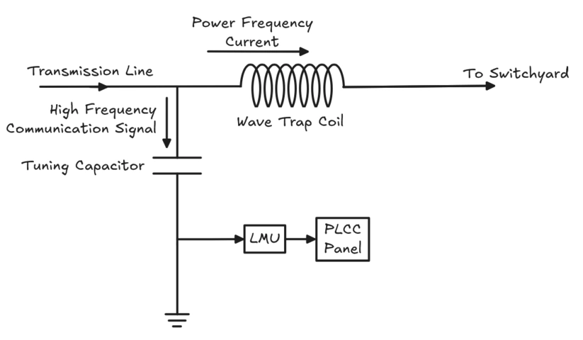
At the tuned communication frequency, the parallel LC circuit reaches resonance and offers very high impedance to the communication signal. The communication signal cannot pass through the high impedance and gets blocked.
At power frequency, the same LC circuit offers zero impedance. The power frequency current flows through the circuit without any resistance or voltage drop at the wave trap.
4. Construction of a Wave Trap
4.1 Main Coil (Inductor)
The main coil is a large inductor wound with aluminum or copper conductors. It carries the full line current at power frequency. Therefore, the coil must be designed to handle the rated current continuously without any overheating.
The inductance value of this coil should be 0.5 mH to 2 mH and depends upon the system frequency and the desired tuning range.
4.2 Tuning Device
The tuning device is a capacitor or a combination of LC components that tunes the wave trap to block the communication frequencies. It is connected in parallel with the main coil.
The tuning pack can be:
- Single frequency tuned that blocks one specific frequency
- Double frequency tuned that blocks two frequencies simultaneously
- Broadband tuned that blocks a range of frequencies
The selection of the tuning pack depends upon the number of communication channels are being used on that transmission line.
4.3 Protection Device
High-voltage surges on transmission lines can damage the tuning device. Therefore, a protection device such as a surge arrester, lightning arrester or a voltage-limiting device is connected across the tuning pack to protect it from transient overvoltages.
This protection is built into the wave trap housing.
5. Equivalent Circuit of a Wave Trap
To understand the behavior of a wave trap, consider the following equivalent circuit diagram as shown in the figure below:
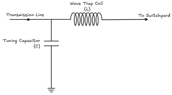
- The main coil (L) is in series with the transmission line.
- The tuning capacitor (C) is connected in parallel with L.
- Together, L and C form a parallel resonant circuit
The resonance frequency \(f_0\)) can be calculated as:
\(f_0 = \dfrac{1}{2\pi \sqrt{LC}}\)
At the resonant frequency, the parallel LC combination has maximum impedance and the communication signal is blocked from passing through.
At power frequency, the impedance is negligible, so the power frequency current flows easily.
Practical example:
If \(L = 1 mH\) and the communication frequency is \(100 kHz\), then the required capacitance \(C\) is:
\(C = \dfrac{1}{((2\pi f)^2 \times L)}\)
\(C = \dfrac{1}{((2\pi \times 100,000)^2 \times 0.001)}\)
\(C \approx 2.53 nF\)
6. Types of Wave Traps
6.1 Single Frequency Wave Trap
Single frequency wave traps are tuned to block only one frequency. These type of wave traps are used when a single communication channel is assigned to the transmission line. The tuning is easy and the device is simple in construction.
6.2 Double Frequency Wave Trap
Double frequency wave traps are designed to block two different frequencies at the same time. This type of wave trap is used when two separate communication systems such as one for protection and another one for SCADA share the same transmission line but operate at different frequencies.
6.3 Broadband Wave Trap
Broadband wave traps are designed to block a wide range of frequencies instead of one or two. This type of wave trap is used in modern PLC systems where multiple channels operate across a band of frequencies. The constructions and tuning network is complex in this type of wave traps.
7. Ratings and Specifications of a Wave Trap
| Parameter | Typical Value |
|---|---|
| System Voltage | 66 kV, 132 kV, 220 kV, 400 kV |
| Current Rating | 400 A to 4000 A |
| Communication Frequency Range | 30 kHz to 500 kHz |
| Inductance | 0.5 mH to 2 mH |
| Short Circuit Current Rating | As per system requirement |
| Minimum Blocking Impedance | 600 Ω to 1500 Ω (at tuned frequency) |
8. Coupling Capacitor and Wave Trap
A wave trap does not work alone. It works as part of a complete PLC system. The other important component is the coupling capacitor also called the line coupling capacitor. Capacitive voltage transformers are commonly used for coupling.
The coupling capacitor blocks the power frequency voltage and passes the high-frequency signals. Because of this, communication equipment can be connected to the transmission line without exposing it to high voltage.
The complete step-by-step signal flow is described below:
- The PLC transmitter generates a high-frequency signal.
- The coupling capacitor injects this signal onto the transmission line.
- The wave trap at the sending-end substation blocks the signal from going into the busbar and forces it to travel along the line.
- The signal reaches the remote substation.
- A coupling capacitor in the receiving end substation extracts the signal from the line and feeds it to the PLC receiver.
- The wave trap at that end stops the signal from spreading into the busbar.
From the above signal flow, it is clear that the coupling capacitor handles signal injection and extraction. The wave trap keeps the signal contained on the line between the two substations and does not let it to enter the substation equipment area.
9. Testing of Wave Traps
9.1 Factory Tests
- Tuning verification: The wave trap is tested to confirm whether it blocks the correct frequency.
- Current rating test: The coil is tested at rated current to verify thermal performance.
- Short circuit test: The coil is tested at short circuit level to check whether it can withstand mechanical forces during a fault.
- Power frequency voltage test: The device is tested at line voltage to check insulation.
9.2 Field Tests After Installation
- Impedance measurement at the communication frequency
- Verification of coupling and communication signal quality
- Physical inspection for damage or loose connections
10. Practical Example
Consider a 220 kV transmission line running between Substation A and Substation B. The protection engineers have set up a distance relay protection scheme that uses PLC communication at 96 kHz for tripping signals.
At Substation A:
- A coupling capacitor injects the 96 kHz signal onto the line.
- A wave trap tuned to 96 kHz is installed in series with the line at the substation exit. This blocks the signal from going into the busbar and keeps it flowing toward Substation B.
At Substation B:
- The 96 kHz signal arrives from the line.
- A coupling capacitor extracts the signal and sends it to the PLC receiver.
- Another wave trap tuned to 96 kHz is installed here to block the signal from going into Substation B’s busbars.
11. Conclusion
A wave trap is a parallel LC device connected in series with a high-voltage transmission line. It blocks high-frequency PLC communication signals (30 kHz to 500 kHz) from entering substation equipment and allows power frequency current to pass. It works on the principle of parallel resonance.
The device consists of a main coil, a tuning pack, and a surge arrester for protection. Wave traps are used in protection signaling, SCADA, and telemetry applications over power line carrier systems.
12. Frequently Asked Questions (FAQs)
A wave trap blocks high-frequency communication signals from entering the substation equipment. It allows the power frequency current to pass through without any effect.
Wave traps are installed on high-voltage and extra-high-voltage transmission lines of 66 kV and above.
Wave traps are tuned to block frequencies in the range of 30 kHz to 500 kHz. The exact frequency depends on the communication channel assigned to that particular line.
A coupling capacitor injects or extracts the high-frequency communication signal from the transmission line. A wave trap blocks that signal from entering the substation. They work together in a PLC system but serve opposite functions.
Yes. A double-frequency wave trap can block two specific frequencies simultaneously and a broadband wave trap can block a range of frequencies.
It must be in series because it needs to carry the full line current. At the same time, it needs to present high impedance to the communication signal traveling along the line.
Yes. A wave trap is a completely passive device. It has no active components, no power supply, and no electronic circuits.