Quadrilateral characteristics is one of the most sophisticated and widely-used impedance-based relay protection schemes in modern electrical power systems. These characteristics define the operating region of a distance protection relay on the R-X (Resistance-Reactance) impedance plane.
In this technical guide, we will discuss the fundamentals and core principles of quadrilateral characteristics, working principles, operating logic, advantages, limitations, practical applications, setting guidelines and commissioning procedures. We will also compare Quadrilateral Characteristics with Mho Characteristics.
What Are Quadrilateral Characteristics?
Quadrilateral characteristics are four-sided geometric shapes plotted on the R-X impedance plane that define the operating zone of a distance protection relay. Unlike circular characteristics (such as Mho or Ohm characteristics), quadrilateral characteristics are bounded by four straight lines, allowing much greater flexibility in relay protection design and setting.
The quadrilateral shape is created by independent setting parameters, each controlling one side of the polygon.
The right side is controlled by the maximum fault resistance (Rf) which determines how far to the right the protection zone extends to accommodate high-resistance arc faults.
The left side is controlled by load encroachment protection settings which ensures that the relay never trips during normal system operation when the line is carrying load current.
The top and bottom sides are controlled by reactance settings, which determine the vertical boundaries of the protection zone and define the reach of the relay along the transmission line.
In practical modern relays, the quadrilateral characteristic is actually a parallelogram that intersects the R-X axes with specific values. The polygon is defined by setting parameters including the distance angle that tilts the characteristic, and a load trapezoid that can be used to cut out the area of load impedance from the polygon.
Historical Background
Before quadrilateral characteristics became dominant, distance relays primarily used circular characteristics (Mho and Ohm characteristics). These older relay types traced circular boundaries on the impedance plane, limiting the flexibility engineers had when coordinating protection.
The transition to quadrilateral characteristics occurred in the 1980s-1990s with the advancement of microprocessor-based numerical relays. These modern relays can define complex geometric shapes easily through software-based logic, making quadrilateral characteristics the industry standard for transmission line protection today.
The development of quadrilateral characteristics represented a major breakthrough because it allowed protection engineers to independently adjust each boundary of the protection zone, rather than having all boundaries tied to a single center point as in circular relays.
Why Quadrilateral Characteristics Are Important
Quadrilateral characteristics solve several critical problems in distance relay protection from earlier relay designs.
The first major advantage is load encroachment avoidance. The left vertical boundary of the quadrilateral prevents false tripping during high load conditions by maintaining a minimum resistance margin that normal system loads cannot exceed, no matter how the system load varies.
Second, they offer excellent fault resistance tolerance through the right vertical boundary, which can be set to protect high-resistance arc faults that occur in dry weather or when insulators are contaminated with pollution.
Third, quadrilateral characteristics enable improved selectivity and discrimination between internal faults on the protected line and external faults on neighboring lines. This selectivity ensures that only the relay closest to the fault operates.
Fourth, they can be shaped to detect and handle power swing conditions (oscillations that occur when generators swing back and forth at different frequencies), which is increasingly important in modern power systems with complex generator interconnections.
Finally, their independent adjustability means protection engineers can customize the shape for different system conditions without requiring additional hardware or making complex manual adjustments.
Fundamental Terms
1. Xf (Forward Reactance)
Forward Reactance is the most important parameter for setting the reach of distance protection. It represents the maximum reactance value that the relay will allow before the protection zone boundary cuts off protection.
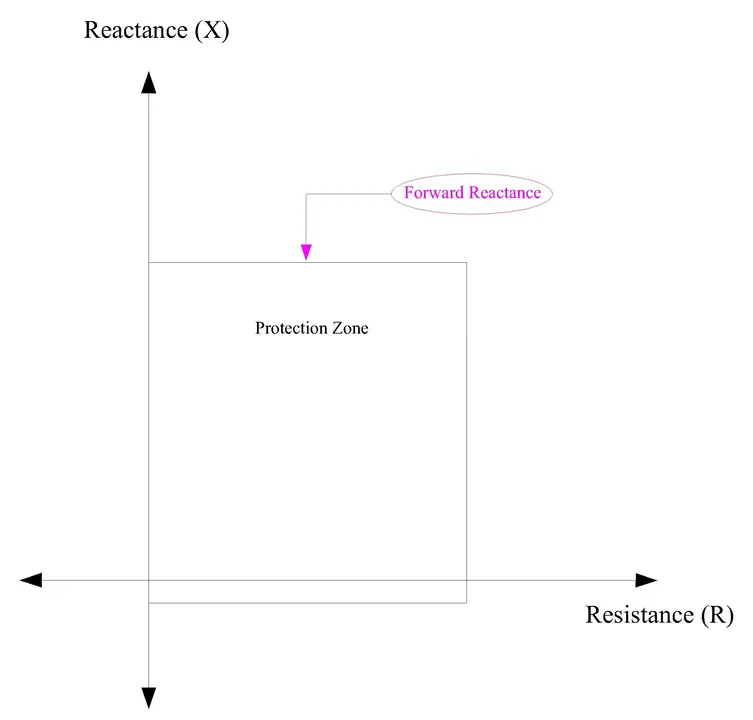
In simpler terms, Xf defines the “height” of the top boundary of the quadrilateral on the R-X plane.
For a transmission line, Xf is typically set to between 80% and 85% of the line’s total reactance for Zone 1 protection.
For example, if a 50-km transmission line has a total reactance of 2.5 Ohms, then Xf for Zone 1 might be set to 0.85 × 2.5 = 2.125 Ohms.
This setting ensures that Zone 1 protection covers approximately 85% of the line length. Beyond this reactance value, the relay moves to its second zone of protection with a longer time delay.
2. Rf (Maximum Fault Resistance)
Maximum Fault Resistance defines the right vertical boundary of the quadrilateral and represents the maximum amount of fault resistance that the relay will still detect and respond to. Resistance in faults comes from the arc that develops when electricity jumps between conductors or from a conductor to ground.
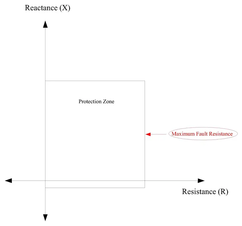
A dry fault with high arc resistance might have 20, 30, or even 40 Ohms of resistance, while a wet fault might have only a few Ohms.
The Rf parameter tells the relay, “If this fault has up to this much resistance, trip anyway.”
For most transmission line applications, Rf is set between 20 and 50 Ohms. If Rf is set too low, high-resistance faults won’t be detected and the line won’t be protected. If Rf is set too high, the relay might respond to faults on adjacent lines, causing false trips and loss of power to healthy circuits.
3. R_load (Load Resistance or Load Impedance)
Load Resistance or Load Impedance represents the resistance component of the normal power being transported through the protected line during typical system operation. This parameter defines the left vertical boundary of the quadrilateral, essentially creating a load encroachment protection margin.
During normal operation, the impedance of the power flowing through the line must always fall to the left of this boundary (meaning it must have less resistance than R_load).
If a fault occurs, the impedance point will move to the right, entering the protection zone.
For example, on a 220-kV transmission line carrying 1500 Amperes at a power factor of 0.9, the load impedance might be approximately 0.15 Ohms. R_load would then be set to about 1.3 times this value (130% margin) to ensure no false trips, so R_load ≈ 0.2 Ohms. This 30% margin provides safety against measurement errors and system variations.
4. Xr (Reverse Reactance)
Reverse Reactance sets the lower boundary of the quadrilateral protection zone and provides directional protection by limiting how far the relay will reach in the reverse direction (backward toward the source feeding the relay).
Transmission lines are typically fed from two ends, and we only want the relay to protect faults in the forward direction (downstream from the relay location). Without reverse reactance setting, a large external fault in the reverse direction might be detected.
Xr is typically set to between 20% and 40% of the line’s forward reactance.
For example, if Xf is 2.5 Ohms, then Xr might be 0.3 × 2.5 = 0.75 Ohms. The bottom boundary of the quadrilateral then becomes X = -0.75 Ohms, which means negative reactance values below -0.75 Ohms would be outside the protection zone.
5. X₀ (Reactance Offset or X-axis Offset)
Reactance Offset or X-axis Offset is an optional parameter that shifts the entire quadrilateral vertically on the R-X plane. This parameter is used to fine-tune the protection zone shape for unusual system conditions or to provide additional flexibility in protection coordination.
X₀ is particularly useful when protecting series-compensated transmission lines (lines with capacitors inserted to improve power flow) or when dealing with unusual fault characteristics.
In most standard applications, X₀ is set to zero, meaning no vertical shift is applied. However, in advanced protection schemes, particularly for high-voltage or ultra-high-voltage lines with series compensation, X₀ might be adjusted to 0.1 to 0.2 Ohms to improve performance.
How Quadrilateral Characteristics Work?
The quadrilateral distance relay operates through a continuous cycle of measurement, calculation, and decision-making that repeats many times per second. Modern numerical relays perform impedance calculations at high frequency, typically 64 times or more per cycle of the system frequency (50 Hz or 60 Hz).
Step 1:
The relay measures the voltage using voltage transformers connected to the transmission line and measures the current using current transformers.
These measurements are digitized by analog-to-digital converters in the relay. The microprocessor then calculates the impedance using the formula Z = V/I and separates this impedance into its real component (resistance R) and its imaginary component (reactance X). The result is a complex impedance value R + jX that can be plotted as a single point on the R-X plane. Modern relays perform this calculation in microseconds.
Step 2:
The second step involves comparator logic and zone decision. The relay has four independent comparators that check whether the measured impedance falls within the quadrilateral protection zone.
These comparators check:
- Is R greater than R_left (preventing load encroachment)?
- Is R less than R_right (the maximum fault resistance tolerance)?
- Is X greater than X_bottom (the reverse reactance limit)?
- Is X less than X_top (the forward reactance reach)?
The relay implements this logic as:
IF (R > R_left) AND (R < R_right) AND (X > X_bottom) AND (X < X_top)
THEN Impedance is inside Zone = TRUE.
All four conditions must be true simultaneously for the relay to consider the impedance as being inside the protection zone.
Modern relays implement this logic through simple AND/OR gates making execution extremely fast, checking four numerical comparisons requires only nanoseconds even in slower microprocessors.
Step 3:
The third step is timer initiation when the relay detects that the impedance point has entered a protection zone.
- For Zone 1, most relays operate instantaneously with no intentional time delay (or an extremely short delay of 10-30 milliseconds).
- For Zone 2, the relay starts a timer that typically counts down from 300-500 milliseconds.
- For Zone 3, the timer counts down from 1-2 seconds.
Step 4:
The fourth step is trip signal generation and circuit breaker opening when the timer expires (in the case of Zone 2 and 3) or immediately (in the case of Zone 1).
The relay sends an electrical pulse signal to the circuit breaker’s trip coil through copper wiring or fiber optic cables. The circuit breaker responds by opening its main contacts, which physically separates the transmission line from the power system at both ends.
Example Scenario: A Complete Fault Detection Sequence
To make these operating principles concrete, let’s walk through a specific example scenario where a real three-phase short circuit fault occurs on a transmission line. This scenario is based on realistic fault conditions that would occur on actual 132-kV transmission lines.
1. Line Data
Consider a 132-kV transmission line that is 34.085 kilometers long with a line reactance of 0.19305 Ω/km, giving a total line reactance of approximately 6.577 Ω.
A relay is located at Substation A at one end of the line. The line extends downstream to Substation B.
At time T = 0, a three-phase short circuit fault occurs at exactly 10 kilometers from Substation A, which is approximately 29% of the line length.
The arc resistance at the fault point is 3 Ohms.
2. Relay Calculation
The relay must first calculate the impedance to the fault location. This consists of two parts: the line impedance from the relay to the fault point, plus the fault resistance.
From relay to 10-km point, the line impedance is
\(\frac{10}{34.085} \times (0.4 + j6.577) = 0.117 + j1.931\,Ω\)
Adding the 3-Ohm fault resistance:
\(Z_{measured} = (0.117 + 3) + j1.931 = 3.117 + j1.931\, Ω\)
This impedance is plotted on the R-X plane at point (3.117, 1.931).
The relay now checks all four boundaries assuming Zone 1 settings as:
- R_left = 0
- R_right = 7.50 Ω
- X_bottom = -1.32 Ω
- X_top = 5.26 Ω.
Checking each condition:
- Is R (3.117) less than 7.50? YES.
- Is X (1.931) less than 5.26? YES.
Both conditions are true, so the impedance point (3.117, 1.931) falls inside the Zone 1 quadrilateral. The relay detects a fault.
3. Relay Operation
Since this is Zone 1, the relay operates instantaneously (or with a very short ~20 millisecond delay).
At approximately T = 0.02 seconds, the relay sends a trip signal to the circuit breaker. The circuit breaker receives the signal and opens its contacts within 40-80 milliseconds. The fault is cleared by approximately T = 0.1 seconds.
The transmission line is isolated from the power system, the fault current stops flowing, and the power system is protected from further damage.
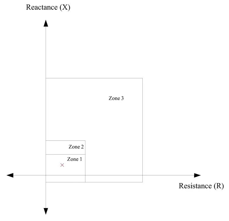
Visualization on the R-X Impedance Plane
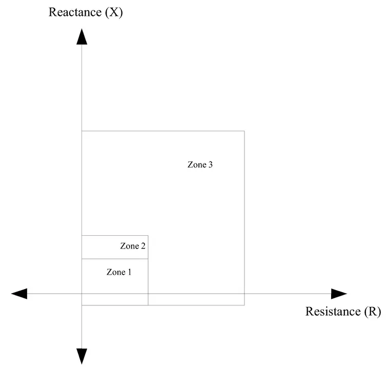
The diagram shows the impedance plane with Resistance (R) on the horizontal axis, typically ranging from 0 to 30 Ohms, and Reactance (X) on the vertical axis, typically ranging from -2 to +18 Ohms or beyond depending on the system size.
The quadrilateral itself is drawn as a closed four-sided shape, with the interior representing the protected zone (where the relay will trip) and the exterior representing the unprotected zone (where the relay will not trip).
For the above Transmission Line example, the Zone 1 quadrilateral would have corners approximately at (0, -1.32), (7.50, -1.32), (7.50, 5.26), and (0, 5.26) in Ohms on the R-X plane, representing a rectangular protection zone.
Zone 2 extends further to (7.50, 7.90) on the reactance axis, providing protection beyond the end of the line.
Zone 3 reaches even further at (18.40, 18.40) reactance.
Quadrilateral vs Mho Characteristics
| Characteristic Aspect | Quadrilateral Characteristic | Mho Characteristic |
|---|---|---|
| Shape on R-X Plane | Four-sided polygon (rectangle or trapezoid) | Circle centered on the R-X plane |
| Number of Boundaries | Four independent straight lines | One circular arc |
| Number of Independent Parameters | Five (Xf, Rf, R_load, Xr, X0) | Three (Reach, Center point, Directional angle) |
| Load Encroachment Protection | Excellent – dedicated left vertical boundary | Good but limited – must avoid circle entirely |
| Fault Resistance Tolerance | Excellent – right vertical boundary | Good but limited – depends on circle position |
| Reach Setting Flexibility | Very high – R and X set independently | Limited – reach is radial from center |
| Directional Capability | Inherent through shape – left/right boundaries | Requires separate directional unit |
| Implementation Complexity | Simple – four boundary comparators | Moderate – distance calculation needed |
| Computation Speed | Extremely fast – linear inequalities | Fast – requires radius calculation |
| Application in Modern Relays | Industry standard for new installations | Used mainly in older/backup relays |
| Flexibility for System Variations | High – adapts to series compensation, weak systems | Limited – circle shape cannot be modified |
| Communication-Aided Protection | Easy – remote signals modify boundaries | Difficult – requires complex processing |
Advantages of Quadrilateral Over Mho Characteristics
Superior Load Encroachment Protection
This stands out as the most significant advantage of quadrilateral characteristics:
- Left vertical boundary: Provides absolute impedance barrier that loads cannot exceed
- Fixed boundary advantage: Load points cannot penetrate the protection zone regardless of load variations
- Mho limitation: Curved boundary depends on circle center position; high loads might creep into protection zone
- System variations handled: Can manage unusual power factors, weak systems, series-compensated lines
- Practical benefit: Prevents false trips in systems with variable load and unusual conditions
Enhanced Fault Resistance Tolerance
The second major advantage of quadrilateral characteristics:
- Right vertical boundary: Set directly to maximum expected fault resistance (20-50+ Ω)
- Direct reach: Can extend to very high resistance values without affecting other parameters
- Mho limitation: Reach in resistance direction depends on circle radius and center position
- Trade-off issue in Mho: Increasing circle radius to improve fault resistance reach also expands reach in all directions
- Selectivity benefit: Quadrilateral improves fault resistance tolerance without losing selectivity
Improved Protection Selectivity and Coordination
Results from the independent adjustability of quadrilateral boundaries:
- Independent boundaries: Each can be set precisely without compromising others
- Optimal zone settings: Left boundary protects load without affecting fault resistance reach
- Right boundary independence: Sets fault resistance without affecting load protection
- Coordination advantage: Enables precise coordination between adjacent relays
- Mho trade-off: Interdependent parameters force engineers to make compromises
Out-of-Step and Power Swing Detection
An advanced protection function that quadrilateral characteristics handle effectively:
- Power swing locus: Traces ellipse on R-X plane during oscillations
- Quadrilateral adaptation: Shape can be modified to track elliptical locus
- Swing detection logic: Can be programmed to recognize oscillatory pattern
- Mho limitation: Fixed circular shape cannot easily follow arbitrary elliptical path
- Protection benefit: Prevents false trips during large system disturbances
Flexibility for Modern Power Systems
Increasingly important as transmission systems become more complex:
- Series-compensated lines: Quadrilateral adapts through modified settings
- FACTS devices: Can be accommodated through parameter adjustment
- Weak systems: Modified boundaries provide better performance
- Renewable energy: Converter characteristics can be addressed
- Mho limitation: Limited flexibility restricts application in new system designs
Reduced Hardware Complexity
Compared to older relay designs:
- Simple logic comparators: Only four inequality checks needed
- No transcendental functions: Avoid complex calculations like square root or trigonometric functions
- Faster operation: Microsecond-level response times
- More reliable: Fewer computational errors
- Easier troubleshooting: Simpler logic easier to diagnose
Limitations and Challenges of Quadrilateral Characteristics
Complex Setting Calculations
Protection engineers must understand multiple interdependent parameters:
- Five independent parameters: Xf, Rf, R_load, Xr, X₀
- Plus additional settings: Time delays, directional settings
- Multiple zones: Three separate zone settings required
- Interaction effects: Parameters affect each other in non-obvious ways
- Risk: Errors in any calculation can compromise protection
Load Data Uncertainty
Making it difficult to set R_load correctly:
- Varying loads: System loading changes with time, season, economic conditions
- Estimation challenge: Maximum load impedance must be accurately predicted
- Under-estimation risk: If load is underestimated, relay might trip falsely on heavy load
- Over-estimation risk: If load is overestimated, protection zone becomes larger than necessary
- Mitigation: Conduct load flow studies for summer, winter, and various scenarios
Fault Resistance Variability
Predicting maximum fault resistance is difficult:
- Variable factors:
- Fault location
- Weather conditions (wet vs dry)
- Altitude effects
- Soil conductivity
- Season
- Typical solution: Use standard value (like 25 Ω) based on regional experience
- Optimization challenge: Standard value may not be optimal for every individual line
High-Speed Numerical Processing Required
Quadrilateral characteristics cannot be implemented in older relay types:
- Requirement: Microprocessor-based numerical relays only
- Limitation: Electromechanical relays cannot use quadrilateral characteristics
- Cost implication: Modern relays required for quadrilateral protection
- Availability: Now standard in all modern relay platforms (increasingly less of a limitation)
Interaction with Unusual System Conditions
Requires ongoing attention and possible adjustment:
- High infeed situations: Multiple sources change apparent impedance
- Phase-shifting transformers: Cause apparent impedance changes
- Weak systems: System strength is low, impedance becomes unpredictable
- Frequency variations: Off-nominal frequencies affect measurements
- Solution: Modern adaptive relays automatically adjust settings
Setting Calculations and Methodology
Protection engineers follow a systematic procedure when calculating quadrilateral distance relay settings.
Step 1:
The first step is to collect system data including the line length (L = 34.085 km), line resistance (R = 0.1622 Ω/km), and line reactance per unit length (X = 0.3861 Ω/km).
This gives total line impedance of 0.4 + j6.577 Ω.
They must also collect data about the downstream system, maximum load impedance, and expected fault resistance in the region.
Step 2:
The second step is to calculate forward reactance settings for each zone.
For Zone 1, using the standard 80% setting:
\(Xf_{Z1} = 0.80 \times 6.577 = 5.26 Ω\)
For Zone 2, using 120%:
\(Xf_{Z2} = 1.20 \times 6.577 = 7.89 Ω\)
For Zone 3, using 280%:
\(Xf_{Z3} = 2.80 \times 6.577 = 18.42 Ω \)
Step 3:
The third step is to determine resistance boundaries. The maximum fault resistance for the region is estimated based on soil conditions and typical fault characteristics.
For this 132-kV line, Rf values of 7-8 Ohms for phase-to-phase faults and 10-11 Ohms for phase-to-earth faults are reasonable based on expected arc resistance and ground conditions in the region.
Step 4:
The fourth step is to verify that the load point will not cause false operation. During maximum system load, the load impedance must remain to the left of the R_load boundary.
With R_load settings of 30-45 Ohms provides substantial protection even during heavily loaded conditions.
Step 5:
The fifth step is to verify coordination with adjacent relays.
The Zone 2 reach of 120% should extend beyond the next upstream relay’s Zone 2, ensuring that if the upstream relay fails, this relay will back it up.
Zone 2 time delay of 0.35 seconds should be greater than the upstream relay’s Zone 1 delay (typically 0.00 seconds) plus a coordination margin (typically 0.2-0.4 seconds), achieving proper grading.
Testing, Commissioning, and Maintenance
Site tests verify that the relay operates correctly with the actual power system and all connected equipment. Secondary injection tests are the primary site test method. Using specialized test equipment, technicians inject known voltage and current signals into the relay’s input terminals, simulating various fault conditions. The relay’s response (whether it trips, which output relay closes, how quickly it responds) is carefully observed and recorded.
Test 1: Zone 1 Reach Verification
- Inject impedance = 0.85 × line impedance
- Relay should pick up → Verify reach ✓
- Inject impedance = 1.0 × line impedance
- Relay should not pick up (outside Zone 1) ✓
Test 2: Load Encroachment Protection
- Inject maximum load impedance
- Relay must NOT trip ✓
- Overlay fault signal on load signal
- Relay should trip → Confirms fault detection ✓
Test 3: High Fault Resistance Detection
- Inject impedance with 20 Ω resistance
- Relay should trip (within Rf = 25 Ω) ✓
- Inject impedance with 30 Ω resistance
- Relay should NOT trip (exceeds Rf) ✓
Test 4: All Fault Types
- A-B phase fault: Test and verify ✓
- B-C phase fault: Test and verify ✓
- C-A phase fault: Test and verify ✓
- A-ground fault: Test and verify ✓
- B-ground fault: Test and verify ✓
- C-ground fault: Test and verify ✓
Time delay tests:
- Zone 2 timer: Verify delay time ±20 ms
- Zone 3 timer: Verify delay time ±50 ms
- Confirm proper coordination with other relays
Communication signal tests (if applicable):
- Remote relay signals received and processed correctly
- Communication-aided functions operate as designed
- Proper signal interpretation confirmed
Circuit breaker coordination:
- Trip signal timing verified
- Circuit breaker has sufficient time to open before arc damage occurs
- Overall system response time acceptable
Conclusion
Quadrilateral characteristics represent the pinnacle of distance protection relay technology, offering unmatched flexibility, reliability, and protection performance for transmission line systems. By utilizing four independent boundaries on the R-X impedance plane—each controlled by separate setting parameters (Xf, Rf, R_load, Xr, X₀)—quadrilateral characteristics overcome the fundamental limitations of earlier circular characteristics while providing superior load encroachment protection, fault resistance tolerance, and directional discrimination.
References and Further Reading
- IEEE C37.113-2015: “IEEE Guide for Protective Relay Applications on Power Distribution Feeders”
- IEEE C37.2-2008: “IEEE Standard Electrical Power System Device Function Numbers, Acronyms, and Contact Designations”
- IEC 60255-121: “Measuring relays and protection equipment – Part 121: Functional specifications for distance protection schemes”
- J. Lewis Blackburn: “Protective Relaying: Principles and Applications” (3rd Edition)
- Modern Numerical Relay Testing and Configuration Guides from ABB, Siemens, GE