Electrical protection systems have changed a lot over the decades. In the early days of power engineering, electromechanical relays were the standard protection devices used in switchgear panels, substations, and industrial plants. These relays had coils, springs, and moving contacts that would wear out over time. As electrical systems grew more complex and demanded faster and more accurate protection, engineers needed something better. That is where static relays came in.
A static relay is a type of protective relay that uses semiconductor components such as transistors, diodes, thyristors, and operational amplifiers to perform measuring and switching functions. There are no moving parts involved. The term “static” refers to the fact that these relays have no mechanical motion during their operation. This makes them faster, more accurate, and longer-lasting compared to older electromechanical designs.
In this technical guide, we will discuss everything you need to know about static (solid-state) relays, including their working principle, types, applications, settings, testing methods, and relevant industry standards. Practical examples are included throughout to help you apply these concepts in real-world scenarios confidently.
1. What is a Static (Solid-State) Relay?
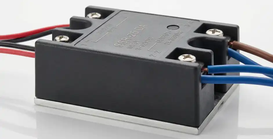
A static relay also called a solid-state relay (SSR) is a protection or switching device that performs its function using electronic components without any physical movement. The relay receives an input signal (usually current or voltage from a measuring transformer), processes that signal using internal semiconductor circuits, and generates an output signal to trip a circuit breaker or energize a contactor.
The word “static” simply means there are no moving mechanical parts. Everything happens electronically. A transistor switches on or off. A thyristor fires when a gate signal is applied. An operational amplifier compares two signal levels. All of this happens in milliseconds or even microseconds.
Static relays were first introduced in the 1960s as an alternative to electromechanical relays. They became widely adopted during the 1970s and 1980s. Today, they occupy a space between the older electromechanical relays and modern numerical (digital) relays.
2. How Does a Static Relay Work? (Working Principle)
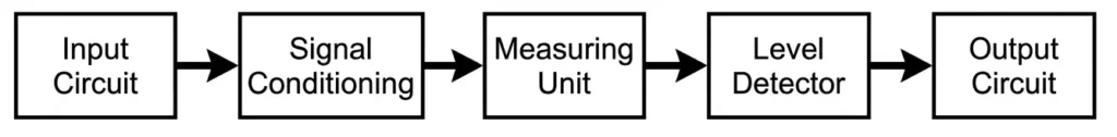
The working principle of a static relay can be understood by looking at its internal structure. A static relay has five main functional blocks that work in sequence to detect an abnormal condition and generate a trip signal.
2.1 Input Circuit
The input circuit receives signals from instrument transformers specifically current transformers (CTs) and voltage transformers (VTs or PTs). These transformers step down the high system currents and voltages to lower, manageable levels (typically 1A or 5A for CTs, and 110V or 115V for VTs). The input circuit then filters and scales these signals for the internal processing circuits.
For example, in a feeder protection application, the CT ratio might be 400/5A. The CT secondary current (5A at full load) is fed into the static relay’s input circuit.
2.2 Signal Conditioning Circuit
The signal conditioning section prepares the input signal for the measuring circuit. This block includes rectifiers (to convert AC signals to DC), filters (to remove noise and harmonics), and amplitude scaling circuits. Operational amplifiers are commonly used here.
2.3 Measuring Unit
This is the heart of the static relay. The measuring unit compares the processed input signal against a reference quantity or set point. Depending on the relay type, this measuring unit may calculate:
- The magnitude of current (for overcurrent relays)
- The ratio of voltage to current or impedance (for distance relays)
- The difference between two currents (for differential relays)
- The frequency deviation (for frequency relays)
Analog comparators or op-amp circuits perform this measurement function in static relays.
2.4 Level Detector (Threshold Circuit)
Once the measuring unit produces an output, the level detector checks if that output has exceeded a predetermined threshold. This threshold is the relay setting. If the measured quantity exceeds the set point, the level detector activates the next stage.
For instance, in an ANSI 50 instantaneous overcurrent relay, if the measured current exceeds 1000A (the set pickup value), the level detector fires immediately.
2.5 Output Circuit
The output circuit converts the electronic signal from the level detector into an action usually closing or opening a set of contacts to send a trip command to a circuit breaker. Static relays use thyristors, transistors, or optocouplers to drive output relays or directly send trip signals.
The entire sequence from sensing the fault to generating the trip signal can happen in less than one cycle (less than 20 milliseconds on a 50 Hz system).
3. Types of Static Relays
Static relays come in several types based on the protection function they perform. Each type uses a different internal circuit to measure the relevant electrical quantity.
3.1 Static Overcurrent Relay (ANSI 50/51)
A static overcurrent relay measures the magnitude of the current flowing in the protected circuit. The CT secondary current is rectified and filtered to produce a DC signal proportional to the AC current magnitude. This DC signal is compared with a reference voltage (which represents the relay pickup current setting).
There are two subtypes:
3.1.1 Instantaneous Overcurrent (ANSI 50)
The relay trips immediately (without intentional delay) when the current exceeds the pickup value. A simple comparator circuit performs this function. Response times can be as low as 8–10 milliseconds.
3.1.2 Time-Overcurrent (ANSI 51)
The relay trips with a time delay that decreases as the fault current increases. This inverse-time characteristic is achieved using an RC charging circuit or an analog integrating amplifier. The time-current characteristic curves (Standard Inverse, Very Inverse, Extremely Inverse) are programmed into the circuit using different component values.
Practical Example: A 415V distribution feeder supplies a factory load. A static ANSI 51 relay is set with a pickup of 200A and a Time Multiplier Setting (TMS) of 0.3 on a Standard Inverse curve. At a fault current of 1000A (5× pickup), the relay will operate in approximately 0.54 seconds, allowing time for a downstream fuse to clear the fault first.
3.2 Static Distance Relay (ANSI 21)
A static distance relay measures the impedance (Z = V/I) between the relay location and the fault point. If the measured impedance falls within a set zone, the relay trips.
The static distance relay uses two comparators internally:
- A phase comparator or amplitude comparator compares the input voltage and current signals in terms of their phase relationship or magnitude ratio.
- The operating characteristic (mho, reactance, or quadrilateral) is determined by how these comparators are connected and what reference signals they use.
A mho relay (the most common type) has a circular operating characteristic on the R-X (resistance-reactance) diagram. The static mho relay uses a phase comparator that checks whether the angle between two derived signals falls within 90°. If it does, the relay operates.
Zone Reach Settings:
- Zone 1: Set to 80% of the protected line impedance. Operates instantaneously.
- Zone 2: Set to 120% of the line impedance. Operates with a 300–400 ms delay.
- Zone 3: Set to cover 100% of the line plus 100% of the next line. Operates with a 600–800 ms delay.
Practical Example: A 132 kV transmission line has a positive-sequence impedance of 10 ohms. Zone 1 of the static distance relay is set to 8 ohms (80%). A three-phase fault occurs at 7 ohms from the relay location. Since 7 ohms is within the Zone 1 reach, the relay trips instantaneously.
3.3 Static Differential Relay (ANSI 87)
A static differential relay compares the current entering a protected zone (a transformer, generator, bus, or cable) with the current leaving it. Under normal conditions, these two currents are equal (after accounting for the transformation ratio). During an internal fault, there is a difference between the two currents, and the relay operates.
The static differential relay uses an op-amp summing circuit to calculate the differential current (Id = I1 – I2) and a restraint current (Ir = (I1 + I2)/2). The relay trips when the ratio Id/Ir exceeds a set slope percentage.
Percentage Differential Protection: Most static differential relays have a percentage bias characteristic. The slope (bias) setting is usually 20–40%. This prevents false trips due to CT mismatch errors or transformer tap changer operation, which create a small differential current even under normal conditions.
Practical Example: A 10 MVA, 33/11 kV power transformer is protected by a static ANSI 87T relay. The relay is set with a minimum pickup of 20% and a slope of 30%. During an inter-turn fault inside the transformer, the relay detects a differential current of 35% of the rated current. Since 35% exceeds the 20% minimum pickup and also exceeds the bias threshold, the relay trips the transformer.
3.4 Static Voltage Relay (ANSI 27/59)
Static voltage relays monitor the terminal voltage of a power system component. The VT secondary voltage is processed and compared with a reference.
An undervoltage relay (ANSI 27) operates when the voltage drops below the set threshold. This is used to protect motors from running at low voltage (which causes high currents and overheating) and to initiate load shedding schemes.
An overvoltage relay (ANSI 59) operates when the voltage rises above the set threshold. This protects equipment insulation from excessive voltage stress. Overvoltage can occur during load rejection events or Ferranti effect conditions on long transmission lines.
The static voltage relay uses a precision rectifier circuit followed by a comparator with hysteresis to prevent chattering near the threshold.
Practical Example: A 6.6 kV motor bus has a static ANSI 27 relay set to trip at 90% of nominal voltage (5.94 kV) with a 2-second time delay. This allows for short-duration voltage dips (caused by motor starting) without unnecessary trips, while protecting against sustained undervoltage conditions.
3.5 Static Frequency Relay (ANSI 81)
A static frequency relay monitors the system frequency and operates when it deviates from the nominal value. It is used in load shedding schemes and islanded power system protection.
The relay measures frequency using a zero-crossing detection circuit or a phase-locked loop (PLL) circuit. Each time the AC waveform crosses zero, the relay measures the time between crossings to calculate the instantaneous frequency.
ANSI 81O – Overfrequency relay: Trips when frequency exceeds nominal (e.g., 50.5 Hz on a 50 Hz system).
ANSI 81U – Underfrequency relay: Trips when frequency drops below nominal (e.g., 49 Hz). This is used in automatic load shedding to prevent a total system collapse.
Practical Example: In a large industrial plant connected to the grid, a static ANSI 81U relay is set to disconnect non-essential loads at 49.2 Hz. During a grid disturbance, the frequency drops to 49.0 Hz. The relay trips the feeder to non-critical loads within 100 milliseconds, reducing the burden on the grid and allowing frequency recovery.
3.6 Static Directional Overcurrent Relay (ANSI 67)
A static directional overcurrent relay adds directionality to the overcurrent function. It operates only when the overcurrent flows in a specific direction. This is important in ring-main feeders, parallel transformers, or interconnected networks where fault current can flow from multiple directions.
The directionality is achieved by comparing the phase angle between the fault current and a reference voltage (polarizing quantity). A phase comparator circuit performs this function. The relay operates only if the phase angle falls within the operating zone (typically ±90° from the maximum torque angle).
4. Input/Output Isolation in Static Relays
One of the most important design features of a static relay is electrical isolation between the input (instrument transformer) circuits and the output (trip) circuits. This isolation prevents high-voltage transients on the power system from damaging the sensitive semiconductor circuits inside the relay.
Isolation is achieved in two main ways:
4.1 Optical Isolation (Optocouplers)
An optocoupler uses an LED and a phototransistor separated by a transparent insulating barrier. The control signal drives the LED, which produces light. The phototransistor detects that light and conducts without any electrical connection to the input side. Optocouplers provide isolation voltages of 1000V–5000V.
4.2 Transformer Isolation
Small pulse transformers or signal transformers are used at the input stage to isolate the measuring circuits from the power circuits. These transformers also help reject common-mode noise.
This isolation is not just a design convenience, it is a safety and reliability requirement. Protection relay standards such as IEC 60255 specify impulse withstand voltages (typically 5 kV peak for 1.2/50 μs waveform) that static relay input and output circuits must survive.
5. Zero-Crossing Switching in Solid-State Relays
One feature that distinguishes solid-state relays from simple semiconductor switches is the zero-crossing switching capability. In standard switching, the relay can turn on at any point in the AC cycle. This creates a voltage transient because the load (especially inductive loads like motors or transformers) is suddenly connected to a non-zero voltage level. These transients cause electromagnetic interference (EMI) and can stress load insulation.
A zero-crossing SSR includes a zero-crossing detection circuit that monitors the AC supply waveform. The relay waits until the supply voltage crosses the zero-voltage point before completing the circuit. At zero volts, the inrush current (dv/dt) is at its lowest, so the switching transient is minimized.
Zero-crossing SSRs are preferred for resistive loads (heaters, incandescent lamps) because they produce minimal EMI. For phase-control applications (motor speed control, dimming), non-zero-crossing (random-fire) SSRs are used because they need to switch at a specific phase angle to control power delivery.
6. Relay Coordination with Static Relays
Relay coordination is the process of setting relays in a protection system so that the relay closest to the fault operates first (selectivity), while upstream relays serve as backup. Static relays are coordinated using the same principles as electromechanical relays, but their faster and more consistent operating times make coordination easier and more precise.
For time-overcurrent coordination (ANSI 50/51), the relay engineer uses time-current characteristic (TCC) curves to determine the operating times at various fault current levels. The goal is to maintain a coordination time interval (CTI) of 0.2–0.4 seconds between consecutive relay/fuse pairs.
6.1 Practical Coordination Example
Consider a 11 kV radial distribution feeder with three protective devices:
- F1 (Fuse at load end): 100A fuse
- R1 (Static ANSI 51 relay at midpoint): Set at 300A pickup, TMS = 0.2, Standard Inverse curve
- R2 (Static ANSI 51 relay at substation): Set at 600A pickup, TMS = 0.4, Standard Inverse curve
At a fault current of 1500A:
- F1 fuse clears in ~0.05 seconds
- R1 operates in ~0.3 seconds (backup to F1)
- R2 operates in ~0.7 seconds (backup to R1)
The 0.25-second gap between R1 and R2 at 1500A provides the selectivity needed for proper coordination. The static relays’ consistent operating characteristics make this coordination reliable throughout the feeder’s life.
For distance relay coordination (ANSI 21), zone reach settings and time delays are chosen so that Zone 1 trips instantaneously, Zone 2 covers the next line section with a short delay, and Zone 3 provides remote backup with a longer delay. Static distance relays maintain their impedance reach settings accurately over time, which makes distance protection coordination stable.
7. Relay Settings for Static Relays
Setting a static relay involves choosing the pickup value, time delay or time multiplier setting (TMS), and characteristic curve type. These settings are based on:
- Maximum load current – The pickup must be set above the maximum normal load current to avoid false trips.
- Minimum fault current – The pickup must be set below the minimum expected fault current to guarantee operation during all fault conditions.
- Coordination requirements – The operating time must be longer than the downstream device clearing time plus the CTI.
- Equipment protection requirements – Settings must not allow equipment to operate beyond its thermal or mechanical limits during a fault.
Most static relays provide setting adjustment through plug boards, rotary switches, or potentiometers located on the relay front panel or internal setting cards. Setting ranges and step sizes are listed in the relay’s technical data sheet.
7.1 Example – Setting a Static ANSI 51 Relay
A 415V distribution transformer feeds a feeder with a maximum load current of 250A and a maximum CT ratio of 400/5A.
- CT secondary current at full load: 250 × (5/400) = 3.125A
- Pickup setting (in CT secondary amps): Choose 4A (corresponds to 320A primary, above 250A load)
- TMS: Choose 0.3 on Standard Inverse curve
- At a fault current of 2000A (CT secondary = 25A, which is 25/4 = 6.25× pickup), operating time = 0.39 seconds from TCC curve
This setting protects the feeder while remaining coordinated with the upstream relay.
8. Testing and Commissioning of Static Relays
Testing static relays before energizing a new protection system is not optional, it is a standard industry practice. Testing confirms that the relay operates at the correct pickup level and within the specified operating time.
8.1 Primary Injection Testing
In primary injection testing, a high-current test set injects current directly into the primary of the current transformer in the circuit. This tests the complete protection chain including the CT, wiring, relay, and output contacts. Primary injection tests are usually performed during initial commissioning.
8.2 Secondary Injection Testing
In secondary injection testing, a relay test set injects calibrated current and voltage signals directly into the relay’s secondary terminals, bypassing the CTs and VTs. This is the most common method for testing static relays during routine maintenance and after any relay work.
Test steps for a static ANSI 51 relay:
- Set the relay test set to inject current into the relay’s current input terminals.
- Slowly increase the injected current until the relay pickup indicator activates. Record this value and compare it with the set pickup.
- Inject a current equal to twice the pickup. Start a timer. Record the operating time and compare it with the expected time from the TCC curve.
- Test the output contacts using a continuity tester or multimeter.
- Check the relay reset — reduce the current below pickup and confirm that the relay resets to its normal state.
8.3 Static Relay Functional Tests
After secondary injection, perform functional tests to confirm that the relay properly sends a trip signal to the circuit breaker trip coil. Use a breaker simulation relay (or the actual circuit breaker in a safe condition) to verify that the trip command results in breaker opening.
8.4 Standards for Testing
Static relay testing follows guidelines from:
- IEC 60255 series – International standard for measuring relays and protection equipment
- IEEE C37.90 – Standard for relays and relay systems associated with electric power apparatus
- IEEE C37.90.1 – Surge withstand capability (SWC) tests for relays
- ANSI/IEEE C37.90.2 – Withstand capability of relay systems to radiated electromagnetic interference
9. Static Relay vs Electromechanical Relay
It is worth understanding how static relays differ from electromechanical relays so you can appreciate why they were developed and where each type is still used today.
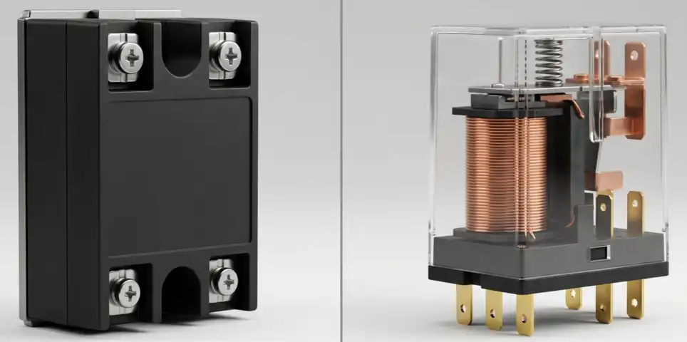
An electromechanical relay operates by electromagnetic induction. An induction disc or an attracted armature moves physically when sufficient current flows through the relay coil. This physical movement closes the trip contact. The problem is that moving parts introduce friction, wear, and inertia. Over time, contact erosion and spring fatigue affect the relay’s accuracy and operating time.
A static relay performs the same measurement and comparison functions, but entirely through semiconductor circuits. There is no disc spinning, no armature moving, and no contact bouncing. This gives static relays several advantages.
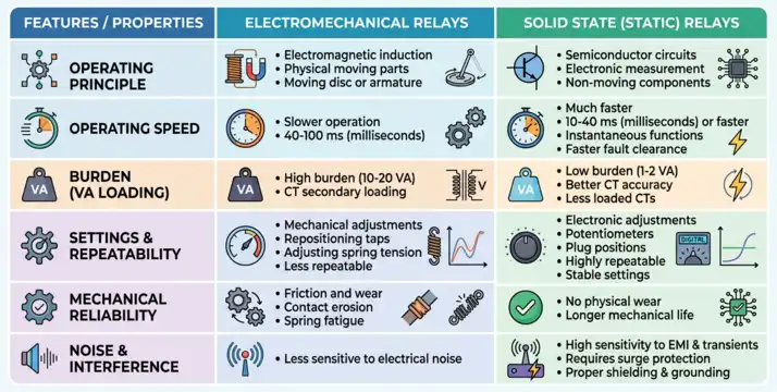
Static relays have a much faster operating speed. Electromechanical relays operate in 40–100 milliseconds for time-overcurrent functions. Static relays can operate in 10–40 milliseconds or even faster for instantaneous functions. This speed improvement leads to less equipment damage during fault conditions.
Static relays also consume less burden (VA loading) from the connected instrument transformers. An electromechanical relay might impose a burden of 10–20 VA on a CT secondary. A static relay typically imposes only 1–2 VA. This means CTs can maintain better accuracy because they are less loaded.
The settings on static relays are more repeatable and stable over time because there are no mechanical components that drift or wear out. Setting adjustments on electromechanical relays are made by repositioning taps or adjusting spring tension. Settings on static relays are made by adjusting potentiometers or selecting plug positions on a setting card.
However, static relays are more sensitive to high-voltage transients and electromagnetic interference (EMI) compared to electromechanical relays. Proper shielding, grounding, and surge suppression are needed in the installation to protect static relay circuits from electrical noise.
10. Static Relays vs Digital (Numerical) Relays
It is worth placing static relays in the broader context of relay technology generations:
Generation 1 – Electromechanical Relays: Moving parts, electromagnetic induction, slow speed, high burden. Still in service in older installations.
Generation 2 – Static (Solid-State) Relays: Semiconductor circuits, no moving parts, faster and more accurate than electromechanical, but analog in nature. No data logging or communication capability.
Generation 3 – Digital (Numerical) Relays: Microprocessor-based, use analog-to-digital converters (ADCs) and digital signal processing (DSP). Can perform multiple protection functions in one unit. Provide event logging, waveform recording, self-diagnostics, and communication via protocols like IEC 61850 or MODBUS.
Static relays still remain in use because:
- Many older substations and industrial facilities have static relay-based protection schemes that are functioning well and do not require immediate replacement.
- Static relays are simpler and more transparent to operate and maintain compared to numerical relays.
- In some developing applications or cost-sensitive projects, static relays provide adequate protection at a lower cost than full numerical relay systems.
11. Static Relay Applications
Static relays are used across a wide range of electrical engineering applications. Here are the main areas where they have proven their value:
11.1 Power System Protection
Static relays are installed in substations to protect transmission lines, distribution feeders, power transformers, generators, and busbars. They provide fast fault clearance to minimize damage and improve power system stability. A static ANSI 87T relay protecting a 132/33 kV power transformer, for instance, can clear an internal fault in under 20 milliseconds which is fast enough to prevent core damage in many fault scenarios.
11.2 Industrial Motor Control
Solid-state relays are used extensively in motor control panels and automation systems. Instead of using electromechanical contactors (which have limited contact life), SSRs switch motor loads using thyristors or TRIACs. This is especially useful in applications that require frequent switching — such as conveyors, packaging machines, and cooling fans as SSRs can handle millions of switching cycles without contact wear.
11.3 HVAC Systems
In heating, ventilation, and air conditioning (HVAC) systems, solid-state relays control resistive heating elements, compressor motors, and fan motors. The zero-crossing switching feature of SSRs (explained in the next section) reduces electrical noise and transient voltage spikes in these systems.
11.4 Process Control and Industrial Automation
PLCs (Programmable Logic Controllers) use solid-state relay output modules to control heaters, solenoid valves, small motors, and lighting circuits. The PLC output card generates a small DC control signal (typically 5V–24V DC), and the SSR uses that signal to switch a high-voltage AC or DC load.
11.5 Generator Protection
Static relays protect generators from internal faults, loss of excitation, overloading, and system disturbances. An ANSI 87G (generator differential relay) in its static form uses balanced current comparator circuits to detect inter-turn or phase-to-ground faults within the generator stator winding.
11.6 Transformer Protection
As mentioned earlier, static ANSI 87T relays protect power transformers from internal faults. In addition, static ANSI 26 (Thermal Relay) functions monitor transformer thermal conditions based on measured current loading.
11.7 Bus Protection (ANSI 87B)
Static busbar differential relays compare the sum of all currents flowing into the bus with the sum of all currents flowing out. Under normal conditions, these sums are equal. During a bus fault, the difference (differential current) activates the relay. Static bus differential relays are configured with high-impedance or low-impedance operating principles.
12. Advantages and Limitations of Static Relays
12.1 Advantages
Static relays offer a number of practical advantages that explain their widespread adoption in the electrical engineering industry.
Speed: Static relays operate much faster than electromechanical relays. This speed is important in high-fault-current systems where even a few milliseconds of extra fault duration can cause significant equipment damage.
Accuracy: Semiconductor components maintain consistent characteristics over their operating life. There is no hysteresis, no friction, and no spring fatigue all of which affect electromechanical relay accuracy over time.
Low Burden: The VA burden imposed on CTs and VTs is very small, which means the instrument transformers operate closer to their accuracy class limits more reliably.
Long Operational Life: With no moving parts to wear out, the operational life of static relay circuits is much longer. Semiconductor components can last decades in controlled environments.
Compact Size: Static relay circuits can be packaged into compact modules. Multiple protection functions can be combined into a single static relay case.
Sensitivity: Static relays can detect very small levels of abnormal quantities (small differential currents, low power factors, small frequency deviations) that electromechanical relays might miss.
Easy Setting Adjustment: Settings can be changed by adjusting a potentiometer or switching a plug — no physical reshaping or spring adjustment is needed.
12.2 Limitations of Static Relays
No technology is without limitations. Static relays have some characteristics that engineers must account for.
Susceptibility to EMI and Transients: Semiconductor circuits can be damaged by electromagnetic interference, switching transients, and lightning surges. Careful shielding, grounding, and surge protection are needed. IEC 60255 and IEEE C37.90.1 specify the transient withstand levels that relays must meet.
Temperature Sensitivity: Semiconductor components change their characteristics with temperature. Although manufacturers design relays to operate within specified temperature ranges (typically –20°C to +60°C), operation outside these ranges can affect accuracy.
Power Supply Requirement: Static relays require a stable auxiliary DC power supply (24V, 48V, or 110V DC). Loss of auxiliary power means loss of protection. Battery-backed DC systems are needed in substations.
Complexity of Fault Diagnosis: Diagnosing a faulty static relay requires test equipment and component-level troubleshooting skills. An electromechanical relay with a burned contact or bent spring is often easier to diagnose visually.
Aging of Electrolytic Capacitors: Some static relay circuits use electrolytic capacitors in timing and filtering circuits. These capacitors can dry out and lose capacitance over 10–20 years, affecting operating times. Periodic testing and maintenance are needed.
13. Industry Standards for Static Relays
Static relays must comply with international and national standards to be used in power system protection and industrial applications. The following standards are most relevant:
- IEC 60255-1: General requirements for measuring relays and protection equipment. Covers rated values, accuracy classes, burden, and environmental conditions.
- IEC 60255-151: Functional requirements for overcurrent protection relays. Defines IDMT curves, pickup accuracy, and operating time accuracy.
- IEC 60255-21: Vibration, shock, and seismic tests for relays.
- IEC 60255-22: Electrical disturbance tests including high-frequency interference, electrostatic discharge, and radiated EMI.
- IEEE C37.90: Standard relays and relay systems associated with electric power apparatus.
- IEEE C37.90.1: Surge withstand capability (SWC) tests.
- IEEE C37.113: Guide for protective relay applications to transmission lines (applicable to distance relays including static types).
- ANSI/NEMA ICS 2: Industrial control and systems — controllers, contactors, and overload relays (applicable to solid-state relay applications in motor control).
14. Conclusion
Static (solid-state) relays are an important step in the evolution of electrical protection technology. They brought the benefits of semiconductor electronics into the field of power system protection and industrial control. For electrical engineers, having a solid understanding of how these relays work, how to set them, and how to test them is a practical and valuable skill.
From protecting 132 kV transmission lines using static distance relays to switching industrial heaters with solid-state relay modules, the applications are wide and varied.
15. Frequently Asked Questions (FAQs)
These two terms are often used interchangeably, and in most engineering contexts, they mean the same thing. A relay that uses semiconductor components with no moving parts.
Static relays use a variety of semiconductor components depending on the circuit function. Diodes are used in rectifier circuits to convert AC to DC. Transistors (BJT or MOSFET) are used in amplifier and switching circuits. Operational amplifiers (op-amps) are used in comparator, integrator, and summing circuits. Thyristors (SCR) and TRIACs are used in the output switching circuit to control AC loads. Zener diodes are used in voltage reference circuits.
In most cases, yes. Static relays are available with the same CT/VT input ratings, the same ANSI protection functions, and equivalent output contact ratings as electromechanical relays. However, the engineer must verify that the static relay’s auxiliary power supply requirements, burden, and environmental ratings are compatible with the existing installation.
For instantaneous overcurrent functions (ANSI 50), static relays typically operate in 8–20 milliseconds. For time-overcurrent functions (ANSI 51), the operating time depends on the fault current magnitude and the TMS setting, and can range from 0.1 seconds to several seconds based on the characteristic curve. For distance relays (ANSI 21) in Zone 1, operating time is typically 15–25 milliseconds.
Yes. Static relays should be tested every 1–3 years depending on the application and the relay manufacturer’s recommendations. Secondary injection tests are performed to verify pickup and operating times. Output contacts are cleaned or verified for continuity.
Zero-crossing switching is a feature in solid-state relays where the relay waits for the AC supply voltage to cross zero volts before completing the circuit. This minimizes switching transients and EMI. Zero-crossing SSRs are used in resistive heating element control, incandescent lamp dimming, and HVAC control applications.
Settings on a static relay are typically adjusted using potentiometers (dial-type rotary controls), plug bridges (where a plug connector is moved to different position holes on a setting card), or rotary switches with detented positions.
IEC 60255-151 defines the accuracy classes for overcurrent protection relays, including static types.