When a power transformer arrives at a substation or project site, it often comes in an unassembled condition. Various components like the main tank, conservator tank, radiator, bushings, and Buchholz relay need to be carefully assembled at the location. This assembly process creates opportunities for leakage through loose nuts and bolts, damaged gaskets, or improper O-ring placement.
Before any oil is introduced or vacuum is applied, engineers must perform a transformer tightness test to ensure all joints are properly sealed. This step prevents catastrophic failures during commissioning and determines the transformer’s reliability during operation. Without this test, you risk moisture intrusion, insulation breakdown, oil degradation, and eventual transformer failure.
Let’s explore what makes this test essential and how to perform it correctly.
Why is Transformer Tightness Test Necessary?
When a transformer undergoes vacuuming, the process creates negative pressure inside the main tank to remove moisture from the core and windings. However, if leaks exist, this negative pressure acts like a suction pump, pulling moisture and foreign materials from the surrounding air directly into the core and windings through the leakage paths.
This can result in:
- Insulation puncture due to moisture saturation
- Sparking in the windings from moisture-contaminated insulation
- Short circuits between phases or to ground
- Reduced dielectric strength of the insulating materials
The Consequences of Leakage After Oil Filling
If you proceed with oil filling without addressing leakage, the problems multiply:
- Continuous oil loss during operation and maintenance, requiring frequent top-ups
- Oil contamination from moisture absorption through leakage paths, especially during rainy seasons
- Deteriorated insulating properties of the oil, reducing its ability to withstand electrical stress
- Increased fault risk including unnecessary sparking, short circuits, and potential explosions
How the Tightness Test Works?
The tightness test operates on a simple principle: pressurize the transformer with dry air or nitrogen and monitor for pressure loss over time.
Unlike vacuuming, which pulls moisture inward, this test creates positive pressure (higher than atmospheric) inside the transformer tank. If the tank is truly tight, the pressure will remain stable over 24 hours. Any significant pressure drop indicates leakage that must be found and fixed before proceeding.
The test uses either dry air (from a dry air generator) or nitrogen gas (from a pressurized cylinder) because these inert gases won’t react with transformer insulation and can be easily measured for moisture content (dew point).
Equipment and Materials Required
Before starting the tightness test, ensure you have the following equipment:
| Equipment | Purpose | Specifications |
|---|---|---|
| Dry Air Generator or Nitrogen Cylinder | Supply of inert gas | Dew point < -50°C |
| Pressure Gauge | Monitor gas pressure inside tank | Calibrated and accurate |
| Dew Point Meter | Measure moisture content of gas | Digital preferred for accuracy |
| Connection Hoses | Link gas source to transformer | Flexible, rated for pressure |
| Valve Tools | Operate transformer filtration valves | Standard wrench set |
| Soap Water Solution | Detect leakage location (if needed) | Liquid dish soap + water |
Step-by-Step Procedure for Transformer Tightness Test
Step 1: Prepare the Transformer
Begin by ensuring the transformer is ready for testing:
- Verify that all components are properly assembled and all bolts are hand-tight
- Shut all valves of the transformer to isolate the tank
- Seal any other openings (drain plugs, sample points, etc.)
- Inspect for any obvious damage, gaps, or disconnected components
Step 2: Set Up the Dry Air or Nitrogen Supply
Connect your gas supply equipment to the transformer:
- Attach the dry air generator hose or nitrogen cylinder to any filtration valve of the transformer
- Connect your pressure gauge to a different valve to monitor pressure inside the tank
- Ensure all connections are secure and won’t leak during testing
Step 3: Test the Dew Point of Your Gas Supply
This critical step ensures your gas is dry enough to be reliable:
- Use the dew point meter to measure the moisture content of the dry air or nitrogen at the source
- The dew point must be less than -50°C to proceed
- If the dew point is higher, adjust the dry air generator or replace the nitrogen cylinder
- Record this baseline dew point measurement
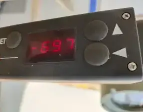
Example: In one commissioning case, the dry air measured at the generator outlet showed a dew point of -69.7°C, well within the acceptable range.
Step 4: Fill the Transformer Tank with Gas
Now pressurize the transformer:
- Open the valve connecting the gas supply to the transformer
- Allow dry air or nitrogen to flow into the tank until the pressure reaches 4-5 PSI (0.3 kg/cm²)
- Monitor the pressure gauge continuously to avoid over-pressurization
- Close the supply valve once the target pressure is reached
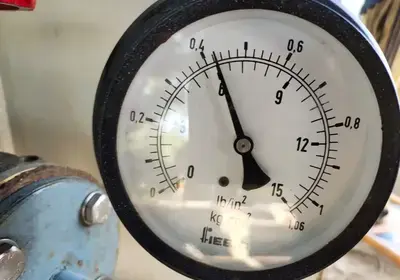
Example: In the Jiribam transformer case, after filling with dry air, the pressure gauge inside the transformer showed approximately 6 PSI, slightly above the 4-5 PSI target.
Pressure Inside Transformer Before Filling Dry Air
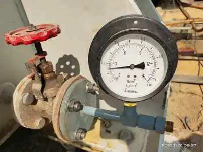
Pressure Inside Transformer After Filling Dry Air: Approx. 6 PSI.
Step 5: Seal the System and Wait 24 Hours
- Ensure the valve through which gas was filled is now closed and sealed
- Leave the transformer undisturbed for exactly 24 hours
Step 6: Check Pressure After 24 Hours
- Read the pressure gauge again without opening any valves
- Compare the current pressure to your initial pressure reading
- If pressure remains the same: The transformer is tight—proceed to the next step
- If pressure has dropped: Investigate leakage (see troubleshooting section below)
Step 7: Verify the Dew Point Inside the Tank
Now measure the moisture content of the gas inside the transformer:
- Open the valve connected to your dew point meter
- Carefully sample the gas from inside the transformer
- Record the dew point reading
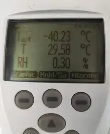
Acceptable dew point limits:
- At ambient temperature of 20-30°C, the dew point should be less than -25°C
Example: After 24 hours of pressurization, the dew point of dry air inside the Jiribam transformer measured -40°C, which is well within the acceptable range.
Step 8: Proceed to Vacuum Drop Test (If Tests Pass)
If both the pressure and dew point meet requirements, you can proceed to the final tightness test:
- The transformer is now ready for the vacuum drop test, which involves creating negative pressure and monitoring for leakage
- Only after passing both the positive pressure test and vacuum drop test should you proceed with vacuuming and oil filling
What If Pressure Drops After 24 Hours?
Temperature-Related Pressure Drop (Minor Changes)
If the pressure drop is minor and corresponds to weather changes, it can often be neglected:
Dry air is pressurized on a sunny day with an ambient temperature of approximately 30°C. The next day is rainy with a temperature of 20°C. A small pressure drop may occur due to this 10°C temperature difference.
Why? According to Gay-Lussac’s Law, gas pressure decreases when temperature decreases. A 10°C drop could result in a measurable but acceptable pressure reduction.
If the pressure drop correlates with known temperature changes and is minor (typically less than 5-10% of initial pressure), you may proceed with the vacuum drop test.
Significant Pressure Drop
If the pressure dropped significantly and doesn’t correlate with weather changes, leakage exists:
Common leakage sources:
- Joint leaks from improper tightness of nuts and bolts
- Gasket problems including improper placement or wrong gasket sizes
- O-ring damage or degradation
- Bushing leaks, particularly from oil-filled bushings (as in the Jiribam example)
- Valve stem leaks if valves were recently opened or serviced
Action steps:
- Do not proceed with vacuuming or oil filling
- Inspect all visible joints systematically
- Use soap water solution to detect leaks:
- Apply soapy water around suspected joints
- Look for bubbles forming, indicating gas escaping
- Mark all leakage points for repair
- Tighten nuts and bolts at leakage points, then repeat the test
- If leakage persists, replace damaged gaskets or O-rings
- For bushing leaks, consult the manufacturer or specialist
- After repairs, repeat the entire tightness test procedure
During the commissioning of a 20 MVA, 132/33 kV transformer in Jiribam, Manipur, persistent pressure drops indicated leakage. After 10 days of investigation—checking and rechecking nuts, bolts, gaskets, O-rings, and all valves—the leakage was finally traced to an oil-filled LV bushing. The top of the bushing had a small air release opening that was leaking. Such hidden leaks can waste tremendous time and resources if not detected early.
Dew Point and Permissible Limits
What is Dew Point?
The dew point is the temperature at which water vapor in air condenses into liquid water. A lower dew point means drier gas—exactly what transformers need.
For example:
- At a dew point of -10°C, air becomes saturated and releases moisture at this temperature
- At a dew point of -50°C, air is extremely dry and won’t release moisture even at much higher temperatures
Why Dew Point Matters
If dry air or nitrogen with high moisture content (high dew point) is introduced into a transformer:
- The moisture might condense inside the tank as temperature fluctuates
- The moisture would be absorbed by the transformer insulation
- Insulation breakdown and reduced dielectric strength would result
Permissible Dew Point During Tightness Test
The standard requirement is:
- Initial dew point of gas supply: Less than -50°C
- Dew point after 24 hours inside tank: Less than -25°C (at ambient temperature of 20-30°C)
The slight increase from -50°C to -25°C is acceptable because:
- Some moisture may be picked up from the transformer’s internal surfaces during gas pressurization
- Temperature variations during the 24-hour period can affect readings
- The -25°C threshold still ensures the gas is dry enough to prevent insulation problems
What If Dew Point Exceeds Permissible Limits?
If the dew point inside the transformer after 24 hours is more than -25°C and there is no pressure drop, moisture has been absorbed by the transformer insulation:
Implications:
- The core and windings contain absorbed moisture
- Simply vacuuming won’t remove all this moisture
- Removing moisture from insulation at the site is extremely difficult and often impossible
Action required:
- Generally, vacuuming is performed for 12 to 48 hours depending on the transformer’s voltage rating and capacity
- For large, high-voltage transformers (above 150 MVA), extended vacuum drying procedures are required
- In severe cases, the transformer may need to be returned to the factory for specialized drying treatment
- Continue monitoring dew point during the extended vacuum cycle
Dew Point vs. Temperature
Dew Point Variation for N₂ Gas-Filled Transformer Tank
| Temperature of Insulation (°F) | Permissible Dew Point (°F) | Temperature of Insulation (°C) | Permissible Dew Point (°C) |
|---|---|---|---|
| 80 | -10 | 26.66 | -23.33 |
| 85 | -6 | 29.44 | -21.11 |
| 90 | -1 | 32.22 | -18.33 |
| 95 | +3 | 34.99 | -16.11 |
| 100 | +7 | 37.75 | -13.88 |
| 110 | +16 | 43.33 | -8.88 |
| 120 | +25 | 48.88 | -3.88 |
| 130 | +33 | 54.44 | +0.55 |
| 140 | +44 | 59.99 | +5.55 |
Table 2: Permissible Dew Point for Dry Air Purging
| Temperature of Insulation (°F) | Permissible Dew Point (°F) | Temperature of Insulation (°C) | Permissible Dew Point (°C) |
|---|---|---|---|
| 0 | -78 | -17.77 | -61.11 |
| 5 | -74 | -15.0 | -58.88 |
| 10 | -70 | -12.22 | -56.66 |
| 15 | -66 | -9.44 | -54.44 |
| 20 | -62 | -6.66 | -52.22 |
| 25 | -58 | -3.33 | -49.99 |
| 30 | -53 | -1.11 | -47.22 |
| 35 | -48 | +1.66 | -44.44 |
| 40 | -44 | +4.44 | -42.22 |
| 45 | -40 | +7.44 | -39.39 |
| 50 | -35 | +9.99 | -37.22 |
| 55 | -31 | +12.77 | -34.99 |
| 60 | -27 | +15.55 | -32.77 |
| 65 | -22 | +18.33 | -29.99 |
| 70 | -18 | +23.11 | -27.77 |
| 75 | -14 | +23.88 | -25.55 |
Finding and Fixing Leaks
Using Soap Water to Locate Leaks
The soap water method is simple and effective:
- Prepare the solution: Mix liquid dish soap with water in a spray bottle
- Systematically check all joints: Starting from the top of the tank, spray suspect areas with soapy water
- Look for bubbles: Escaping gas will form bubbles in the soap film
- Mark leakage points: Use a marker or tape to flag all leak locations
- Document findings: Record which components or joints are leaking
Common areas to check:
- All bolted connections on the main tank
- Radiator connections and mounting points
- Bushing connection points
- Valve stem packing
- Oil drain and sample valve connections
- Any previously repaired or modified areas
Typical Leakage Issues and Fixes
| Leakage Source | Cause | Solution |
|---|---|---|
| Bolted joints | Improper tightness, corrosion | Retighten bolts in sequence; replace if damaged |
| Gaskets | Improper placement, damage, aging | Remove, clean, and reinstall correctly; replace if damaged |
| O-rings | Degradation, incorrect size, improper seating | Replace with correct size and material specification |
| Oil-filled bushings | Manufacturing defect or damage to bushing top | Consult manufacturer; may require bushing replacement |
| Valve stems | Packing nut loose or seal deteriorated | Tighten packing nut; replace packing or valve if needed |
| Welds | Micro-cracks or corrosion | Mark for professional repair; don’t attempt site repairs |
Conclusion
The transformer tightness test with dry air or nitrogen purging is a fundamental first step in transformer commissioning that cannot be overlooked. This test takes only 24 hours but saves weeks of troubleshooting and prevents catastrophic failures during operation.
Frequently Asked Questions
A: The tightness test ensures all joints and seals are properly sealed before introducing oil or applying vacuum. If leaks exist and you apply vacuum, the negative pressure acts like a suction pump, pulling moisture directly into the core and windings. This causes insulation breakdown and transformer failure.
A: The tightness test uses positive pressure (4-5 PSI) to verify the tank is sealed. The vacuum drop test uses negative pressure to simulate actual operating conditions. Both must be passed before oil filling.
A: No. Even brand-new transformers require tightness testing because components are assembled at the site after transport. Assembly can introduce loose bolts, misaligned gaskets, or damaged O-rings that must be detected and fixed.
A: Approximately 24-26 hours total: setup and pressurization (1-2 hours) + waiting period (24 hours) + pressure and dew point verification (30 minutes).
A: Standard pressure is 4-5 PSI (0.3 kg/cm²). This is high enough to detect leaks but low enough to safely pressurize the tank without risk of rupture.
A: It means the gas is extremely dry. If this gas is cooled to -50°C, it will just barely start to release moisture. Above -50°C, the gas remains bone dry with no moisture release.
A: Yes. After locating and repairing leaks (tightening bolts, replacing gaskets/O-rings), you must repeat the entire tightness test procedure from the beginning—another full 24-hour cycle.
A: IEC 60076-3, IEEE C57.12.00, and various national standards (like IS:1180 in India, BS:171 in UK) specify tightness test requirements. Always consult your transformer manufacturer’s documentation and local electrical codes.