
A busbar is a low-impedance metallic conductor made of copper or aluminum. Busbar collects electrical power from one or more sources and distributes the power to multiple circuits or loads connected to that busbar. Hence, the busbar acts as a common junction point and makes power distribution simple, compact, and organized.
To understand this, let us suppose, you have a 1000A incoming supply from a transformer and you need to feed that power to ten different outgoing feeders going to different parts of a factory. Instead of running ten separate cables directly from the transformer terminals, connect the transformer output to a single busbar and the connect each outgoing feeder to that busbar.
1. Why Use a Busbar Instead of Cables?
The main reason behind using busbar instead of cable is the current carrying capacity. In a very compact cross-section, a busbar can carry very high currents from a few hundred amperes to tens of thousands of amperes.
A cable carrying the same current would need to be very thick, heavily insulated, and also it will be difficult to manage such thick cable inside a panel enclosure.
In large distribution boards and switchgear, it easy to add and remove circuits in a busbar configuration. Simply connect or disconnect from the busbar. However, if cables are used instead of busbars this becomes messy and complicated.
Busbars also allow easy fault current management. In short circuit conditions, the rigid structure of a busbar can handle mechanical stress better than a cable.
2. Material Used for Busbars
The two most common materials used for construction of busbar are copper and aluminum.
Copper busbars are the most widely used busbars in industry as copper has high electrical conductivity. It also has good mechanical strength and is resistant to corrosion. However, the copper busbars are expensive.
Aluminum busbars have lower conductivity than copper. For the same current rating, an aluminum busbar needs a larger cross-section than copper. As aluminum is lighter and cheaper than copper aluminum busbars are preferred in large installations.
Some busbars are tin-plated or silver-plated on the surface to reduce contact resistance at connection joints and to prevent oxidation. Oxidation can increase resistance and generate heat at connection points.
3. Physical Form of a Busbar
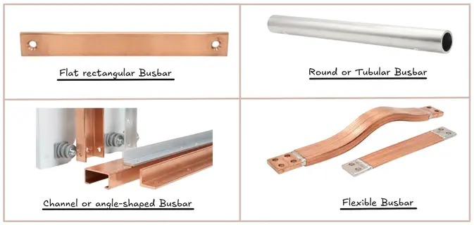
Flat or rectangular bars are the most commonly used busbars in switchgear panels and distribution boards from 400V to 11000V.
Round or tubular busbars are used in high voltage switchyards and outdoor substations. The tubular shape provides good current-carrying capacity with lower material weight.
Channel or angle-shaped busbars are used in certain busduct systems.
Flexible busbars are used in places where slight movement or vibration is present like connections to transformer terminals.
A busbar can be either bare or covered with PVC sleeving or heat-shrink insulation to prevent accidental contact.
4. Current Carrying Capacity of a Busbar
The current-carrying capacity of a busbar depends on several factors:
- Material: Copper carries more current per unit area than aluminum
- Cross-sectional area: A larger cross-section has higher current carrying capacity
- Ambient temperature: Higher ambient temperature reduces current carrying capacity
- Ventilation: A busbar in an enclosed panel runs hotter than one in open air
- Surface area: Heat dissipation depends on the surface area exposed to air
A thumb rule used by engineers is that a copper busbar can carry approximately 1 to 1.5 amperes per mm² of cross-section and an aluminum busbar can carry 0.7 to 1 ampere per mm² of cross-section in a indoor panel arrangement.
For example, a 50mm × 10mm copper busbar has a cross-section of 500mm². At 1A/mm², it can carry around 500A continuously.
5. Types of Busbars
5.1 Single Busbar System
Single busbar system is the simplest arrangement among all the types of busbars. There is one common busbar, and all feeders are connect to it. It is used in small distribution boards and simple LV panels.
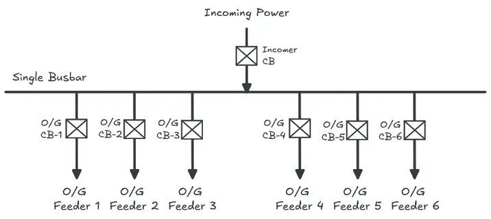
The drawback of single busbar system is that if the busbar develops a fault, the entire system loses power. There is no redundancy in this type of busbar system.
5.2 Sectionalized Busbar System
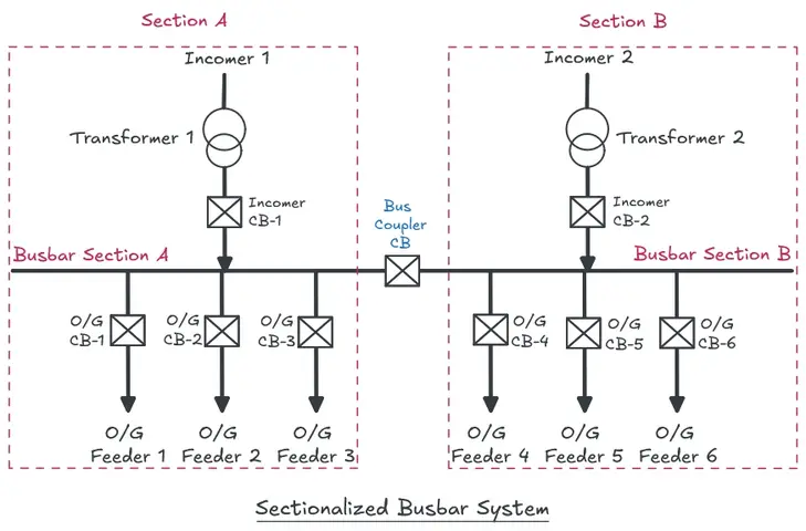
In sectionalized busbar system, the busbar is divided into two or more sections using bus coupler or bus section circuit breaker. Each section can be energized or de-energized independently.
For example, a main distribution board uses sectionalized busbar system and has two sections called Section A and Sector B. Section A is fed from Transformer 1 and Section B is fed from Transformer 2. If one transformer trips, the bus coupler circuit breaker can be closed to restore supply from the other transformer as shown in the figure below.
5.3 Double Busbar System
Double busbar system has two complete busbars running in parallel called Main Bus 1 and Main Bus 2. Each feeder can be connected to either busbar through a bus selector switch or circuit breaker.
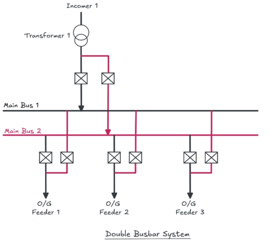
Double busbar systems are used in high voltage substations where continuity of supply is important. Maintenance can be done on one busbar while the other remains live.
5.4 Ring Busbar System
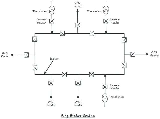
In ring busbar system, the busbar forms a closed ring as shown in the figure below. Power can flow from either direction to any point on the ring. This type of busbar system is used in large industrial power systems and grid substations.
5.5 Mesh Busbar System
Mesh busbar system is a complex arrangement used in large transmission substations. Multiple circuit breakers are arranged in a mesh pattern. This type of busbar system offers high reliability but requires a complex protection scheme.
6. Busbars in High Voltage Substations
In HV and EHV substations, busbars are installed outdoor with rigid tubular conductors supported on insulators. They are made of ACSR (Aluminum Conductor Steel Reinforced) conductor or hollow aluminum tubes.
The insulators are of post-type or disc-type and are mounted on steel structures. The clearance between busbars (phase-to-phase and phase-to-ground) is determined by the system voltage level.
For a 132kV substation, the minimum phase-to-phase clearance is 1200mm. For a 400kV substation, the minimum phase-to-phase clearance is about 3200mm.
In Gas Insulated Switchgear (GIS), the busbars are enclosed in metal cylinders filled with SF6 gas. This allows a very compact design even at 400kV or 765kV.
7. Busbar Protection
Busbars carry power to multiple feeders. A fault on the busbar like a phase-to-phase short circuit or a phase-to-earth fault can cause complete blackout of a large portion of the network.
Busbar protection is a fast-acting differential protection scheme. The protection scheme measures the currents entering and leaving the busbar through all the connected feeders using current transformers (CTs). Under normal conditions, the sum of all currents entering and leaving is zero according to Kirchhoff’s current law.
If there is a fault on the busbar, a net differential current flows and the protection relay trips all the circuit breakers connected to that busbar.
Busbar protection operates under 20 milliseconds in modern numerical relays. This is faster than most other protection systems because clearing a busbar fault quickly minimizes damage and prevents fault propagation.
8. Summary
A busbar is a conductor that collects electrical power from a source and distributes it to multiple circuits. It is made from copper or aluminum and comes in various physical forms. Busbars are used in everything from small residential distribution boards to large 400kV transmission substations.
Busbars are used because they can handle high currents efficiently, reduces wiring complexity, and makes power distribution systems organized.
9. Frequently Asked Questions (FAQs)
A cable is a flexible conductor insulated with multiple layers and used to connect two points. A busbar is a rigid flat or tubular conductor used as a common connection point for multiple circuits.
Copper has higher conductivity than aluminum. Therefore, a smaller cross-section compared to aluminum can carry the same amount of current. This saves space inside the panel.
An undersized busbar will overheat under full load. Continuous overheating degrades insulation, weakens the busbar material and can cause a fault.
Yes. Busbars carry both AC and DC current. In DC systems like battery banks, UPS systems, and solar power installations, DC busbars are used. In AC power systems, they carry single-phase or three-phase alternating current.
A neutral busbar is a conductor bar that connects all the neutral conductors of individual circuits in a distribution board.
A busbar is rated by its continuous current rating (in amperes) and its short circuit withstand rating (in kA for a specific time, like 1 second or 3 seconds).
A single busbar system has one busbar to which all feeders connect. It is simple but has no redundancy. A fault on the busbar shuts everything down. A double busbar system has two busbars, and each feeder can switch between them. This allows maintenance on one busbar without interrupting supply.