Every electric motor needs protection. Motors are used in pumps, compressors, conveyors, fans, and hundreds of other industrial machines. All of these motors draw electrical current to produce mechanical work. If that current exceeds the motor’s rated value for a prolonged period, the motor windings heat up. Without proper protection, the insulation on those windings will break down, and the motor will be permanently damaged.
A thermal overload relay is one of the most widely used devices for protecting motors against this exact problem. It monitors the current flowing through the motor and disconnects the circuit when the current stays too high for too long. The device does this by converting electrical energy into heat and using that heat to trigger a trip mechanism.
In this technical guide, we will discuss everything you need to know about thermal overload relays, including working principle, types, applications, relay settings, coordination strategies, testing methods, and relevant industry standards. Practical examples are included throughout to help you apply these concepts in real-world scenarios confidently.
1. What Is a Thermal Overload Relay?
A thermal overload relay is an electromechanical protection device. It is placed in the main current path of a motor circuit. Its job is to detect overload conditions, which occur when a motor draws more current than its nameplate rating for a period of time.
The relay does not trip immediately when the current rises slightly above the rated value. Instead, it allows small overloads for short durations, which is normal during motor starting. It only trips the circuit when the overload is large enough and lasts long enough to actually cause thermal damage to the motor.
This time-delayed characteristic is what makes the thermal overload relay practical for motor protection. It works like a thermal memory device. The heat builds up inside the relay in proportion to the current, and the relay trips when that heat reaches a threshold level.
The relay is not a standalone protection device. It is always used with a contactor. The thermal overload relay opens its normally closed (NC) contact when it trips, which de-energizes the contactor coil, which in turn opens the main power contacts and disconnects the motor from the supply.
2. ANSI Device Number for Thermal Overload Relay
In electrical engineering, protection devices are identified using ANSI/IEEE device numbers as defined in IEEE Standard C37.2 – Standard for Electrical Power System Device Function Numbers, Acronyms, and Contact Designations.
The ANSI Device Number 49 is assigned to the Machine or Transformer Thermal Relay. This device number is used in power system drawings and protection diagrams to represent a thermal overload relay or any device that measures the thermal condition of a machine and initiates a trip when the machine reaches its thermal limit.
You will see Device 49 labeled on single-line diagrams, protection relay coordination studies, and motor control center (MCC) drawings. For motor protection, the full designation is often shown as 49M, where M stands for Motor.
In more advanced motor protection relays that combine multiple functions, ANSI Device 49 is one of the protection elements included alongside Device 46 (Phase Balance Relay), Device 50 (Instantaneous Overcurrent Relay), and Device 51 (Time-Overcurrent Relay).
3. How Does a Thermal Overload Relay Work?
The operating principle of a thermal overload relay is based on the heating effect of electric current. This is the same principle expressed in Joule’s Law, which states that heat generated in a conductor is proportional to the square of the current and the resistance.
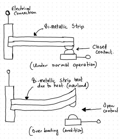
Inside the relay, the current passes through a heater element. This element is a small resistor that generates heat in proportion to the motor current. That heat acts on a bimetallic strip, which is made of two different metals bonded together. These two metals have different rates of thermal expansion. So when the bimetallic strip heats up, it bends because one metal expands faster than the other.
As the strip bends, it eventually reaches a point where it pushes against a trip mechanism. This mechanism opens the relay’s normally closed (NC) contact. The NC contact is connected in series with the contactor coil circuit. Opening this contact removes the supply to the contactor coil, which drops the contactor out and disconnects the motor.
Here is a simple practical example to make this clearer. Imagine a 15 kW, 415 V, three-phase induction motor with a full load current (FLC) of 30 A. If this motor gets overloaded due to a mechanical jam in the pump it is driving, the current might rise to 50 A or 60 A. This is well above the rated value. The heater elements in the thermal overload relay will start generating more heat than normal. The bimetallic strips will bend faster. After a period of time determined by the relay’s trip class and the magnitude of the overload, the relay will trip and disconnect the motor before the windings are damaged.
It is important to note that the thermal overload relay does not respond instantaneously. A small overload of 110% full load current might take several minutes to trip. A larger overload of 600% full load current, which often happens during a locked rotor condition, will trip much faster, usually within 10 to 30 seconds depending on the trip class.
4. Types of Thermal Overload Relays
There are two main types of thermal overload relays used in industrial motor protection. Each type has its own construction, advantages, and suitable applications.
4.1 Bimetallic Thermal Overload Relay
This is the most common and most widely used type. As explained in the working principle section, this relay uses bimetallic strips that bend when heated. The current passes through heater elements that heat these strips.
Bimetallic relays are simple, robust, and inexpensive. They do not require an external power supply to operate. They are suitable for most standard motor applications.
One limitation of bimetallic relays is that they are affected by the ambient temperature of the installation environment. A relay calibrated at 20°C will behave differently if installed in a control panel where the ambient temperature is 50°C. Most modern bimetallic relays include an ambient temperature compensation mechanism. This mechanism uses an additional bimetallic strip that compensates for the temperature difference so the relay trips at the correct current regardless of ambient conditions.
Bimetallic relays are available for current ranges from a fraction of an ampere to several hundred amperes. For larger currents, they are used with current transformers (CTs).
4.2 Electronic (Solid-State) Thermal Overload Relay
Electronic overload relays use current transformers or Hall-effect sensors to measure the actual motor current. A microprocessor then processes these current measurements and applies a thermal model to simulate the heat buildup inside the motor windings.
Because the electronic relay does not depend on physical heat or bimetallic strips, it is not affected by ambient temperature changes. It gives much more accurate protection.
Electronic overload relays also offer features that bimetallic relays cannot provide. These include phase loss protection, phase imbalance detection, ground fault detection, remote communication via Modbus or Profibus, adjustable trip class, and event logging.
Electronic relays are more expensive than bimetallic types. They also require a control power supply to operate the electronics.
5. Trip Classes of Thermal Overload Relays
One of the most important specifications of a thermal overload relay is its trip class. The trip class defines how quickly the relay will trip under a locked rotor condition, which is the worst-case overload scenario.
The trip class is defined in IEC 60947-4-1 (Low-Voltage Switchgear and Controlgear – Electromechanical Contactors and Motor Starters) and in NEMA ICS 2 (Industrial Control Devices, Controllers and Assemblies).
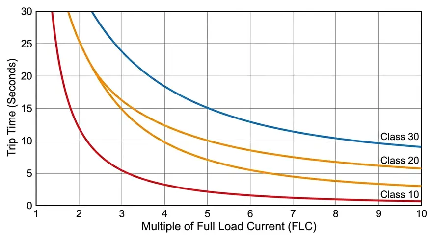
The standard trip classes are:
Class 10A – Trips in less than 2 seconds at 7.2 times full load current (FLC). Used for motors with very short starting times such as small pump motors or conveyor motors.
Class 10 – Trips within 4 to 10 seconds at 7.2 times FLC. This is the most common class and is suitable for most standard industrial motors including pumps, fans, and compressors.
Class 20 – Trips within 6 to 20 seconds at 7.2 times FLC. Suitable for motors that take longer to start, such as motors driving high-inertia loads like large fans or centrifuges.
Class 30 – Trips within 9 to 30 seconds at 7.2 times FLC. Used for motors with very long starting times, such as motors driving heavy crushers or mixers in mining or cement industries.
6. Thermal Overload Relay Wiring
A thermal overload relay is always wired in combination with a contactor. Together, they form what is called a motor starter. Here is how the wiring is organized.
6.1 Main Circuit (Power Circuit)
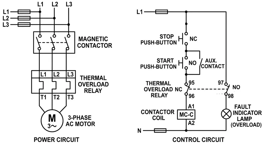
The three-phase supply is connected to the input terminals of the contactor (L1, L2, L3). The output terminals of the contactor (T1, T2, T3) are connected to the input terminals of the thermal overload relay (1/L1, 3/L2, 5/L3). The output terminals of the thermal overload relay (2/T1, 4/T2, 6/T3) are connected to the motor terminals (U, V, W).
6.2 Control Circuit
The relay has a normally closed (NC) auxiliary contact (usually labeled 95 and 96) and a normally open (NO) auxiliary contact (usually labeled 97 and 98). The NC contact (95-96) is connected in series with the contactor coil circuit. This means that when the relay trips, the NC contact opens, de-energizes the contactor coil, and the contactor drops out, disconnecting the motor from the supply.
The NO contact (97-98) can be used to signal an alarm or light up an indicator lamp to inform the operator that the relay has tripped.
The start and stop push buttons are also part of the control circuit. The stop button is connected in series with the NC contact of the relay, and the start button is connected with a holding contact across it for latching.
This wiring arrangement is the standard Direct-On-Line (DOL) starter circuit used across all industries worldwide.
7. Thermal Overload Relay Current Setting
Setting the thermal overload relay correctly is one of the most important tasks in motor protection. Setting it too low causes nuisance tripping. Setting it too high leaves the motor unprotected.
The standard rule, as outlined in NEC Article 430.32, is to set the overload relay at or below 125% of the motor’s full load current (FLC) for motors with a service factor of 1.15 or higher. For motors with a service factor of 1.0, the setting should be at or below 115% of FLC.
Here is a practical example. A three-phase induction motor has the following nameplate data:
- Voltage: 415 V
- Full Load Current (FLC): 28 A
- Service Factor: 1.15
Maximum overload relay setting = 28 A × 1.25 = 35 A
So you would set the relay’s current adjustment dial to 35 A or just below that value.
8. Reset Mechanism
After a thermal overload relay trips, the motor circuit is interrupted. Before the motor can be restarted, the relay must be reset. There are two types of reset mechanisms.
8.1 Manual Reset
The operator must physically press the reset button on the relay to reset it. The relay will only allow the reset button to work after it has cooled down sufficiently. This prevents the motor from being restarted immediately after a trip, which could damage the motor if the root cause of the overload has not been addressed.
Manual reset is the preferred mode in most industrial applications because it forces operators to investigate the trip cause before restarting.
8.2 Automatic Reset
The relay resets itself automatically after it cools down. The motor restarts on its own without any operator intervention. This mode is used in remote or unmanned installations where manual access is difficult, such as in pipeline pumping stations or offshore platforms. The risk with automatic reset is that if the root cause is not fixed, the motor might keep tripping and restarting, which accelerates wear.
Most modern thermal overload relays have a selector switch that allows the engineer to choose between manual and automatic reset modes.
9. Thermal Overload Relay vs. Motor Circuit Protector (MCP)
It is a common question in motor protection engineering whether a motor circuit protector (MCP) or a standard circuit breaker can replace a thermal overload relay. The answer is no, they cannot replace each other because they protect against different things.
A circuit breaker or motor circuit protector protects the circuit wiring against short circuits and ground faults. These are high-magnitude fault currents that must be cleared very quickly before the wiring is damaged. A circuit breaker trips in milliseconds to cycles for these faults.
A thermal overload relay protects the motor itself against sustained overload currents. These overloads might be 110% to 600% of FLC. They must be tolerated for short durations during motor starting, but if they persist, the relay trips to protect the motor windings.
The combination of a circuit breaker (or fuses) and a thermal overload relay gives the motor full protection. The circuit breaker handles short circuits and the relay handles overloads. Both devices are required in a properly designed motor protection system. This is what NEC Article 430 refers to as the “combination motor controller.”
10. Testing a Thermal Overload Relay
Testing a thermal overload relay on a regular basis is important for plant reliability and safety. A relay that has been in service for years without testing might not trip when expected.
10.1 Primary Injection Testing
This is the most accurate method. Test current is injected into the relay’s heater elements at a set multiple of the relay’s current setting (for example, at 7.2 times the setting for a locked rotor test). The trip time is measured and compared to the relay’s specified trip class curve. If the trip time falls within the class tolerance, the relay passes.
10.2 Secondary Injection Testing
For electronic overload relays, secondary injection tests can be performed by injecting signals into the relay’s current measurement inputs to simulate overcurrent conditions. The relay’s trip response is verified against its specifications.
10.3 Functional Test
A basic functional test involves manually pressing the test button (if available) to verify that the relay trips the contactor and that the control circuit responds correctly. This test confirms the wiring is correct but does not verify the relay’s current-time calibration.
11. Common Causes of Thermal Overload Relay Tripping
A thermal overload relay trips for a reason. When a trip occurs, the root cause must be identified before resetting the relay and restarting the motor. Here are the most common causes.
Motor Overload: The driven load has become too heavy for the motor. This could be caused by a mechanical jam, worn bearings, excessive product buildup in a pump or mixer, or incorrect loading.
Single Phasing / Phase Loss: As discussed, loss of one supply phase causes high current in the remaining phases, which trips the relay.
Incorrect Relay Setting: If the relay is set below the motor’s FLC or below 1.0 times FLC, it will trip under normal operating conditions. Always verify the setting against the motor nameplate.
High Ambient Temperature: If the relay is a bimetallic type without proper temperature compensation and is installed in a very hot environment, it may trip at lower currents than expected.
Voltage Imbalance: If the three-phase supply voltages are not balanced, the motor draws unequal currents in the three phases. This causes additional heating in the motor and can lead to overload relay tripping.
Motor Starting Problems: A motor that takes too long to start due to low supply voltage or a high-inertia load will draw high current for a long time, which can trip a relay that is not matched to the motor’s starting class.
12. Practical Application Example: Conveyor Belt Motor Protection
Let’s walk through a complete thermal overload relay application example for a conveyor belt motor in a manufacturing facility.
Motor Specifications:
- Power: 22 kW
- Voltage: 415 V, three-phase
- Full Load Current (FLC): 44 A
- Service Factor: 1.15
- Starting Method: DOL
Step 1 – Maximum Overload Relay Setting:
44 A × 1.25 = 55 A maximum setting
Step 2 – Trip Class Selection:
The conveyor motor starts under light load and accelerates in about 5 seconds. Class 10 relay allows up to 10 seconds, so Class 10 is suitable.
Step 3 – Relay Selection:
A bimetallic relay with current range 40 A – 57 A is selected. The dial is set to 55 A.
Step 4 – Contactor Compatibility:
A contactor rated for 22 kW at 415 V is used. The thermal overload relay is a direct-mount type compatible with this contactor model.
Step 5 – Reset Mode:
Manual reset is selected so that the maintenance team is alerted every time a trip occurs.
Protection Verification:
If the conveyor jams and the motor stalls (locked rotor condition), the current jumps to approximately 6 to 7 times FLC (264 to 308 A). At 7.2 × 55 A = 396 A, the Class 10 relay must trip within 4 to 10 seconds. The motor is protected before its windings can overheat significantly.
13. Conclusion
A thermal overload relay is a straightforward but highly effective device for protecting motors from overload damage. It sits between the contactor and the motor, continuously monitoring the current, and trips the circuit when the heat buildup inside the relay indicates that the motor is at risk.
Thermal overload relays have been in use for decades and remain the backbone of motor protection in industrial systems worldwide. A well-selected, properly set, and regularly tested thermal overload relay can extend motor life by years and prevent costly unplanned shutdowns.
14. Frequently Asked Questions (FAQs)
A thermal overload relay protects an electric motor from damage caused by overcurrent conditions. It detects when the motor is drawing more current than its rated value for too long and trips the contactor to disconnect the motor from the supply before the windings overheat and become damaged.
The ANSI device number for a machine thermal relay is Device 49, as defined in IEEE Standard C37.2. In motor protection schemes, it is often labeled 49M to specify that it protects a motor.
Class 10 relay trips within 4 to 10 seconds at 7.2 times the full load current. Class 20 relay trips within 6 to 20 seconds at the same test current. Class 20 is used for motors that take longer to start, such as motors driving high-inertia loads like large fans or centrifuges.
No. A circuit breaker protects the wiring against short circuits and ground faults. A thermal overload relay protects the motor against sustained overloads.
The relay current setting should be at or below 125% of the motor’s full load current (FLC) for motors with a service factor of 1.15 or higher, or at or below 115% of FLC for motors with a service factor of 1.0. This is specified in NEC Article 430.32.
A bimetallic relay uses a heated bimetallic strip to mechanically operate a trip mechanism. An electronic relay uses current sensors and a microprocessor to apply a thermal model.
Generally, a standard bimetallic thermal overload relay should not be placed between a VFD output and the motor. VFD output contains harmonics that can affect the relay’s accuracy. Most VFDs have a built-in electronic overload protection function.