
A stator earth fault is one of the most monitored faults in electrical machines, particularly in large synchronous generators. It happens when the insulation of the stator winding breaks down and allows a conducting path to form between the winding and the stator core (which is grounded). This is not a theoretical concern. It is a real-world problem that power plant engineers and protection engineers deal with regularly.
In a healthy machine, the stator winding is fully insulated from the stator core. The moment insulation fails at any point, fault current begins to flow from the winding conductor to the grounded stator core. Even a very small fault current, if left undetected, can burn through laminations, damage the stator core permanently, and result in a very expensive repair or machine replacement.
In this technical guide, we will discuss everything you need to know about stator earth fault protection, including its working principle, types, applications, relay settings, coordination strategies, testing methods, and relevant industry standards. Practical examples are included throughout to help you apply these concepts in real-world scenarios confidently.
1. What Is a Stator Earth Fault?
The stator is the stationary part of an electrical machine, such as a generator or motor. It contains the three-phase winding that carries alternating current. The stator winding is wound around a laminated iron core. This iron core is physically connected to the earth (ground) as part of the machine’s design and safety requirements.
A stator earth fault occurs when the electrical insulation of the stator winding breaks down at one or more points, creating a conducting path between the winding and the stator core. Since the core is grounded, this fault allows current to flow through an unintended path from the winding conductor directly to earth.
In a simple analogy, imagine a water pipe that carries pressurized water. The pipe is covered with rubber insulation to prevent leakage. If a hole develops in the rubber, water leaks to the surroundings. A stator earth fault works similarly — electricity leaks from the winding conductor to the surrounding iron core.
The severity of a stator earth fault depends on several factors:
- The location of the fault on the stator winding
- The grounding method used for the generator neutral
- The magnitude of the fault current
- How quickly the protection system responds
A fault occurring near the generator terminals is the most damaging because the full phase-to-earth voltage drives a large fault current. A fault occurring near the neutral end of the winding sees a lower driving voltage and produces a smaller fault current. However, even a low-current earth fault near the neutral end can grow into a more damaging fault if it is not cleared promptly.
2. Causes of Stator Earth Fault
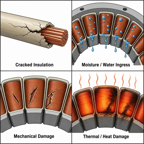
Stator earth faults do not happen suddenly without a reason. There are several known causes that electrical engineers must be aware of:
2.1 Insulation Aging
Stator winding insulation degrades over time. Heat, electrical stress, and mechanical vibration all contribute to insulation aging. As insulation becomes brittle and thin over years of operation, it can crack and eventually fail. This is the most common cause in older machines.
2.2 Moisture Ingress
Water or high humidity inside a machine reduces the insulation resistance of the stator winding. If moisture gets trapped in the winding slots, it lowers the dielectric strength of the insulation. Over time, this leads to partial discharge activity and eventually an earth fault.
2.3 Thermal Stress
Repeated heating and cooling cycles cause the winding insulation to expand and contract. Over time, this mechanical stress leads to micro-cracks in the insulation material. Areas with high thermal stress — such as the winding ends and slot exits — are more vulnerable.
2.4 Mechanical Damage
Foreign objects, vibration, or manufacturing defects can physically damage the insulation of the stator winding. In some cases, during rewinding or maintenance work, insulation damage can be accidentally introduced.
2.5 Overvoltage Conditions
Transient overvoltages caused by lightning strikes, switching surges, or fault conditions on the power system can stress and puncture the stator insulation. This is why surge protection is important alongside stator earth fault protection.
2.6 Contamination
Oil, dust, carbon particles, and other conducting contaminants can settle on the stator winding ends. These materials reduce surface insulation resistance and create a conducting path to the frame.
3. Effects of a Stator Earth Fault
Stator earth faults, if not cleared promptly, cause progressive damage that can go from a minor insulation failure to a major machine failure.
3.1 Stator Core Damage
The most serious effect of a stator earth fault is damage to the stator core laminations. Fault current flowing through the laminations generates intense heat at the fault point. This heat can fuse and weld the laminations together. Repairing damaged stator core laminations is an extremely expensive and time-consuming process. In some cases, the entire stator core needs replacement.
3.2 Second Earth Fault Risk
A single earth fault on a solidly grounded system produces immediate high fault current. On a high-impedance grounded system, a single earth fault may produce very little current. However, the danger is that if a second earth fault occurs on a different phase or a different location of the same winding, the result is a phase-to-phase or two-point earth fault. This type of fault produces high current and can severely damage the machine.
3.3 Winding Damage
Fault current at the fault point burns through the conductor insulation and the conductor itself. This can extend the damage along the winding, increasing the scope and cost of repair.
3.4 Extended Outage
A stator earth fault that is not detected early results in major damage, leading to extended machine outage. Rewinding a large generator stator can take weeks or months. This translates directly to lost generation revenue.
4. How Stator Earth Fault Protection Works
The goal of stator earth fault protection is to detect a conducting path between the stator winding and the grounded stator core, and then send a trip signal to isolate the machine before major damage occurs.
The protection system achieves this goal by monitoring either:
- The voltage developed across the neutral grounding impedance, or
- The current flowing through the neutral-to-earth connection, or
- The third harmonic voltage at the neutral and terminal ends of the stator winding
The choice of detection method depends on the grounding method used for the generator neutral.
5. Generator Neutral Grounding Methods
The grounding method used for the generator neutral has a direct impact on how stator earth fault protection is designed.
5.1 Solid (Direct) Grounding
The generator neutral is connected directly to earth. A stator earth fault produces a very high fault current. This method is not used for large generators because the high fault current causes severe stator core damage.
5.2 Low-Impedance Grounding
The generator neutral is connected to earth through a low-value resistor or reactor. Fault current is limited but still measurable. This method allows residual current protection to work effectively.
5.3 High-Impedance Grounding
The generator neutral is connected to earth through a high-resistance grounding resistor or a distribution transformer with a loading resistor on the secondary side. The fault current is limited to a very small value — typically less than 10 amperes, often less than 1 ampere in large generators. This prevents stator core damage even if the fault persists for a short time. High-impedance grounding is the standard practice for large synchronous generators.
6. 95% Stator Earth Fault Protection (ANSI 64G1 / ANSI 59N)
The most common stator earth fault protection scheme for large high-impedance grounded generators uses a neutral overvoltage relay (ANSI 59N) connected across the neutral grounding resistor or the secondary of the neutral grounding transformer.
6.1 How It Works
In normal (healthy) operation, the three-phase voltages in a balanced generator system produce zero (or near-zero) residual voltage at the neutral. The voltage across the neutral grounding resistor is essentially zero.
When a stator earth fault occurs, the voltage balance is disturbed. A voltage proportional to the distance of the fault from the neutral point appears across the neutral grounding resistor. The 59N relay detects this voltage rise and issues a trip signal.
6.2 Coverage Limitation
This scheme covers approximately 90% to 95% of the stator winding from the terminal end toward the neutral. The remaining 5% to 10% near the neutral end cannot be protected by this method. This is because a fault very close to the neutral point produces a very small voltage across the neutral grounding resistor — too small for the relay to detect reliably.
6.3 Relay Setting Example
For a generator with a neutral grounding transformer secondary voltage of 240 V at full rated voltage:
- The 59N relay pickup voltage is typically set at 5% to 10% of the rated neutral voltage.
- A pickup setting of 5% × 240 V = 12 V is a common starting point.
- Time delay is set to coordinate with other protection functions. A typical time delay is 0.5 to 1.0 second to ride through transient conditions.
This setting ensures the relay trips for faults at 90% to 95% of the winding from the neutral point while being stable during normal transients.
6.4 Practical Example
Consider a 100 MVA, 11 kV generator with high-impedance grounding through a neutral grounding transformer. The transformer secondary has a 240 V, 10-ohm loading resistor. A phase-to-earth fault occurs at 85% of the winding distance from the neutral. The voltage developed across the neutral grounding transformer secondary is calculated as follows:
Voltage at secondary = (Fault distance from neutral / Total winding) × Rated secondary voltage
= (0.85) × 240 V
= 204 V
The 59N relay pickup is set at 12 V. Since 204 V is much greater than 12 V, the relay will operate and trip the machine.
Now consider a fault at 3% from the neutral:
= 0.03 × 240 V = 7.2 V
Since 7.2 V is less than the relay pickup of 12 V, the relay does not operate. This is the unprotected zone — the 5% near the neutral end.
7. 100% Stator Earth Fault Protection (ANSI 64G2 — Third Harmonic Method)
To protect the remaining 5% of the stator winding near the neutral end, a second protection scheme is added. This is the 100% stator earth fault protection, using the third harmonic voltage method.
Large synchronous generators naturally produce a small amount of third harmonic voltage (150 Hz in a 50 Hz system, or 180 Hz in a 60 Hz system) due to the shape of the magnetic flux waveform in the machine. This third harmonic voltage appears across the entire stator winding. In a healthy generator, a measurable third harmonic voltage exists at both the neutral end and the terminal end of the stator winding.
The third harmonic voltage distribution is roughly opposite at the two ends. When the neutral end has higher third harmonic voltage, the terminal end has lower third harmonic voltage, and vice versa. This natural distribution is used as a reference.
7.1 How the Third Harmonic Method Works
When an earth fault occurs near the neutral end of the stator winding (the zone that 59N cannot protect), the third harmonic voltage at the neutral end collapses toward zero. The relay (64G2) monitors the third harmonic voltage at the neutral. A reduction in this voltage below the normal healthy value indicates a fault near the neutral end. The relay then sends a trip signal.
Some modern protection relays use a ratio method (comparing third harmonic voltage at the neutral to that at the terminals) to make the detection more reliable across different operating conditions and load levels.
7.2 Limitation of the Third Harmonic Method
Not all generators produce enough third harmonic voltage for this method to work. Generators with certain winding configurations may produce very little third harmonic voltage. The relay manufacturer and the generator manufacturer must confirm that sufficient third harmonic voltage is present before this scheme is applied.
7.3 Practical Example
A 250 MVA generator produces 3% third harmonic voltage under normal load. The 64G2 relay is set to operate if the third harmonic voltage at the neutral drops below 50% of the normal value. A winding fault at 2% from the neutral causes the third harmonic voltage to drop from 3% to 0.8% of rated voltage. Since this is well below 50% of normal, the relay operates and trips the machine protecting the zone that the 59N relay could not reach.
8. Alternative 100% Stator Earth Fault Protection — Subharmonic (Low-Frequency) Injection Method
An alternative method for achieving 100% stator earth fault protection is the low-frequency voltage injection method. In this scheme, a low-frequency voltage signal (12.5 Hz or 20 Hz) is injected into the neutral-to-earth connection of the generator through the neutral grounding transformer.
8.1 How It Works
The injection source feeds a low-frequency test signal continuously into the stator winding insulation system. A measuring relay monitors the resulting current flow. In a healthy generator, the insulation resistance is very high, so only a tiny test current flows.
When insulation breaks down at any point on the stator winding including at the neutral end the fault path provides a low-resistance route for the injected current. The relay detects the increase in injected current and operates.
8.2 Advantages of This Method
This method can detect earth faults anywhere on the stator winding, from terminal to neutral, achieving true 100% coverage. It can also work while the machine is at standstill — unlike the third harmonic method, which requires the generator to be running and loaded.
This method is increasingly used in modern protection systems and is supported by relays from major manufacturers such as GE, Siemens, ABB, and SEL.
9. Residual Current Method for Stator Earth Fault Detection
For smaller generators or motors, a simpler method called the residual current method is used. This involves connecting three current transformers (CTs) — one on each phase — in a residual connection (sometimes called a Holmgreen connection). The outputs of the three CTs are summed together.
In a healthy balanced system, the vector sum of the three-phase currents is zero. No current flows through the residual path. When an earth fault occurs, the current balance is disturbed. A residual current flows, and the relay detects this and operates.
A simpler variation uses a single core-balance CT (also called a zero-sequence CT or a ring CT). All three-phase conductors pass through the core of this CT together. Under healthy conditions, the flux from the three phases cancels, and the CT output is zero. An earth fault produces a net residual flux, and the CT produces an output that the relay detects.
10. Stator Earth Fault Protection in Motors
Stator earth fault protection is also applied to motors, especially large HV (high-voltage) motors used in industrial applications. The approach is similar to generator protection, but with some differences:
- Motors are usually connected to a grounded power supply, so the fault current is higher.
- Core-balance CTs are commonly used for motor stator earth fault protection.
- The relay function is ANSI 64 or 51N.
- Trip time is set to be fast often less than 100 milliseconds because motor stator damage from earth fault current can be rapid.
11. Testing Stator Earth Fault Protection
Testing stator earth fault protection is done at two levels: testing the insulation of the stator winding itself, and testing the relay and protection circuit.
11.1 Insulation Resistance (IR) Testing
An insulation resistance test using a megohmmeter (megger) is performed on the stator winding before and after maintenance. The winding is disconnected from the circuit, and a DC voltage (typically 1 kV, 2.5 kV, or 5 kV depending on the machine rating) is applied between the winding conductor and the earth.
A healthy stator winding shows insulation resistance values in the hundreds of megohms or even gigohms range. Readings below 1 MΩ (or below the minimum acceptable value calculated using the polarization index method) indicate insulation deterioration.
11.2 Polarization Index (PI) Test
The polarization index is the ratio of the 10-minute IR reading to the 1-minute IR reading. A PI value above 2.0 is generally acceptable. A PI value below 1.5 suggests that the insulation condition is poor and further investigation is needed.
11.3 High Potential (Hi-Pot) Testing
A high-potential (DC or AC) test applies a voltage higher than the normal operating voltage across the insulation to check its dielectric strength. This test is done during commissioning and major overhauls. It must be carried out carefully as it can damage already-weakened insulation.
11.4 Relay Injection Testing
The stator earth fault relay itself must be tested using a secondary injection test. A test set injects a controlled voltage into the relay’s voltage input (for 59N relay testing). The engineer verifies that the relay operates at the set pickup voltage and within the expected time delay.
11.5 Primary Injection Testing
In some cases, primary injection testing is performed to verify the complete protection circuit, including the neutral grounding transformer, measuring relay, wiring, and trip circuit. This is done during commissioning of new generators.
12. Conclusion
Stator earth fault protection is one of the most important aspects of electrical machine protection. A fault in the stator winding, if left undetected, can damage the stator core in a way that takes months to repair and costs a great deal of money. Protection engineers use a combination of methods including neutral overvoltage relays (ANSI 59N), ground protection relays (ANSI 64G1 and 64G2), and low-frequency injection schemes to cover the full length of the stator winding.
The choice of protection scheme depends on the generator rating, the neutral grounding method, and the available third harmonic voltage. Regular testing of both the insulation system and the protection relays is necessary to keep the protection in reliable working condition.
13. Frequently Asked Questions (FAQs)
A stator earth fault occurs when the stator winding conductor makes contact with the grounded stator core, creating a path to earth. A stator phase fault (also called a phase-to-phase fault) occurs when two different phase windings make contact with each other.
High-impedance grounding limits the fault current to a very small value — often just a few amperes. This means that even if a stator earth fault occurs and takes a few seconds to be detected and cleared, the stator core damage is minimal.
The primary ANSI code for stator earth fault protection in generators is ANSI 64G (Generator Ground Protection). More specifically, ANSI 64G1 refers to the 95% stator earth fault protection using neutral overvoltage (59N relay), and ANSI 64G2 refers to the 100% protection using the third harmonic method. ANSI 59N (Neutral Overvoltage Relay) is the relay function most commonly used for the 64G1 scheme.
The third harmonic method (64G2) requires the generator to be running and producing power to work. However, the subharmonic (low-frequency) injection method can detect stator earth faults even when the machine is at standstill.
If a stator earth fault is not cleared quickly, the fault current burns through the stator core laminations at the fault point. The heat fuses the laminations together and oxidizes the iron. This is called stator core burning.